|
SA Initial Attach Sequence In Detail
Following is high level sequence of call processing with SA(Stand Alone) initial attach process. For the simplicity, I have listed the sequence that is exchanged between UE and NW(Network) over the air (OTA). In reality, there are a lot of other signalings happending in corenetwork during the attach process.
- SA Initial Attach - Overall Signaling Flow
- SA Initial Attach - Sequence in Detail
- Get the Test Procedure and Log / Amarisoft TechAcademy
SA Initial Attach - Overall Signaling Flow
A simplified call processing (Signaling Flow) of SA Initial Attach process with focus on OTA (Over The Air) message is illustrated as below. If you want to get more detailed flow including the signaling flow in core network as well, For corenetwork side signaling, refer to ref [2] from event Helix which is very nicely written sequence diagram. In the diagram below, I packed multiple steps (multiple signaling message) into one process for the simplicity. We will get the each and every detailed steps in next section.
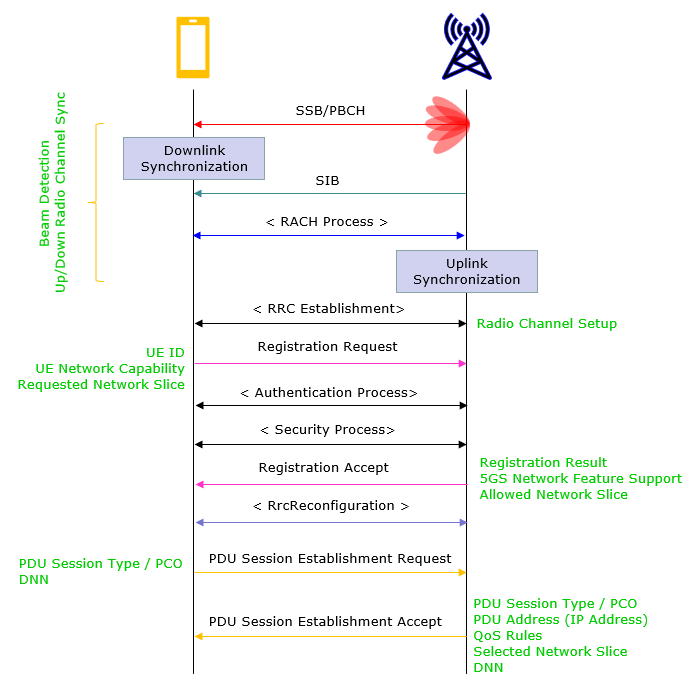
Downlink / Uplink Synchronization:
The first step in 5G Standalone (SA) call processing is to synchronize the UE (User Equipment) with the gNB (gNodeB). We can split this into two parts : Downlink synchronization and Uplink synchronization. Downlink sync comes first and then Uplink sync happens.
Downlink Synchronization : the UE performs cell search and acquiring the synchronization signals, Primary Synchronization Signal (PSS) and Secondary Synchronization Signal (SSS), which help the UE to identify the cell and synchronize with its timing.
Uplink Synchronization : This is achieved by RACH Process. The Random Access Channel (RACH) is used by the UE for initial uplink synchronization with the gNB. It involves transmitting a randomly chosen preamble from the UE, which the gNB detects and responds with a timing adjustment. This process enables the UE to align its transmission timing with the gNB, allowing for efficient communication.
RRC Establishment:
After synchronization, the UE initiates the Radio Resource Control (RRC) connection establishment procedure by sending an RRCSetupRequest message to the gNB. The gNB responds with an RRCSetup message, which includes essential configuration information for the UE to access network resources.
Registration Request:
Once the RRC connection is established, the UE sends a Registration Request message to the network (Core Network, specifically the Access and Mobility Management Function, AMF) to register with the 5G network. This message includes important information such as the UE's security credentials and UE's network capability.
Authentication Process:
To ensure secure communication, the network initiates an authentication process. The AMF generates an authentication challenge for the UE, which includes a random number and an expected authentication response. The UE computes the authentication response based on the challenge and its security credentials, and sends it back to the AMF. If the response matches the expected value, the authentication is successful.
Security Process:
After successful authentication, the UE and network establish security keys for secure communication. The AMF sends a Security Mode Command to the UE, specifying the security algorithms to be used for ciphering and integrity protection. The UE acknowledges the command with a Security Mode Complete message.
Registration Accept:
Once the security process is complete, the AMF sends a Registration Accept message to the UE, which includes the UE's 5G-GUTI (Globally Unique Temporary Identifier) and other relevant configuration information. The UE is now successfully registered with the 5G network.
RrcReconfiguration:
After successful registration, the gNB sends an RRCReconfiguration message to the UE, which includes the configuration information necessary for data transmission, such as the Radio Bearer and Physical Layer configurations.
PDU Session Establishment Request:
To establish a data session, the UE sends a PDU (Protocol Data Unit) Session Establishment Request message to the network (specifically, the Session Management Function, SMF). This message includes the UE's data session requirements, SSC Mode, PCO, DNN etc.
PDU Session Establishment Accept:
The SMF processes the PDU Session Establishment Request and allocates the necessary resources for the data session. The SMF sends a PDU Session Establishment Accept message to the UE, which contains the PDU session configuration information, such as the allocated QoS and the IP address. The UE is now ready for data transmission over the established PDU session.
SA Initial Attach - Sequence in Detail
The detailed mechanism for each of these step is very complicated process which cannot be described in the single page. Try follow through the hyperlink at each step if you want further details. Notice that there are multiple linkes even at single step. I am just trying to provide just high level / skeleton in this page.
|
Step |
Direction |
Message |
Comment |
|
1 |
UE <- NW |
SSB (PSS,SSS,MIB) | |
|
2 |
UE <- NW |
PDCCH / CORESET 0 / DCI 1_0 | |
|
3 |
UE <- NW |
SIB1 | |
|
4 |
UE <- NW |
PDCCH / DCI 1_0 | |
|
5 |
UE <- NW |
Other SIBs | |
|
6 |
UE -> NW |
Msg1 (PRACH/Preamble) | |
|
7 |
UE <- NW |
||
|
8 |
UE <- NW |
Msg2 (PDSCH / Random Access Response) | |
|
9 |
UE -> NW |
Msg3 (RRC Setup Request) | |
|
10 |
UE <- NW |
||
|
11 |
UE <- NW |
Msg4 (PDSCH / CR+RRC Setup) | |
|
12 |
UE <- NW |
(PDCCH / DCI 0_0 or 0_1, C_RNTI) |
|
|
13 |
UE -> NW |
||
|
14 |
UE -> NW |
(PUSCH) RRCSetupComplete+NAS:RegistrationRequest | |
|
15 |
UE <- NW |
(PDCCH/ DCI 1_0 or 1_1, C_RNTI) |
|
|
16 |
UE <- NW |
(PDSCH) NAS:IdentityRequest |
|
|
17 |
UE -> NW |
||
|
18 |
UE <- NW |
(PDCCH/ DCI 0_0 or 0_1, C_RNTI) |
|
|
19 |
UE -> NW |
(PUSCH) NAS:IdentityResponse |
|
|
20 |
UE <- NW |
(PDCCH/ DCI 1_0 or 1_1, C_RNTI) |
|
|
21 |
UE <- NW |
(PDSCH) NAS:AuthenticationRequest |
|
|
22 |
UE -> NW |
||
|
23 |
UE <- NW |
(PDCCH/ DCI 0_0 or 0_1, C_RNTI) |
|
|
24 |
UE -> NW |
(PUSCH) NAS:AuthenticationResponse |
|
|
25 |
UE <- NW |
(PDCCH/ DCI 1_0 or 1_1, C_RNTI) |
|
|
26 |
UE <- NW |
(PDSCH) NAS:SecurityModeCommand |
|
|
27 |
UE -> NW |
||
|
28 |
UE <- NW |
(PDCCH/ DCI 0_0 or 0_1, C_RNTI) |
|
|
29 |
UE -> NW |
(PUSCH) NAS:SecurityModeCommandComplete |
|
|
30 |
UE <- NW |
(PDCCH/ DCI 1_0 or 1_1, C_RNTI) |
|
|
31 |
UE <- NW |
(PDSCH) RRC:SecurityModeCommand |
|
|
32 |
UE -> NW |
||
|
33 |
UE <- NW |
(PDCCH/ DCI 0_0 or 0_1, C_RNTI) |
|
|
34 |
UE -> NW |
(PUSCH) RRC:SecurityModeCommandComplete |
|
|
35 |
UE <- NW |
(PDCCH/ DCI 1_0 or 1_1, C_RNTI) |
|
|
36 |
UE <- NW |
||
|
37 |
UE -> NW |
||
|
38 |
UE <- NW |
(PDCCH/ DCI 0_0 or 0_1, C_RNTI) |
|
|
39 |
UE -> NW |
(PUSCH) RRCReconfigurationComplete + NAS : Registration Complete |
|
|
40 |
UE <- NW |
(PDCCH/ DCI 0_0 or 0_1, C_RNTI) |
|
|
41 |
UE -> NW |
(PUSCH) ULInformationTransfer + UL NAS Transport |
|
|
42 |
UE <- NW |
(PDCCH/ DCI 0_0 or 0_1, C_RNTI) |
|
|
43 |
UE <- NW |
(PDSCH) DLInformationTransfer + DL NAS Transport |
|
|
44 |
UE -> NW |
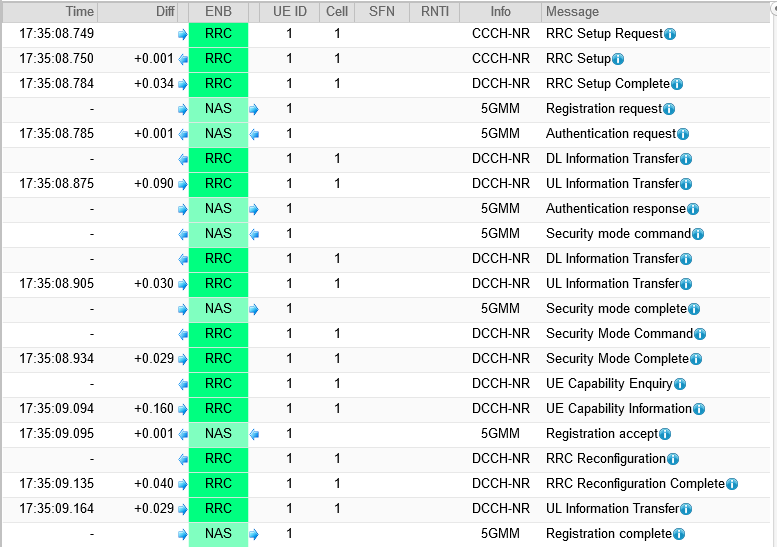
Example 01 > NR SA Initial Registration Sequence - Amarisoft
Following is a sample protocol sequence for NR SA Registration kindly provided by Amarisoft in its web based log viewer
For the example of the contents of these messages click on the message link shown in the above table.
Followings are contents of the signaling message for the SA initial sequence. Some of the message are not listed here because it would not be considered mandatory.
- [RRC Setup Request]
- [RRC Setup]
- [Registration Request]
- [Authentication Request]
- [Authentication Response]
- [Security Mode Command - NAS]
- [Security Mode Complete - NAS]
- [Security Mode Command - RRC]
- [Security Mode Complete - RRC]
- [Registration Accept]
- [Registration Complete]
- [RrcReconfiguration]
- [PDU Session Establishment Request]
- [PDU Session Establishment Accept]
This is the first RRC message from UE requesting RrcSetup. It includes a unique binary identifier for the user equipment (UE) under ue-Identity, specifies mobile-originated signaling as the establishment cause under establishmentCause
{
message c1: rrcSetupRequest: {
rrcSetupRequest {
ue-Identity randomValue: '110110011101110100011000000110100000011'B,
establishmentCause mo-Signalling,
spare '0'B
}
}
}
This is Rrc Setup message in response to RRC Request. This setup message is structured to provide detailed configurations necessary for the communication between the User Equipment (UE) and the network, covering various aspects like radio bearer setup, cell group configurations, and special cell configurations for both uplink and downlink communication channels.
Overall structure / contents in this example can be summarized as below : (I think it would be a good practice to convert the RRC message into this kind of summary format for you to get familiar with the meaning and structure of this super complicated message)
- Radio Bearer Configuration:
- Setup of Signalling Radio Bearer (SRB) with identity 1.
- Master Cell Group Configuration:
- Cell Group ID is set to 0 with various configurations for RLC (Radio Link Control), MAC (Medium Access Control), and Physical Cell group.
- Uplink and Downlink configurations for Acknowledgement/Retransmission, Resource allocation, and scheduling requests.
- Special Cell Configuration (spCellConfig):
- Dedicated configurations for initial Downlink and Uplink Bandwidth Part (BWP) which include:
- Control Resource Set and Search Space configurations for downlink. // Check out this note for the details of CORESET
- One control resource set defined with ID 2
- Frequency domain resources set to the 48RBs from RB0
- Duration of 1 slot
- Non-interleaved CCE-to-REG mapping
- Precoder granularity same as REG bundle
- One UE specific search space defined with ID 2
- Monitoring periodicity is one slot
- Monitoring symbols in slot set to first 6 symbols
- Number of PDCCH candidates defined per aggregation level
- Search space monitors DCI formats 0-1 and 1-1
- PUCCH configurations for uplink control signal resource setup // Check out this note for the details of PUCCH Configuration
- Two PUCCH resource sets defined - set 0 with resources 0-7, set 1 with resources 8-11
- 12 PUCCH format 1 resources defined with different starting PRBs, cyclic shifts and OCCs
- 4 PUCCH format 2 resources defined with different starting symbols
- Format 1 setup has no additional parameters
- Format 2 setup specifies max code rate of 0.25
- One scheduling request resource defined with ID 1, periodicity/offset of sl40:8, using resource 12
- dl-DataToUL-ACK maps DL slots 8,7,6,5,4,12,11 to UL ACK slots
- PUSCH configurations for uplink data channel, specifying resource sets and modulation schemes. // Check out this note for the details of PUSCH Configuration
- Transmission mode is codebook based.
- DMRS mapping type A, with additional DMRS position at pos1.
- No transform precoding.
- Power control settings
- msg3 alpha of alpha1.
- Nominal PUSCH power of -84 dBm without grant.
- One PUSCH alpha set defined with ID 0.
- Pathloss reference RS is SSB index 0.
- One PUSCH power control ID 0 defined mapped to pathloss RS 0 and alpha set 0.
- Resource allocation is type 1 (dynamic).
- Non-coherent codebook subset.
- Max rank is 1.
- UCI on PUSCH uses beta offsets of 9 for ACK, 7 for CSI part 1 and 2.
- UCI scaling is set to f1.
- SRS Configuration
- One SRS resource set defined with ID 0 containing SRS resource 0.
- Resource type is aperiodic with trigger value 1 and slot offset 7.
- Usage is codebook based.
- Reference power is -84 dBm with pathloss reference as SSB 0.
- One SRS resource defined with ID 0.
- Port configuration is 1 antenna port.
- Comb pattern is n2 with comb offset 0 and cyclic shift 0.
- Mapping uses start position 0, n1 symbols, repetition factor 1.
- Frequency position is 0 and shift is 5.
- Frequency hopping enabled using c-SRS 11 and b-SRS 3, no b-hop.
- Neither group nor sequence hopping.
- Resource type aperiodic.
- Sequence ID 500.
- CSI (Channel State Information) Measurement configurations specifying resources and reporting configurations. // Check out this note for the details of CSI framework
- 5 NZP CSI-RS resources defined with different ports, CDM types, densities and periodicities. one of them is for CSI report and the other four are for TRS.
- 2 NZP CSI-RS sets - set 0 contains resource 0 (for csi report), set 1 contains resources 1-4 enables TRS (for TRS)
- 1 CSI-IM resource defined with pattern 1 and periodicity
- 1 CSI-IM set containing CSI-IM resource 0
- 3 CSI resource configs defined - one using NZP set 0, one using CSI-IM set 0, one using NZP set 1
- 1 CSI report config:
- Uses resource 0 for channel and resource 1 for interference
- Periodic reporting on PUCCH every 80 slots
- Reports CRI, RI, PMI, CQI
- Wideband CQI and PMI
- Codebook type 1 single panel with 2 ports
- CQI table 2, subband size 1 RBG
Followings are the entire contents of the message.
{
message c1: rrcSetup: {
rrc-TransactionIdentifier 0,
criticalExtensions rrcSetup: {
radioBearerConfig {
srb-ToAddModList {
{
srb-Identity 1
}
}
},
masterCellGroup {
cellGroupId 0,
rlc-BearerToAddModList {
{
logicalChannelIdentity 1,
servedRadioBearer srb-Identity: 1,
rlc-Config am: {
ul-AM-RLC {
sn-FieldLength size12,
t-PollRetransmit ms45,
pollPDU infinity,
pollByte infinity,
maxRetxThreshold t8
},
dl-AM-RLC {
sn-FieldLength size12,
t-Reassembly ms35,
t-StatusProhibit ms0
}
},
mac-LogicalChannelConfig {
ul-SpecificParameters {
priority 1,
prioritisedBitRate infinity,
bucketSizeDuration ms5,
logicalChannelGroup 0,
schedulingRequestID 0,
logicalChannelSR-Mask FALSE,
logicalChannelSR-DelayTimerApplied FALSE
}
}
}
},
mac-CellGroupConfig {
schedulingRequestConfig {
schedulingRequestToAddModList {
{
schedulingRequestId 0,
sr-TransMax n64
}
}
},
bsr-Config {
periodicBSR-Timer sf20,
retxBSR-Timer sf320
},
tag-Config {
tag-ToAddModList {
{
tag-Id 0,
timeAlignmentTimer infinity
}
}
},
phr-Config setup: {
phr-PeriodicTimer sf500,
phr-ProhibitTimer sf200,
phr-Tx-PowerFactorChange dB3,
multiplePHR FALSE,
dummy FALSE,
phr-Type2OtherCell FALSE,
phr-ModeOtherCG real
},
skipUplinkTxDynamic FALSE
},
physicalCellGroupConfig {
pdsch-HARQ-ACK-Codebook dynamic
},
spCellConfig {
spCellConfigDedicated {
initialDownlinkBWP {
pdcch-Config setup: {
controlResourceSetToAddModList {
{
controlResourceSetId 2,
frequencyDomainResources '111111110000000000000000000000000000000000000'B,
duration 1,
cce-REG-MappingType nonInterleaved: NULL,
precoderGranularity sameAsREG-bundle
}
},
searchSpacesToAddModList {
{
searchSpaceId 2,
controlResourceSetId 2,
monitoringSlotPeriodicityAndOffset sl1: NULL,
monitoringSymbolsWithinSlot '10000000000000'B,
nrofCandidates {
aggregationLevel1 n0,
aggregationLevel2 n2,
aggregationLevel4 n1,
aggregationLevel8 n0,
aggregationLevel16 n0
},
searchSpaceType ue-Specific: {
dci-Formats formats0-1-And-1-1
}
}
}
},
pdsch-Config setup: {
dmrs-DownlinkForPDSCH-MappingTypeA setup: {
dmrs-AdditionalPosition pos1
},
tci-StatesToAddModList {
{
tci-StateId 0,
qcl-Type1 {
referenceSignal ssb: 0,
qcl-Type typeD
}
}
},
resourceAllocation resourceAllocationType1,
rbg-Size config1,
prb-BundlingType staticBundling: {
bundleSize wideband
},
zp-CSI-RS-ResourceToAddModList {
{
zp-CSI-RS-ResourceId 0,
resourceMapping {
frequencyDomainAllocation row4: '100'B,
nrofPorts p4,
firstOFDMSymbolInTimeDomain 8,
cdm-Type fd-CDM2,
density one: NULL,
freqBand {
startingRB 0,
nrofRBs 52
}
},
periodicityAndOffset slots80: 1
}
},
p-ZP-CSI-RS-ResourceSet setup: {
zp-CSI-RS-ResourceSetId 0,
zp-CSI-RS-ResourceIdList {
0
}
}
}
},
firstActiveDownlinkBWP-Id 0,
uplinkConfig {
initialUplinkBWP {
pucch-Config setup: {
resourceSetToAddModList {
{
pucch-ResourceSetId 0,
resourceList {
0,
1,
2,
3,
4,
5,
6,
7
}
},
{
pucch-ResourceSetId 1,
resourceList {
8,
9,
10,
11
}
}
},
resourceToAddModList {
{
pucch-ResourceId 0,
startingPRB 50,
intraSlotFrequencyHopping enabled,
secondHopPRB 0,
format format1: {
initialCyclicShift 0,
nrofSymbols 14,
startingSymbolIndex 0,
timeDomainOCC 0
}
},
{
pucch-ResourceId 1,
startingPRB 50,
intraSlotFrequencyHopping enabled,
secondHopPRB 0,
format format1: {
initialCyclicShift 4,
nrofSymbols 14,
startingSymbolIndex 0,
timeDomainOCC 0
}
},
{
pucch-ResourceId 2,
startingPRB 50,
intraSlotFrequencyHopping enabled,
secondHopPRB 0,
format format1: {
initialCyclicShift 8,
nrofSymbols 14,
startingSymbolIndex 0,
timeDomainOCC 0
}
},
{
pucch-ResourceId 3,
startingPRB 50,
intraSlotFrequencyHopping enabled,
secondHopPRB 0,
format format1: {
initialCyclicShift 0,
nrofSymbols 14,
startingSymbolIndex 0,
timeDomainOCC 1
}
},
{
pucch-ResourceId 4,
startingPRB 50,
intraSlotFrequencyHopping enabled,
secondHopPRB 0,
format format1: {
initialCyclicShift 4,
nrofSymbols 14,
startingSymbolIndex 0,
timeDomainOCC 1
}
},
{
pucch-ResourceId 5,
startingPRB 50,
intraSlotFrequencyHopping enabled,
secondHopPRB 0,
format format1: {
initialCyclicShift 8,
nrofSymbols 14,
startingSymbolIndex 0,
timeDomainOCC 1
}
},
{
pucch-ResourceId 6,
startingPRB 50,
intraSlotFrequencyHopping enabled,
secondHopPRB 0,
format format1: {
initialCyclicShift 0,
nrofSymbols 14,
startingSymbolIndex 0,
timeDomainOCC 2
}
},
{
pucch-ResourceId 7,
startingPRB 50,
intraSlotFrequencyHopping enabled,
secondHopPRB 0,
format format1: {
initialCyclicShift 4,
nrofSymbols 14,
startingSymbolIndex 0,
timeDomainOCC 2
}
},
{
pucch-ResourceId 8,
startingPRB 1,
intraSlotFrequencyHopping enabled,
secondHopPRB 49,
format format2: {
nrofPRBs 1,
nrofSymbols 2,
startingSymbolIndex 0
}
},
{
pucch-ResourceId 9,
startingPRB 1,
intraSlotFrequencyHopping enabled,
secondHopPRB 49,
format format2: {
nrofPRBs 1,
nrofSymbols 2,
startingSymbolIndex 2
}
},
{
pucch-ResourceId 10,
startingPRB 1,
intraSlotFrequencyHopping enabled,
secondHopPRB 49,
format format2: {
nrofPRBs 1,
nrofSymbols 2,
startingSymbolIndex 4
}
},
{
pucch-ResourceId 11,
startingPRB 1,
intraSlotFrequencyHopping enabled,
secondHopPRB 49,
format format2: {
nrofPRBs 1,
nrofSymbols 2,
startingSymbolIndex 6
}
},
{
pucch-ResourceId 12,
startingPRB 50,
intraSlotFrequencyHopping enabled,
secondHopPRB 0,
format format1: {
initialCyclicShift 8,
nrofSymbols 14,
startingSymbolIndex 0,
timeDomainOCC 2
}
},
{
pucch-ResourceId 13,
startingPRB 1,
intraSlotFrequencyHopping enabled,
secondHopPRB 49,
format format2: {
nrofPRBs 1,
nrofSymbols 2,
startingSymbolIndex 8
}
}
},
format1 setup: {
},
format2 setup: {
maxCodeRate zeroDot25
},
schedulingRequestResourceToAddModList {
{
schedulingRequestResourceId 1,
schedulingRequestID 0,
periodicityAndOffset sl40: 8,
resource 12
}
},
dl-DataToUL-ACK {
8,
7,
6,
5,
4,
12,
11
}
},
pusch-Config setup: {
txConfig codebook,
dmrs-UplinkForPUSCH-MappingTypeA setup: {
dmrs-AdditionalPosition pos1,
transformPrecodingDisabled {
}
},
pusch-PowerControl {
msg3-Alpha alpha1,
p0-NominalWithoutGrant -84,
p0-AlphaSets {
{
p0-PUSCH-AlphaSetId 0,
p0 0,
alpha alpha1
}
},
pathlossReferenceRSToAddModList {
{
pusch-PathlossReferenceRS-Id 0,
referenceSignal ssb-Index: 0
}
},
sri-PUSCH-MappingToAddModList {
{
sri-PUSCH-PowerControlId 0,
sri-PUSCH-PathlossReferenceRS-Id 0,
sri-P0-PUSCH-AlphaSetId 0,
sri-PUSCH-ClosedLoopIndex i0
}
}
},
resourceAllocation resourceAllocationType1,
codebookSubset nonCoherent,
maxRank 1,
uci-OnPUSCH setup: {
betaOffsets semiStatic: {
betaOffsetACK-Index1 9,
betaOffsetACK-Index2 9,
betaOffsetACK-Index3 9,
betaOffsetCSI-Part1-Index1 7,
betaOffsetCSI-Part1-Index2 7,
betaOffsetCSI-Part2-Index1 7,
betaOffsetCSI-Part2-Index2 7
},
scaling f1
}
},
srs-Config setup: {
srs-ResourceSetToAddModList {
{
srs-ResourceSetId 0,
srs-ResourceIdList {
0
},
resourceType aperiodic: {
aperiodicSRS-ResourceTrigger 1,
slotOffset 7
},
usage codebook,
p0 -84,
pathlossReferenceRS ssb-Index: 0
}
},
srs-ResourceToAddModList {
{
srs-ResourceId 0,
nrofSRS-Ports port1,
transmissionComb n2: {
combOffset-n2 0,
cyclicShift-n2 0
},
resourceMapping {
startPosition 0,
nrofSymbols n1,
repetitionFactor n1
},
freqDomainPosition 0,
freqDomainShift 5,
freqHopping {
c-SRS 11,
b-SRS 3,
b-hop 0
},
groupOrSequenceHopping neither,
resourceType aperiodic: {
},
sequenceId 500
}
}
}
},
firstActiveUplinkBWP-Id 0,
pusch-ServingCellConfig setup: {
}
},
pdcch-ServingCellConfig setup: {
},
pdsch-ServingCellConfig setup: {
nrofHARQ-ProcessesForPDSCH n16
},
csi-MeasConfig setup: {
nzp-CSI-RS-ResourceToAddModList {
{
nzp-CSI-RS-ResourceId 0,
resourceMapping {
frequencyDomainAllocation other: '100000'B,
nrofPorts p2,
firstOFDMSymbolInTimeDomain 4,
cdm-Type fd-CDM2,
density one: NULL,
freqBand {
startingRB 0,
nrofRBs 52
}
},
powerControlOffset 0,
powerControlOffsetSS db0,
scramblingID 500,
periodicityAndOffset slots80: 1,
qcl-InfoPeriodicCSI-RS 0
},
{
nzp-CSI-RS-ResourceId 1,
resourceMapping {
frequencyDomainAllocation row1: '1'H,
nrofPorts p1,
firstOFDMSymbolInTimeDomain 4,
cdm-Type noCDM,
density three: NULL,
freqBand {
startingRB 0,
nrofRBs 52
}
},
powerControlOffset 0,
powerControlOffsetSS db0,
scramblingID 500,
periodicityAndOffset slots40: 11,
qcl-InfoPeriodicCSI-RS 0
},
{
nzp-CSI-RS-ResourceId 2,
resourceMapping {
frequencyDomainAllocation row1: '1'H,
nrofPorts p1,
firstOFDMSymbolInTimeDomain 8,
cdm-Type noCDM,
density three: NULL,
freqBand {
startingRB 0,
nrofRBs 52
}
},
powerControlOffset 0,
powerControlOffsetSS db0,
scramblingID 500,
periodicityAndOffset slots40: 11,
qcl-InfoPeriodicCSI-RS 0
},
{
nzp-CSI-RS-ResourceId 3,
resourceMapping {
frequencyDomainAllocation row1: '1'H,
nrofPorts p1,
firstOFDMSymbolInTimeDomain 4,
cdm-Type noCDM,
density three: NULL,
freqBand {
startingRB 0,
nrofRBs 52
}
},
powerControlOffset 0,
powerControlOffsetSS db0,
scramblingID 500,
periodicityAndOffset slots40: 12,
qcl-InfoPeriodicCSI-RS 0
},
{
nzp-CSI-RS-ResourceId 4,
resourceMapping {
frequencyDomainAllocation row1: '1'H,
nrofPorts p1,
firstOFDMSymbolInTimeDomain 8,
cdm-Type noCDM,
density three: NULL,
freqBand {
startingRB 0,
nrofRBs 52
}
},
powerControlOffset 0,
powerControlOffsetSS db0,
scramblingID 500,
periodicityAndOffset slots40: 12,
qcl-InfoPeriodicCSI-RS 0
}
},
nzp-CSI-RS-ResourceSetToAddModList {
{
nzp-CSI-ResourceSetId 0,
nzp-CSI-RS-Resources {
0
}
},
{
nzp-CSI-ResourceSetId 1,
nzp-CSI-RS-Resources {
1,
2,
3,
4
},
trs-Info true
}
},
csi-IM-ResourceToAddModList {
{
csi-IM-ResourceId 0,
csi-IM-ResourceElementPattern pattern1: {
subcarrierLocation-p1 s8,
symbolLocation-p1 8
},
freqBand {
startingRB 0,
nrofRBs 52
},
periodicityAndOffset slots80: 1
}
},
csi-IM-ResourceSetToAddModList {
{
csi-IM-ResourceSetId 0,
csi-IM-Resources {
0
}
}
},
csi-ResourceConfigToAddModList {
{
csi-ResourceConfigId 0,
csi-RS-ResourceSetList nzp-CSI-RS-SSB: {
nzp-CSI-RS-ResourceSetList {
0
}
},
bwp-Id 0,
resourceType periodic
},
{
csi-ResourceConfigId 1,
csi-RS-ResourceSetList csi-IM-ResourceSetList: {
0
},
bwp-Id 0,
resourceType periodic
},
{
csi-ResourceConfigId 2,
csi-RS-ResourceSetList nzp-CSI-RS-SSB: {
nzp-CSI-RS-ResourceSetList {
1
}
},
bwp-Id 0,
resourceType periodic
}
},
csi-ReportConfigToAddModList {
{
reportConfigId 0,
resourcesForChannelMeasurement 0,
csi-IM-ResourcesForInterference 1,
reportConfigType periodic: {
reportSlotConfig slots80: 9,
pucch-CSI-ResourceList {
{
uplinkBandwidthPartId 0,
pucch-Resource 13
}
}
},
reportQuantity cri-RI-PMI-CQI: NULL,
reportFreqConfiguration {
cqi-FormatIndicator widebandCQI,
pmi-FormatIndicator widebandPMI
},
timeRestrictionForChannelMeasurements notConfigured,
timeRestrictionForInterferenceMeasurements notConfigured,
codebookConfig {
codebookType type1: {
subType typeI-SinglePanel: {
nrOfAntennaPorts two: {
twoTX-CodebookSubsetRestriction '111111'B
},
typeI-SinglePanel-ri-Restriction '03'H
},
codebookMode 1
}
},
groupBasedBeamReporting disabled: {
},
cqi-Table table2,
subbandSize value1
}
}
},
tag-Id 0
}
}
}
}
}
}
The Registration Request message initiates the registration process of the User Equipment (UE) within a 5G network, providing essential UE and network capabilities. It encapsulates identifiers, security credentials, and supported features, ensuring the network and UE have synchronized information. This message is crucial for establishing a secure and functional communication channel between the UE and the network, paving the way for subsequent interactions
Highlights of the contents of this message are :
- UE Identification:
- 5G-GUTI (Globally Unique Temporary Identity) includes Mobile Country Code (MCC), Mobile Network Code (MNC), AMF (Access Management Function) Region ID, Set ID, Pointer, and 5G-TMSI (Temporary Mobile Subscriber Identity).
- Last visited registered Tracking Area Identity (TAI) with MCC, MNC, and TAC (Tracking Area Code).
- Security Credentials:
- Auth code, Security headers, and Sequence number are provided for integrity protection.
- UE security capability indicating encryption and integrity algorithms supported for both 5G and E-UTRA (Evolved Universal Terrestrial Radio Access).
- UE Capabilities:
- 5GMM (5G Mobility Management) capability indicating support for various features like handover attachment, S1 mode, etc.
- S1 UE network capability revealing support for encryption algorithms, integrity algorithms, and other UE capabilities.
- Network Service Access:
- Requested NSSAI (Non-Public Subnet Slice Access Information) indicating the desired network slice for the UE.
- Network slicing indication for Data Centric Network Indication (DCNI) and NSSAI Configuration Indication (NSSCI).
- Registration Type:
- Indicates its an initial registration with a follow-on request bit.
- 5GS Update Type:
- Indicates no additional information for EPS-PNB-CIoT and 5GS-PNB-CIoT, NG-RAN-RCU as 0, and SMS requested as 1.
- Other Information:
- UE's usage setting as Data centric, LADN (Local Area Data Network) indication, and NAS (Non-Access Stratum) message container with repeated registration request information.
The contents of the entiremessage in this example is as follows :
16:36:33.677 [NAS] UL 0064 5GMM: Registration request
Protocol discriminator = 0x7e (5GS Mobility Management)
Security header = 0x1 (Integrity protected)
Auth code = 0xc2653407
Sequence number = 0x09
Protocol discriminator = 0x7e (5GS Mobility Management)
Security header = 0x0 (Plain 5GS NAS message, not security protected)
Message type = 0x41 (Registration request)
5GS registration type:
Follow-on request bit = 1
Value = 1 (initial registration)
ngKSI:
TSC = 0
NAS key set identifier = 2
5GS mobile identity:
5G-GUTI
MCC = 001
MNC = 01
AMF Region ID = 128
AMF Set ID = 4
AMF Pointer = 1
5G-TMSI = 0x2fedc8c7
UE security capability:
0xf0 (5G-EA0=1, 128-5G-EA1=1, 128-5G-EA2=1, 128-5G-EA3=1, 5G-EA4=0, 5G-EA5=0, 5G-EA6=0, 5G-EA7=0)
0x70 (5G-IA0=0, 128-5G-IA1=1, 128-5G-IA2=1, 128-5G-IA3=1, 5G-IA4=0, 5G-IA5=0, 5G-IA6=0, 5G-IA7=0)
0xf0 (EEA0=1, 128-EEA1=1, 128-EEA2=1, 128-EEA3=1, EEA4=0, EEA5=0, EEA6=0, EEA7=0)
0x70 (EIA0=0, 128-EIA1=1, 128-EIA2=1, 128-EIA3=1, EIA4=0, EIA5=0, EIA6=0, EIA7=0)
NAS message container:
Protocol discriminator = 0x7e (5GS Mobility Management)
Security header = 0x0 (Plain 5GS NAS message, not security protected)
Message type = 0x41 (Registration request)
5GS registration type:
Follow-on request bit = 1
Value = 1 (initial registration)
ngKSI:
TSC = 0
NAS key set identifier = 2
5GS mobile identity:
5G-GUTI
MCC = 001
MNC = 01
AMF Region ID = 128
AMF Set ID = 4
AMF Pointer = 1
5G-TMSI = 0x2fedc8c7
5GMM capability:
0x03 (SGC=0, 5G-IPHC-CP CIoT=0, N3 data=0, 5G-CP CIoT=0, RestrictEC=0, LPP=0, HO attach=1, S1 mode=1)
UE security capability:
0xf0 (5G-EA0=1, 128-5G-EA1=1, 128-5G-EA2=1, 128-5G-EA3=1, 5G-EA4=0, 5G-EA5=0, 5G-EA6=0, 5G-EA7=0)
0x70 (5G-IA0=0, 128-5G-IA1=1, 128-5G-IA2=1, 128-5G-IA3=1, 5G-IA4=0, 5G-IA5=0, 5G-IA6=0, 5G-IA7=0)
0xf0 (EEA0=1, 128-EEA1=1, 128-EEA2=1, 128-EEA3=1, EEA4=0, EEA5=0, EEA6=0, EEA7=0)
0x70 (EIA0=0, 128-EIA1=1, 128-EIA2=1, 128-EIA3=1, EIA4=0, EIA5=0, EIA6=0, EIA7=0)
Requested NSSAI:
S-NSSAI
Length of S-NSSAI contents = 1 (SST)
SST = 0x01
Last visited registered TAI:
MCC = 001
MNC = 01
TAC = 0x000064
S1 UE network capability:
0xf0 (EEA0=1, 128-EEA1=1, 128-EEA2=1, 128-EEA3=1, EEA4=0, EEA5=0, EEA6=0, EEA7=0)
0x70 (EIA0=0, 128-EIA1=1, 128-EIA2=1, 128-EIA3=1, EIA4=0, EIA5=0, EIA6=0, EIA7=0)
0xc0 (UEA0=1, UEA1=1, UEA2=0, UEA3=0, UEA4=0, UEA5=0, UEA6=0, UEA7=0)
0x40 (UCS2=0, UIA1=1, UIA2=0, UIA3=0, UIA4=0, UIA5=0, UIA6=0, UIA7=0)
0x19 (ProSe-dd=0, ProSe=0, H.245-ASH=0, ACC-CSFB=1, LPP=1, LCS=0, 1xSRVCC=0, NF=1)
0x80 (ePCO=1, HC-CP CIoT=0, ERw/oPDN=0, S1-U data=0, UP CIoT=0, CP CIoT=0, ProSe-relay=0, ProSe-dc=0)
0xb0 (15 bearers=1, SGC=0, N1mode=1, DCNR=1, CP backoff=0, RestrictEC=0, V2X PC5=0, multipleDRB=0)
UE's usage setting = 0x01 (Data centric)
LADN indication:
Length = 0
Data =
Network slicing indication = 0x00 (DCNI=0, NSSCI=0)
5GS update type = 0x01 (EPS-PNB-CIoT=no additional information, 5GS-PNB-CIoT=no additional information,
NG-RAN-RCU=0, SMS requested=1)
This is the Authenticaion Request under 5GS Mobility Management, not security protected, aiming to initiate the authentication process. It includes a NAS key set identifier and parameters like ABBA, RAND, and AUTN, essential for authentication, and is part of the process to ensure the integrity and identity of the user equipment in the 5G network.
NOTE : For the details of Authentication process, refer to this note.
Protocol discriminator = 0x7e (5GS Mobility Management)
Security header = 0x0 (Plain 5GS NAS message, not security protected)
Message type = 0x56 (Authentication request)
ngKSI:
TSC = 0
NAS key set identifier = 3
ABBA:
Length = 2
Data = 00 00
Authentication parameter RAND:
Data = 5c b5 64 3e 28 dd 81 86 5f aa 80 52 f0 57 67 0e
Authentication parameter AUTN:
Length = 16
Data = 0d 6c 88 e7 f1 f6 90 01 5c a4 46 0d 6c a9 77 f0
This is an Authentication Response from the 5G Mobility Management, with an initial part being integrity protected. It carries an authentication code, a sequence number, and a response parameter which are crucial for validating the user equipment's identity in the 5G network. The response parameter, of length 16, contains a specific data string which is likely used to verify the authenticity of the response and proceed with the communication between the user equipment and the network.
Protocol discriminator = 0x7e (5GS Mobility Management)
Security header = 0x1 (Integrity protected)
Auth code = 0x315d8f85
Sequence number = 0x0b
Protocol discriminator = 0x7e (5GS Mobility Management)
Security header = 0x0 (Plain 5GS NAS message, not security protected)
Message type = 0x57 (Authentication response)
Authentication response parameter:
Length = 16
Data = 20 be d8 65 0b 86 58 49 77 5c 59 4e 91 b0 a2 28
This is Security Mode Command in the 5G Mobility Management protocol, initially integrity protected with a new 5G NAS security context. It carries an authentication code, a sequence number, and details on selected NAS security algorithms. The message also contains a NAS key set identifier and replayed UE security capabilities for different encryption and integrity algorithms. Additionally, there's a request for International Mobile Equipment Identity Software Version (IMEISV) and some additional 5G security information is provided with specific flags set for RINMR and HDP.
Protocol discriminator = 0x7e (5GS Mobility Management)
Security header = 0x3 (Integrity protected with new 5G NAS security context)
Auth code = 0xf3c97ad9
Sequence number = 0x00
Protocol discriminator = 0x7e (5GS Mobility Management)
Security header = 0x0 (Plain 5GS NAS message, not security protected)
Message type = 0x5d (Security mode command)
Selected NAS security algorithms = 0x02 (5G-EA0, 5G-IA2)
ngKSI:
TSC = 0
NAS key set identifier = 3
Replayed UE security capabilities:
0xf0 (5G-EA0=1, 128-5G-EA1=1, 128-5G-EA2=1, 128-5G-EA3=1, 5G-EA4=0, 5G-EA5=0, 5G-EA6=0, 5G-EA7=0)
0x70 (5G-IA0=0, 128-5G-IA1=1, 128-5G-IA2=1, 128-5G-IA3=1, 5G-IA4=0, 5G-IA5=0, 5G-IA6=0, 5G-IA7=0)
0xf0 (EEA0=1, 128-EEA1=1, 128-EEA2=1, 128-EEA3=1, EEA4=0, EEA5=0, EEA6=0, EEA7=0)
0x70 (EIA0=0, 128-EIA1=1, 128-EIA2=1, 128-EIA3=1, EIA4=0, EIA5=0, EIA6=0, EIA7=0)
IMEISV request = 1
Additional 5G security information = 0x02 (RINMR=1, HDP=0)
This is a Security Mode Complete under 5G Mobility Management protocol, with initially an integrity protected and ciphered security context. It carries an authentication code and a sequence number. The message transitions to a plain 5G NAS message to convey a Registration Request
Protocol discriminator = 0x7e (5GS Mobility Management)
Security header = 0x4 (Integrity protected and ciphered with new 5G NAS security context)
Auth code = 0x6483a25f
Sequence number = 0x00
Protocol discriminator = 0x7e (5GS Mobility Management)
Security header = 0x0 (Plain 5GS NAS message, not security protected)
Message type = 0x5e (Security mode complete)
IMEISV:
IMEISV = 8690570563562913
NAS message container:
Protocol discriminator = 0x7e (5GS Mobility Management)
Security header = 0x0 (Plain 5GS NAS message, not security protected)
Message type = 0x41 (Registration request)
5GS registration type:
Follow-on request bit = 1
Value = 1 (initial registration)
ngKSI:
TSC = 0
NAS key set identifier = 2
5GS mobile identity:
5G-GUTI
MCC = 001
MNC = 01
AMF Region ID = 128
AMF Set ID = 4
AMF Pointer = 1
5G-TMSI = 0x2fedc8c7
5GMM capability:
0x03 (SGC=0, 5G-IPHC-CP CIoT=0, N3 data=0, 5G-CP CIoT=0, RestrictEC=0, LPP=0, HO attach=1, S1 mode=1)
UE security capability:
0xf0 (5G-EA0=1, 128-5G-EA1=1, 128-5G-EA2=1, 128-5G-EA3=1, 5G-EA4=0, 5G-EA5=0, 5G-EA6=0, 5G-EA7=0)
0x70 (5G-IA0=0, 128-5G-IA1=1, 128-5G-IA2=1, 128-5G-IA3=1, 5G-IA4=0, 5G-IA5=0, 5G-IA6=0, 5G-IA7=0)
0xf0 (EEA0=1, 128-EEA1=1, 128-EEA2=1, 128-EEA3=1, EEA4=0, EEA5=0, EEA6=0, EEA7=0)
0x70 (EIA0=0, 128-EIA1=1, 128-EIA2=1, 128-EIA3=1, EIA4=0, EIA5=0, EIA6=0, EIA7=0)
Requested NSSAI:
S-NSSAI
Length of S-NSSAI contents = 1 (SST)
SST = 0x01
Last visited registered TAI:
MCC = 001
MNC = 01
TAC = 0x000064
S1 UE network capability:
0xf0 (EEA0=1, 128-EEA1=1, 128-EEA2=1, 128-EEA3=1, EEA4=0, EEA5=0, EEA6=0, EEA7=0)
0x70 (EIA0=0, 128-EIA1=1, 128-EIA2=1, 128-EIA3=1, EIA4=0, EIA5=0, EIA6=0, EIA7=0)
0xc0 (UEA0=1, UEA1=1, UEA2=0, UEA3=0, UEA4=0, UEA5=0, UEA6=0, UEA7=0)
0x40 (UCS2=0, UIA1=1, UIA2=0, UIA3=0, UIA4=0, UIA5=0, UIA6=0, UIA7=0)
0x19 (ProSe-dd=0, ProSe=0, H.245-ASH=0, ACC-CSFB=1, LPP=1, LCS=0, 1xSRVCC=0, NF=1)
0x80 (ePCO=1, HC-CP CIoT=0, ERw/oPDN=0, S1-U data=0, UP CIoT=0, CP CIoT=0, ProSe-relay=0, ProSe-dc=0)
0xb0 (15 bearers=1, SGC=0, N1mode=1, DCNR=1, CP backoff=0, RestrictEC=0, V2X PC5=0, multipleDRB=0)
UE's usage setting = 0x01 (Data centric)
LADN indication:
Length = 0
Data =
Network slicing indication = 0x00 (DCNI=0, NSSCI=0)
5GS update type = 0x01 (EPS-PNB-CIoT=no additional information, 5GS-PNB-CIoT=no additional information,
NG-RAN-RCU=0, SMS requested=1)
This is to initiate RRC Security Setup specifying ciphering algorithm and integrity protection algorithm.
{
message c1: securityModeCommand: {
rrc-TransactionIdentifier 0,
criticalExtensions securityModeCommand: {
securityConfigSMC {
securityAlgorithmConfig {
cipheringAlgorithm nea0,
integrityProtAlgorithm nia2
}
}
}
}
}
{
message c1: securityModeComplete: {
rrc-TransactionIdentifier 0,
criticalExtensions securityModeComplete: {
}
}
}
This is 5G Mobility Management (5GMM) message for Registration Accept, utilized in 5G networks to confirm the registration of a mobile device. Initially, the message is integrity protected and ciphered, later transitioning to a plain 5GS NAS message without security protection.
Highlights of configuration in this specific example is :
- A 5G-GUTI identifier is allocated to the mobile device, detailing the mobile country code (MCC), mobile network code (MNC), and other AMF parameters.
- The 5GS registration result indicates that SMS is allowed with 3GPP access, but emergency registration and NSSAA are not performed.
- The message includes a TAI list, providing essential network information.
- An Allowed NSSAI is specified with a single S-NSSAI to indicate the services the device can access.
- The 5GS network feature support field denotes support for certain 5G features like IMS-VoPS-N3GPP and IMS-VoPS-3GPP.
- A T3512 value of 30 with a unit of 1 minute is included, which might be related to periodic registration updating.
- An emergency number list is also provided in the message, giving essential information for emergency services access.
The contents of the entire message is as follows :
Protocol discriminator = 0x7e (5GS Mobility Management)
Security header = 0x2 (Integrity protected and ciphered)
Auth code = 0x59b0464b
Sequence number = 0x02
Protocol discriminator = 0x7e (5GS Mobility Management)
Security header = 0x0 (Plain 5GS NAS message, not security protected)
Message type = 0x42 (Registration accept)
5GS registration result = 0x09 (Emergency registered=0, NSSAA to be performed=0, SMS allowed=1, 3GPP access)
5G-GUTI:
5G-GUTI
MCC = 001
MNC = 01
AMF Region ID = 128
AMF Set ID = 4
AMF Pointer = 1
5G-TMSI = 0x4b63aa9a
TAI list:
Length = 7
Data = 00 00 f1 10 00 00 64
Allowed NSSAI:
S-NSSAI
Length of S-NSSAI contents = 1 (SST)
SST = 0x01
5GS network feature support:
0x03 (MPSI=0, IWK N26=0, EMF=not supported, EMC=not supported, IMS-VoPS-N3GPP=1, IMS-VoPS-3GPP=1)
0x00 (5G-UP CIoT=0, 5G-IPHC-CP CIoT=0, N3 data=0, 5G-CP CIoT=0,
RestrictEC=both CE mode A and CE mode B are not restricted, MCSI=0, EMCN3=0)
T3512 value:
Value = 30
Unit = 5 (1 minute)
Emergency number list:
Length = 8
Data = 03 1f 19 f1 03 1f 11 f2
Protocol discriminator = 0x7e (5GS Mobility Management)
Security header = 0x2 (Integrity protected and ciphered)
Auth code = 0xeed69df4
Sequence number = 0x02
Protocol discriminator = 0x7e (5GS Mobility Management)
Security header = 0x0 (Plain 5GS NAS message, not security protected)
Message type = 0x43 (Registration complete)
This is a RRC Reconfiguration, initiated with a transaction identifier of 0. This would look much simpler than you may expected as RRC configuration. It is because most of the basic configuration is already done by RRCSetup and only the new configuration is applied at this step.
It configures a non-critical extension concerning a master cell group configuration. The dedicated configuration for the spCell configures downlink and uplink configurations. In the downlink, it mentions the setup for PDSCH with resource allocation type 1, RBG size config1, and 256-QAM modulation scheme. It also mentions static bundling with a wideband bundle size for resource block groups. Additionally, it specifies radio link monitoring configurations for failure detection, using a single radio link monitoring resource with an identifier of 0, aimed at radio link failure (RLF) detection with SSB index 0. For the uplink, it configures the setup for PUSCH with a codebook-based transmission configuration, resource allocation type 1, and 256-QAM modulation scheme with non-coherent codebook subset and a maximum rank of 1. There's also a mention of a dedicated NAS message list embedded within the RRC reconfiguration message.
{
message c1: rrcReconfiguration: {
rrc-TransactionIdentifier 0,
criticalExtensions rrcReconfiguration: {
nonCriticalExtension {
masterCellGroup {
cellGroupId 0,
spCellConfig {
spCellConfigDedicated {
initialDownlinkBWP {
pdsch-Config setup: {
resourceAllocation resourceAllocationType1,
rbg-Size config1,
mcs-Table qam256,
prb-BundlingType staticBundling: {
bundleSize wideband
}
},
radioLinkMonitoringConfig setup: {
failureDetectionResourcesToAddModList {
{
radioLinkMonitoringRS-Id 0,
purpose rlf,
detectionResource ssb-Index: 0
}
}
}
},
uplinkConfig {
initialUplinkBWP {
pusch-Config setup: {
txConfig codebook,
resourceAllocation resourceAllocationType1,
mcs-Table qam256,
mcs-TableTransformPrecoder qam256,
codebookSubset nonCoherent,
maxRank 1
}
}
},
tag-Id 0
}
}
},
dedicatedNAS-MessageList {
'7E0259B0464B027E004201097....'H
}
}
}
}
}
{
message c1: rrcReconfigurationComplete: {
rrc-TransactionIdentifier 0,
criticalExtensions rrcReconfigurationComplete: {
}
}
}
This is PDU Session Establishment Request to initiate the data pipe setup. The configuration shown here is a fairly standard PDU session establishment request to get an IPv4v6 PDU session with integrity protection and common protocol configuration options enabled. No special 5GSM capabilities or custom options indicated.
NOTE : For the details of PDU Session Seutp in terms of NAS signaling check out this note, for the details of data path setup in terms of core network check out this note.
Some highligts are :
- It is establishing PDU session 1 for IPv4v6 dual stack connectivity.
- Integrity protection for user plane data is requested with 64kbps maximum rates for uplink and downlink.
- 5GSM capabilities indicate no special features like TPMIC, ATSSS, EPT, MH6-PDU, etc.
- Extended protocol configuration options provide:
- CHAP parameters for authentication
- IPCP parameter indicating IPv4 address request
- DNS IPv4/IPv6 address requests
- Request for NAS signaling-based IP address allocation
- Indicators to support various optional capabilities like bearer control, local address in TFT, short QoS rules, etc.
The entire contents of the message in this example is :
Protocol discriminator = 0x2e (5GS Session Management)
PDU session identity = 1
Procedure transaction identity = 5
Message type = 0xc1 (PDU session establishment request)
Integrity protection maximum data data:
Maximum data rate per UE for user-plane integrity protection for uplink = 0x00 (64 kbps)
Maximum data rate per UE for user-plane integrity protection for downlink = 0x00 (64 kbps)
PDU session type = 0x3 (IPv4v6)
5GSM capability:
0x00 (TPMIC=0, ATSSS-ST=0, EPT-S1=0, MH6-PDU=0, RqoS=0)
Extended protocol configuration options:
Ext = 1
Configuration protocol = 0
Protocol ID = 0xc223 (CHAP)
Data = 01 00 00 16 10 11 f7 7e 7e 11 f7 7e 7e 11 f7 7e 7e 11 f7 7e 7e 2a
Protocol ID = 0xc223 (CHAP)
Data = 02 00 00 16 10 9a 62 f4 9f cd d9 60 54 7a a9 37 58 60 99 f0 77 2a
Protocol ID = 0x8021 (IPCP)
Data = 01 00 00 10 81 06 00 00 00 00 83 06 00 00 00 00
Protocol ID = 0x000d (DNS Server IPv4 Address Request)
Data =
Protocol ID = 0x0003 (DNS Server IPv6 Address Request)
Data =
Protocol ID = 0x000a (IP address allocation via NAS signalling)
Data =
Protocol ID = 0x0005 (MS Support of Network Requested Bearer Control indicator)
Data =
Protocol ID = 0x0010 (IPv4 Link MTU Request)
Data =
Protocol ID = 0x0011 (MS support of Local address in TFT indicator)
Data =
Protocol ID = 0x0023 (QoS rules with the length of two octets support indicator)
Data =
Protocol ID = 0x0024 (QoS flow descriptions with the length of two octets support indicator)
Data =
This is PDU Session Establishment Accept message sent by Network in response to the PDU Session Establishment Request from UE.
NOTE : For the details of PDU Session Seutp in terms of NAS signaling check out this note, for the details of data path setup in terms of core network check out this note.
Some highligts are :
- Accepts a PDU session of type IPv4 only, not IPv4v6 as requested.
- Default QoS rule created with bidirectional, match-all packet filters, QFI=1.
- Session AMBR of 5 Mbps downlink, 2 Mbps uplink.
- 5GSM cause code indicates IPv4 only PDU session allowed.
- PDU IP address allocated to the UE is 192.168.3.2.
- S-NSSAI indicates SST=1.
- Maps to EPS bearer context #5 with QCI 9.
- Authorized QoS flow description #1 mapped to QFI 1 and EPS bearer 5.
- Extended PCO provide IPCP IPv4 parameter and DNS server 8.8.8.8
- DNN provided as "internet.mnc001.mcc001.gprs".
The entire contents of the message is :
Protocol discriminator = 0x2e (5GS Session Management)
PDU session identity = 1
Procedure transaction identity = 5
Message type = 0xc2 (PDU session establishment accept)
Selected PDU session type = 0x1 (IPv4)
Selected SSC mode = 0x1 (1)
Authorized QoS rules:
QoS rule 1:
QoS rule identifier = 1
Rule operation code = 1 (create new QoS rule)
DQR = 1 (the QoS rule is the default QoS rule)
Number of packet filters = 1
Packet filter identifier = 15
Packet filter direction = 3 (bidirectional)
Match-all
QoS rule precedence = 255
QFI = 1
Session AMBR:
Session-AMBR for downlink = 5000 Mbps
Session-AMBR for uplink = 2000000 kbps
5GSM cause = 0x32 (PDU session type IPv4 only allowed)
PDU address:
SI6LLA = 0
PDU session type = 1 (IPv4)
IPv4 = 192.168.3.2
S-NSSAI:
Length of S-NSSAI contents = 1 (SST)
SST = 0x01
Mapped EPS bearer contexts:
Mapped EPS bearer context 1:
EPS bearer identity = 5
Operation code = 1 (create new EPS bearer)
E = 1 (parameters list is included)
Number of EPS parameters = 2
Mapped EPS QoS parameters:
QCI = 9
APN-AMBR:
APN-AMBR for downlink = 4864000000 bits
APN-AMBR for uplink = 1792000000 bits
Authorized QoS flow descriptions:
QoS flow description 1:
QFI = 1
Operation code = 1 (create new QoS flow description)
E = 1 (parameters list is included)
Number of parameters = 2
5QI = 9
EPS bearer identity = 5
Extended protocol configuration options:
Ext = 1
Configuration protocol = 0
Protocol ID = 0x8021 (IPCP)
Data = 03 00 00 0a 81 06 08 08 08 08
Protocol ID = 0x000d (DNS Server IPv4 Address)
Data = 8.8.8.8
DNN = "internet.mnc001.mcc001.gprs"
Reference
[1] 5G Standalone Access Registration Signaling Messages
[2] 5G Standalone Access: Registration Procedure