|
Resource Allocation in Time Domain and Ack/Nack Response Timing
As in LTE, in NR as well Resource Allocation should be defined both in Time domain and Frequency Domain. In LTE, we didn't care much about the time domain resource allocation since they are assigned by a fixed/predefined rule, but in NR the time domain resource allocation is determined by much more complicated rule than in LTE whereas freuqency domain resource allocation is almost same as in LTE.
Following is the list of topics related to the resource allocation in Time Domain.
- PDSCH - Time Domain Allocation (DCI - PDSCH Timing) : K0
- PDSCH - Ack/Nack Timing : K1
- PUSCH - Time Domain Allocation : K2
- UE PDSCH Processing Procedure Time : N1
- UE PUSCH preparation procedure time : N2
As mentioned above, frequency domain resource allocation is very similar to LTE. Mainly determined by bitmap or RIV depending of Resource Allocation Type. This part will be described in a separate page titled Resource Allocation Type.
PDSCH - Time Domain Allocation (DCI - PDSCH Timing) : K0
Following is the illustration showing the Time Domain resource allocation for PDSCH based on 38.214 - 5.1.2.1 Resource allocation in time domain. When the subcarrier spacing of PDSCH and PDCCH is different, the time delay between DCI slot and PDSCH slot is a little bit complicated as shown below, but when the subcarrier spacing of PDSCH and PDCCH is same the time delay between DCI slot and PDSCH slot becomes K0.
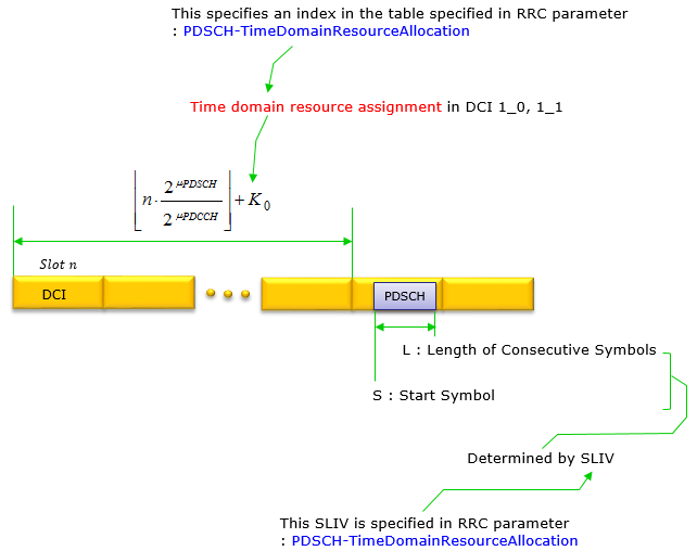
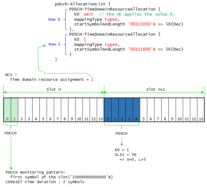
Following is the RRC parameters determining k0. SLIV determination is a pretty complicated process. so I created a separate page for this, refer to this page. PDSCH-TimeDomainResourceAllocation is an IE(Information Element) of PDSCH-Config and PDSCH-ConfigCommon. It is defined as an element (a kind of array element) of an IE called pdsch-AllocationList. Once this array(pdsch-AllocationList) is defined in RRC message, which elements of the array is used for each PDSCH scheduling is determined by the field called Time domain resource assignment in DCI 1_0 and DCI 1_1.
PDSCH-TimeDomainResourceAllocation ::= SEQUENCE {
k0 INTEGER(0..32) OPTIONAL, -- Need S
mappingType ENUMERATED {typeA, typeB},
startSymbolAndLength INTEGER (0..127) // SLIV
}
PDSCH-TimeDomainResourceAllocation-r16 ::= SEQUENCE {
k0-r16 INTEGER(0..32) OPTIONAL, -- Need S
mappingType-r16 ENUMERATED {typeA, typeB},
startSymbolAndLength-r16 INTEGER (0..127),
repetitionNumber-r16 ENUMERATED {n2, n3, n4, n5, n6, n7, n8, n16}
OPTIONAL,--Cond Formats1-0and1-1
...,
[[
k0-v1710 INTEGER(33..128) OPTIONAL -- Need S
]]
}
PDSCH-Config ::= SEQUENCE {
...
repetitionSchemeConfig-r16 SetupRelease { RepetitionSchemeConfig-r16} OPTIONAL -- Need M
]],
[[
repetitionSchemeConfig-v1630 SetupRelease { RepetitionSchemeConfig-v1630} OPTIONAL -- Need M
]],
...
}
RepetitionSchemeConfig-r16 ::= CHOICE {
fdm-TDM-r16 SetupRelease { FDM-TDM-r16 },
slotBased-r16 SetupRelease { SlotBased-r16 }
}
RepetitionSchemeConfig-v1630 ::= SEQUENCE {
slotBased-v1630 SetupRelease { SlotBased-v1630 }
}
FDM-TDM-r16 ::= SEQUENCE {
repetitionScheme-r16 ENUMERATED {fdmSchemeA, fdmSchemeB,tdmSchemeA },
startingSymbolOffsetK-r16 INTEGER (0..7) OPTIONAL -- Need R
}
SlotBased-r16 ::= SEQUENCE {
tciMapping-r16 ENUMERATED {cyclicMapping, sequentialMapping},
sequenceOffsetForRV-r16 INTEGER (1..3)
}
SlotBased-v1630 ::= SEQUENCE {
tciMapping-r16 ENUMERATED {cyclicMapping, sequentialMapping},
sequenceOffsetForRV-r16 INTEGER (0)
}
This example is based on 38.523-3 7.1.2.2.2.

This example is based on 38.523-3 7.1.2.2.2.
PDSCH - Ack/Nack Timing : K1
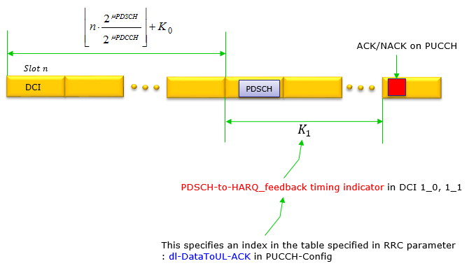
PDSCH-Ack/Nack Timing defines the time gap between PDSCH transmission and the reception of the PUCCH that carries ACK/NACK for the PDSCH.
Simply put, K1 indicates the time delay between PDSCH slot and UCI (Ack/Nack) slot
PUCCH-Config ::= SEQUENCE {
...
dl-DataToUL-ACK SEQUENCE (SIZE (8)) OF INTEGER (0..15) OPTIONAL, -- Need M
...
dl-DataToUL-ACK-r16 SetupRelease { DL-DataToUL-ACK-r16 }
...
dl-DataToUL-ACK-DCI-1-2-r16 SetupRelease { DL-DataToUL-ACK-DCI-1-2-r16}
}
DL-DataToUL-ACK-r16 ::= SEQUENCE (SIZE (1..8)) OF INTEGER (-1..15)
DL-DataToUL-ACK-DCI-1-2-r16 ::= SEQUENCE (SIZE (1..8)) OF INTEGER (0..15)
PUSCH - Time Domain Allocation : K2
Following is the illustration showing the Time Domain resource allocation for PUSCH based on 38.214 - 6.1.2.1 Resource allocation in time domain. When the subcarrier spacing of PUSCH and PDCCH is different, the time delay between DCI slot and PUSCH slot is a little bit complicated as shown below, but when the subcarrier spacing of PUSCH and PDCCH is same the time delay between DCI slot and PUSCH slot becomes K2.
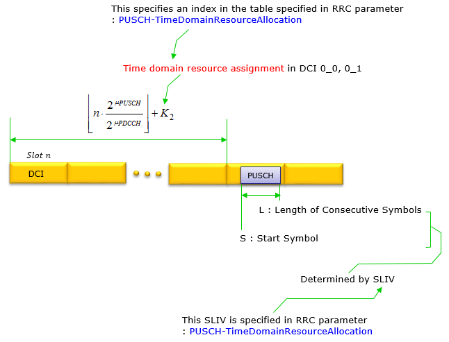
Following is the RRC parameters determining k2. SLIV determination is a pretty complicated process. so I created a separate page for this, refer to this page.
PUSCH-TimeDomainResourceAllocation ::= SEQUENCE {
k2 INTEGER (0..32)
mappingType ENUMERATED {typeA, typeB},
startSymbolAndLength INTEGER (0..127) // SLIV
}
PUSCH-TimeDomainResourceAllocation-r16 ::= SEQUENCE {
k2-r16 INTEGER(0..32) OPTIONAL, -- Need S
puschAllocationList-r16 SEQUENCE (SIZE(1..maxNrofMultiplePUSCHs-r16)) OF PUSCH-Allocation-r16,
...
}
PUSCH-Allocation-r16 ::= SEQUENCE {
mappingType-r16 ENUMERATED {typeA, typeB} OPTIONAL, -- Cond NotFormat01-02-Or-TypeA
startSymbolAndLength-r16 INTEGER (0..127) OPTIONAL, -- Cond NotFormat01-02-Or-TypeA
startSymbol-r16 INTEGER (0..13) OPTIONAL, -- Cond RepTypeB
length-r16 INTEGER (1..14) OPTIONAL, -- Cond RepTypeB
numberOfRepetitions-r16 ENUMERATED {n1, n2, n3, n4, n7, n8, n12, n16}
OPTIONAL, -- Cond Format01-02
...
}
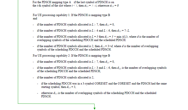
UE PDSCH Processing Procedure Time : N1
After UE completed the reception of PDSCH, it cannot send HARQ ACK/NACK right away because it needs some time to process the received data. The time span that UE requires to process the received PDSCH is called Tproc as shown in the following illustration and N1 is a major factor determining the Tproc. Roughly speaking, you can take N1 almost same as PDSCH processing time. Depending on the UE performance, this Tproc may vary (i.e, Tproc would be shorter with high performance UE comparing to poor performing UE). When network configures K1 and PUCCH location, it is important that the configuration gives enough time for UE to complete the process. That is, network should configure K1 and PUCCH in such that Tgap_symb is greater than Tproc.

FeatureSetDownlink-v1540 ::= SEQUENCE {
oneFL-DMRS-TwoAdditionalDMRS-DL ENUMERATED {supported} OPTIONAL,
additionalDMRS-DL-Alt ENUMERATED {supported} OPTIONAL,
twoFL-DMRS-TwoAdditionalDMRS-DL ENUMERATED {supported} OPTIONAL,
oneFL-DMRS-ThreeAdditionalDMRS-DL ENUMERATED {supported} OPTIONAL,
pdcch-MonitoringAnyOccasionsWithSpanGap SEQUENCE {
scs-15kHz ENUMERATED {set1, set2, set3} OPTIONAL,
scs-30kHz ENUMERATED {set1, set2, set3} OPTIONAL,
scs-60kHz ENUMERATED {set1, set2, set3} OPTIONAL,
scs-120kHz ENUMERATED {set1, set2, set3} OPTIONAL
} OPTIONAL,
pdsch-SeparationWithGap ENUMERATED {supported} OPTIONAL,
pdsch-ProcessingType2 SEQUENCE {
scs-15kHz ProcessingParameters OPTIONAL,
scs-30kHz ProcessingParameters OPTIONAL,
scs-60kHz ProcessingParameters OPTIONAL
} OPTIONAL,
pdsch-ProcessingType2-Limited SEQUENCE {
differentTB-PerSlot-SCS-30kHz ENUMERATED {upto1, upto2, upto4, upto7}
} OPTIONAL,
dl-MCS-TableAlt-DynamicIndication ENUMERATED {supported} OPTIONAL
}
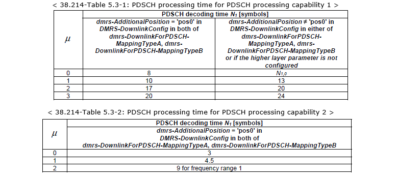
Indicates whether the UE supports PDSCH processing capability 2. The UE supports it only if all serving cells are self-scheduled and if all serving cells in one band on which the network configured processingType2 use the same subcarrier spacing. This capability signalling comprises the following parameters for each subcarrier spacing supported by the UE.
- fallback indicates whether the UE supports PDSCH processing capability 2 when the number of configured carriers is larger than numberOfCarriers for a reported value of differentTB-PerSlot. If fallback = 'sc', UE supports capability 2 processing time on lowest cell index among the configured carriers in the band where the value is reported, if fallback = 'cap1-only', UE supports only capability 1, in the band where the value is reported;
- differentTB-PerSlot indicates whether the UE supports processing type 2 for 1, 2, 4 and/or 7 unicast PDSCHs for different transport blocks per slot per CC; and if so, it indicates up to which number of CA serving cells the UE supports that number of unicast PDSCHs for different TBs. The UE shall include at least one of numberOfCarriers for 1, 2, 4 or 7 transport blocks per slot in this field if pdsch-ProcessingType2 is indicated.
Indicates whether the UE supports PDSCH processing capability 2 with scheduling limitation for SCS 30kHz. This capability signalling comprises the following parameter.
- differentTB-PerSlot-SCS-30kHz indicates the number of different TBs per slot.
The UE supports this limited processing capability 2 only if:
1) One carrier is configured in the band, independent of the number of carriers configured in the other bands;
2) The maximum bandwidth of PDSCH is 136 PRBs;
3) N1 based on Table 5.3-2 (shown above) for SCS 30 kHz.
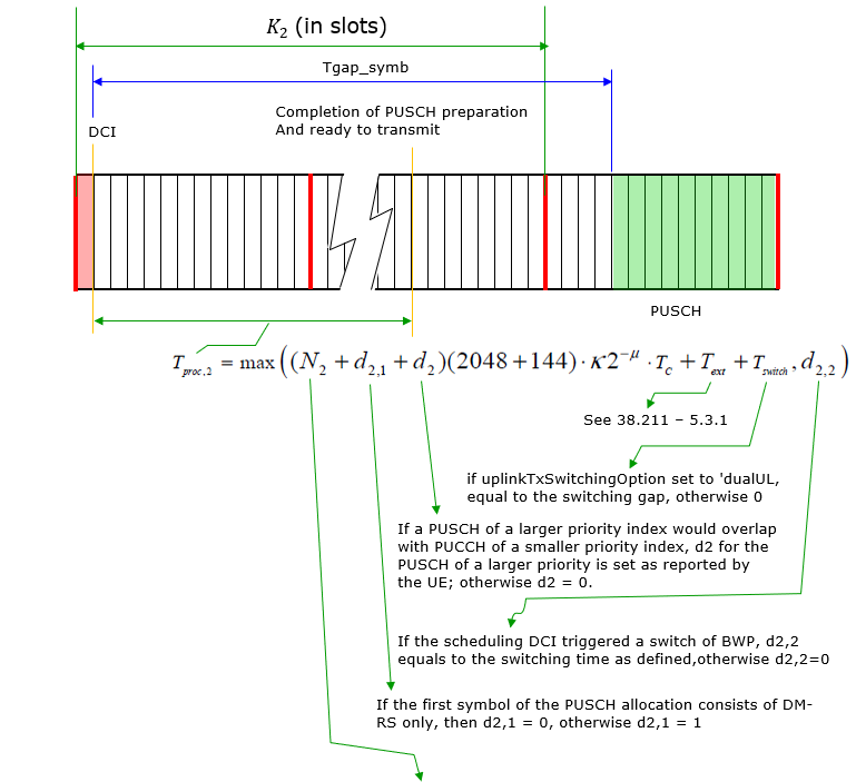
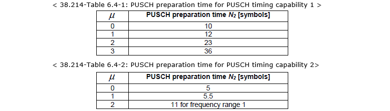
UE PUSCH preparation procedure time : N2
After UE recieved the UL Grant(DCI 0_x), it cannot send PUSCH right away because it needs some time to prrepare the PUSCH data. The time span that UE requires to prepare PUSCH is called Tproc as shown in the following illustration and N2 is a major factor determining the Tproc. Roughly speaking, you can take N2 almost same as PUSCH preparation time. Depending on the UE performance, this Tproc may vary (i.e, Tproc would be shorter with high performance UE comparing to poor performing UE). When network configures K2 and PUSCH location(i.e, PUSCH SLIV), it is important that the configuration gives enough time for UE to complete the preparation. That is, network should configure K2 and PUSCH in such that Tgap_symb is greater than Tproc.
phy-Parameters {
phy-ParametersCommon {
...
bwp-SwitchingDelay type1,
...
},
featureSetsDownlink {
{
...
pdsch-ProcessingType1-DifferentTB-PerSlot {
scs-15kHz upto2,
scs-30kHz upto2,
scs-60kHz upto2,
scs-120kHz upto2
},
...
FeatureSetUplink ::= SEQUENCE {
featureSetListPerUplinkCC SEQUENCE (SIZE (1.. maxNrofServingCells)) OF
FeatureSetUplinkPerCC-Id,
scalingFactor ENUMERATED {f0p4, f0p75, f0p8} OPTIONAL,
dummy3 ENUMERATED {supported} OPTIONAL,
intraBandFreqSeparationUL FreqSeparationClass OPTIONAL,
searchSpaceSharingCA-UL ENUMERATED {supported} OPTIONAL,
dummy1 DummyI OPTIONAL,
supportedSRS-Resources SRS-Resources OPTIONAL,
twoPUCCH-Group ENUMERATED {supported} OPTIONAL,
dynamicSwitchSUL ENUMERATED {supported} OPTIONAL,
simultaneousTxSUL-NonSUL ENUMERATED {supported} OPTIONAL,
pusch-ProcessingType1-DifferentTB-PerSlot SEQUENCE {
scs-15kHz ENUMERATED {upto2, upto4, upto7} OPTIONAL,
scs-30kHz ENUMERATED {upto2, upto4, upto7} OPTIONAL,
scs-60kHz ENUMERATED {upto2, upto4, upto7} OPTIONAL,
scs-120kHz ENUMERATED {upto2, upto4, upto7} OPTIONAL
} OPTIONAL,
dummy2 DummyF OPTIONAL
}
FeatureSetUplink-v1540 ::= SEQUENCE {
zeroSlotOffsetAperiodicSRS ENUMERATED {supported} OPTIONAL,
pa-PhaseDiscontinuityImpacts ENUMERATED {supported} OPTIONAL,
pusch-SeparationWithGap ENUMERATED {supported} OPTIONAL,
pusch-ProcessingType2 SEQUENCE {
scs-15kHz ProcessingParameters OPTIONAL,
scs-30kHz ProcessingParameters OPTIONAL,
scs-60kHz ProcessingParameters OPTIONAL
} OPTIONAL,
ul-MCS-TableAlt-DynamicIndication ENUMERATED {supported} OPTIONAL
}
FeatureSetUplink-v1610 ::= SEQUENCE {
pusch-RepetitionTypeB-r16 SEQUENCE {
maxNumberPUSCH-Tx-r16 ENUMERATED {n2, n3, n4, n7, n8, n12},
hoppingScheme-r16 ENUMERATED {interSlotHopping, interRepetitionHopping, both}
} OPTIONAL,
ul-CancellationSelfCarrier-r16 ENUMERATED {supported} OPTIONAL,
ul-CancellationCrossCarrier-r16 ENUMERATED {supported} OPTIONAL,
ul-FullPwrMode2-MaxSRS-ResInSet-r16 ENUMERATED {n1, n2, n4} OPTIONAL,
cbgPUSCH-ProcessingType1-DifferentTB-PerSlot-r16 SEQUENCE {
scs-15kHz-r16 ENUMERATED {one-pusch, upto2, upto4, upto7} OPTIONAL,
scs-30kHz-r16 ENUMERATED {one-pusch, upto2, upto4, upto7} OPTIONAL,
scs-60kHz-r16 ENUMERATED {one-pusch, upto2, upto4, upto7} OPTIONAL,
scs-120kHz-r16 ENUMERATED {one-pusch, upto2, upto4, upto7} OPTIONAL
} OPTIONAL,
cbgPUSCH-ProcessingType2-DifferentTB-PerSlot-r16 SEQUENCE {
scs-15kHz-r16 ENUMERATED {one-pusch, upto2, upto4, upto7} OPTIONAL,
scs-30kHz-r16 ENUMERATED {one-pusch, upto2, upto4, upto7} OPTIONAL,
scs-60kHz-r16 ENUMERATED {one-pusch, upto2, upto4, upto7} OPTIONAL,
scs-120kHz-r16 ENUMERATED {one-pusch, upto2, upto4, upto7} OPTIONAL
} OPTIONAL,
Reference
[1] 38.214 - 5G; NR; Physical layer procedures for data
[2] 38.331 - 5G; NR; Radio Resource Control (RRC); Protocol specification
[3] 38.523
[4] R1-1721515 : 3GPP TSG-RAN WG1 Meeting #91 Summary of DL/UL scheduling and HARQ management
[5] R1-1719401 : 3GPP TSG RAN WG1 Meeting 91 - Remaining issues on HARQ
[6] The impact of NR Scheduling Timings on End-to-End Delay for Uplink Traffic