Frequency domain allocation has to say which resource blocks a transmission uses, and there are two ways to say it. One sends a bitmap, which can describe any set of blocks at the cost of one bit per group. The other sends a start and a length, which is far shorter but can only describe a run of consecutive blocks. The box below states the choice, and the sections after it cover each type separately.
|
Resource Allocation Type in Detail
Resource Allocation Type indicates a method for resource allocation in frequency domain. Similar concept is used in LTE Resource Allocation as well. So if you are familiar with LTE Resource Allocation Type, you would easily understand the concepts on NR Resource Allocation Type.
- What kind of resource allocation types are supported ?
- How to determine Resource Allocation Type ?
- Allocation Type 0
- Allocation Type 1
- Dynamic Switch
- Reference
What kind of resource allocation types are supported ?
NR Resource Allocation Type is specified in the following specification. The downlink and the uplink are written up separately, and the two clauses define the same pair of schemes. The table further down places them against their LTE counterparts, because the numbering does not carry across.
- Downlink : 38.214 - 5.1.2.2 Resource allocation in frequency domain
- Uplink : 38.214 - 6.1.2.2 Resource allocation in frequency domain
Resource Allocation Type specifies the way in which the scheduler allocate resource blocks for each transmission. Just in terms of flexibility, the way to give the maximum flexibility of resource block allocation would be to use a string of a bit map (bit stream), each bit of which represent each resource block. This way you would achieve the maximum flexibility, but it would create too much complication of resource allocation process or too much data (too long bit map) to allocate the resources.
As mentioned above, LTE also use similar concept. Following table shows the comparision of NR and LTE Resource Allocation Type.
|
NR Resource Allocation Type |
LTE Resource Allocation Type |
Allocation Method |
| Bitmap | ||
|
N/A |
Bitmap | |
| Start RB and Number of RB | ||
| Set As per DCI field |
Two schemes and one switch : Type 0 and Type 1 are the schemes, and dynamicSwitch is not a third. It lets the DCI pick between the two per transmission.The numbering does not carry across from LTE : NR Type 1 is a start and a length, which LTE calls Type 2. The LTE Type 1 scheme has no NR counterpart.Type 0 can describe any set of groups : a bitmap costs one bit per resource block group, used or not.Type 1 costs far less to signal : a start and a length pack into one RIV. The allocation then has to be a single consecutive run.One clause pair covers both directions : 38.214 clause 5.1.2.2 defines the schemes for the downlink, and clause 6.1.2.2 defines them for the uplink.
How to determine Resource Allocation Type ?
According to 38.214 - 5.1.2.2, the Resource Allocation Type is determined implcitely by DCI format or by RRC layer message as described below. Two questions settle it, and they have to be asked in order. The DCI format comes first, because a fallback format fixes the answer on its own. Only when the format leaves the choice open does the RRC configuration decide.
-
The UE may assume that when the scheduling grant is received with
DCI format 1_0, 4_0 or 4_1 downlinkresource allocation type 1 is used. -
If the scheduling DCI is configured to indicated the downlink resource allocation type as part of the
Frequency-domainPDSCHresource field, the UE shall use downlinkresource allocation type 0 or type 1 as defined by this field. Otherwise the UE shall use the downlink frequency resource allocation type as defined by the RRC configured parameterResource-allocation-config for PDSCH.
How the Type is Signaled
Three things can carry the decision, and they sit at different levels. RRC names the scheme, and the DCI format can override that with a fallback rule. One bit inside the grant then settles it per transmission, when RRC asked for a switch.
The resource allocation type is not arbitrarily chosen—it’s explicitly configured or dynamically indicated. Here’s how it works:
The higher-layer parameter resourceAllocation in the PDSCH-Config (for downlink) or PUSCH-Config (for uplink) IE (Information Element) determines the resource allocation type. It can take one of three values:
- resourceAllocationType0: Only Type 0 (RB bitmap) is used.
- resourceAllocationType1: Only Type 1 (RIV) is used.
- dynamicSwitch: The type can switch dynamically between Type 0 and Type 1, and the choice is indicated in the DCI itself.
If resourceAllocation is set to resourceAllocationType0, the "Frequency domain resource assignment" field is always an RB bitmap. If set to resourceAllocationType1, it’s always an RIV.
The field is a single enumerated value, and it appears in more places than the paragraph above names. The listing below collects all of them, together with rbg-Size, which fixes how many resource blocks one bitmap bit stands for.
Following is based on
PDSCH-Config ::=                        SEQUENCE {
    ...
    resourceAllocation                      ENUMERATED { resourceAllocationType0, resourceAllocationType1, dynamicSwitch},
    ...
    rbg-Size                                ENUMERATED {config1, config2},
    ...,
    [[
    -- Release 16 : the compact format 1_2 gets a choice of its own
    resourceAllocationType1GranularityDCI-1-2-r16   ENUMERATED {n2,n4,n8,n16}                  OPTIONAL,   -- Need S
    ...
    resourceAllocationDCI-1-2-r16           ENUMERATED { resourceAllocationType0, resourceAllocationType1, dynamicSwitch}
                                                                                               OPTIONAL,   -- Need M
    ...
    ]],
    ...
}

PUSCH-Config ::=                        SEQUENCE {
    ...
    resourceAllocation                      ENUMERATED { resourceAllocationType0, resourceAllocationType1, dynamicSwitch},
    ...
    rbg-Size                                ENUMERATED { config2}                          OPTIONAL,   -- Need S
    ...,
    [[
    resourceAllocationDCI-0-2-r16           ENUMERATED { resourceAllocationType0, resourceAllocationType1, dynamicSwitch}
                                                                                               OPTIONAL,   -- Need M
    resourceAllocationType1GranularityDCI-0-2-r16   ENUMERATED { n2,n4,n8,n16 }                OPTIONAL,   -- Need S
    ...
    ]],
    ...
}

ConfiguredGrantConfig ::=               SEQUENCE {
    ...
    resourceAllocation                      ENUMERATED { resourceAllocationType0, resourceAllocationType1, dynamicSwitch },
    rbg-Size                                ENUMERATED {config2}                           OPTIONAL,   -- Need S
    ...
}

-- Release 18 added the multi-cell scheduling formats, each with its own copy again
PDSCH-ConfigDCI-1-3-r18 ::=             SEQUENCE {
    resourceAllocationDCI-1-3-r18           ENUMERATED {resourceAllocationType0, resourceAllocationType1, dynamicSwitch}
                                                                                               OPTIONAL,   -- Need M
    rbg-SizeDCI-1-3-r18                     ENUMERATED {config1, config2, config3, spare1} OPTIONAL,   -- Cond DCI-1-3
    resourceAllocationType1GranularityDCI-1-3-r18   ENUMERATED {n2,n4,n8,n16}                  OPTIONAL,   -- Need S
    numberOfBitsForRV-DCI-1-3-r18           INTEGER (0..2)                                     OPTIONAL,   -- Need R
    harq-ProcessNumberSizeDCI-1-3-r18       INTEGER (0..5)                                     OPTIONAL    -- Need R
}

PUSCH-ConfigDCI-0-3-r18 ::=             SEQUENCE {
    resourceAllocationDCI-0-3-r18           ENUMERATED {resourceAllocationType0, resourceAllocationType1, dynamicSwitch}
                                                                                               OPTIONAL,   -- Need M
    rbg-SizeDCI-0-3-r18                     ENUMERATED {config2, config3}                  OPTIONAL,   -- Need S
    resourceAllocationType1GranularityDCI-0-3-r18   ENUMERATED {n2,n4,n8,n16}                  OPTIONAL,   -- Need S
    numberOfBitsForRV-DCI-0-3-r18           INTEGER (0..2)                                     OPTIONAL,   -- Need R
    harq-ProcessNumberSizeDCI-0-3-r18       INTEGER (0..5)                                     OPTIONAL,   -- Need R
    uci-OnPUSCH-ListDCI-0-3-r18             SetupRelease { UCI-OnPUSCH-ListDCI-0-1-r16 }       OPTIONAL    -- Need M
}
The uplink cannot choose configuration 1 : rbg-Size is {config1, config2} in PDSCH-Config but only {config2} in PUSCH-Config. An uplink bitmap therefore uses the wider group.Release 18 added a third nominal size : rbg-SizeDCI-1-3-r18 reaches config3, which is a configuration the Nominal RBG size table above does not carry.Configured grants state the scheme themselves : ConfiguredGrantConfig carries its own resourceAllocation. A grant with no DCI still has to say how its allocation field is read.
When resourceAllocation is configured as dynamicSwitch, the specific DCI format used (e.g., 1_1 for downlink or 0_1 for uplink) includes a mechanism to indicate the type:
The most significant bit (MSB) of the "Frequency domain resource assignment" field is used as a flag:
- 0: Indicates Type 0 (RB bitmap). The remaining bits form the bitmap.
- 1: Indicates Type 1 (RIV). The remaining bits are interpreted as the RIV value.
This dynamic indication allows flexibility in scheduling, where the network can switch between contiguous (Type 1) and non-contiguous (Type 0) allocations based on the traffic needs.
For fallback DCI formats (e.g., DCI 1_0 for downlink or 0_0 for uplink), only Type 1 (RIV) is used. These formats are designed for simplicity and lower overhead, so they don’t support the bitmap-based Type 0 allocation. In this case, the "Frequency domain resource assignment" field is always interpreted as an RIV, and no dynamic switching is involved.
Practical Determination
The steps below are the ones to take against a live log, where the DCI format is known and the RRC configuration is available. They run in the order that settles the answer fastest.
To know whether the "Frequency domain resource assignment" field is an RIV or an RB bitmap:
Check the DCI Format: - If it’s a fallback format (e.g., DCI 1_0 or 0_0), it’s always RIV (Type 1).
- If it’s a non-fallback format (e.g., DCI 1_1 or 0_1), proceed to the next step.
Check the RRC Configuration: - Look at the resourceAllocation parameter in PDSCH-Config (for PDSCH) or PUSCH-Config (for PUSCH).
- If it’s resourceAllocationType0, the field is an RB bitmap.
- If it’s resourceAllocationType1, the field is an RIV.
- If it’s dynamicSwitch, examine the MSB of the "Frequency domain resource assignment" field in the DCI:
- MSB = 0: RB bitmap (Type 0).
- MSB = 1: RIV (Type 1).
Field Size: - The size of the "Frequency domain resource assignment" field can also provide a clue. For Type 0, the field size is determined by the number of RBGs in the BWP (e.g., ceiling(N_RB / RBG_size) bits). For Type 1, it’s based on the number of RBs in the BWP and the RIV formula (e.g., ceiling(log2(N_RB * (N_RB + 1) / 2)) bits). However, this is typically a secondary check after determining the type.
Allocation Type 0
In this type, we bundle multiple number of consecutive RBs into RBG(Resource Block Group) and allocate PDSCH / PUSCH only in the multiples of RBG. The number of RBs within a RBS varies depending on Bandwidth Part Size and Configuration as shown in the following table. The configuration type is determined by rbg-size field in PDSCH-Config in a RRC message. We specify the bitmap in DCI indicating the RBG number that carries PDSCH or PUSCH data. Since this is the bitmap, it is not required for the RBGs to be consecutive.
< 38.214 - Table 5.1.2.2.1-1: Nominal RBG size P, Table 6.1.2.2.1-1: Nominal RBG size P >
|
Bandwidth Part Size |
Configuration 1 |
Configuration 2 |
|
1 36 |
2 |
4 |
|
37 72 |
4 |
8 |
|
73 144 |
8 |
16 |
|
145 275 |
16 |
16 |
|
Bandwidth Size |
Bandwidth Size |
Bandwidth Size |
Bandwidth Size |
|||||
|
PRB # |
Config 1 |
Config 2 |
Config 1 |
Config 2 |
Config 1 |
Config 2 |
Config 1 |
Config 2 |
|
0 |
RBG 00 |
RBG 00 |
RBG 00 |
RBG 00 |
RBG 00 |
RBG 00 |
RBG 00 |
RBG 00 |
|
1 |
||||||||
|
2 |
RBG 01 |
|||||||
|
3 |
||||||||
|
4 |
RBG 02 |
RBG 01 |
RBG 01 |
|||||
|
5 |
||||||||
|
6 |
RBG 03 |
|||||||
|
7 |
||||||||
|
8 |
RBG 04 |
RBG 02 |
RBG 02 |
RBG 01 |
RBG 01 |
|||
|
9 |
||||||||
|
10 |
RBG 05 |
|||||||
|
11 |
||||||||
|
12 |
RBG 06 |
RBG 03 |
RBG 03 |
|||||
|
13 |
||||||||
|
14 |
RBG 07 |
|||||||
|
15 |
||||||||
|
16 |
RBG 08 |
RBG 04 |
RBG 04 |
RBG 02 |
RBG 02 |
RBG 01 |
RBG 01 |
RBG 01 |
|
17 |
||||||||
|
18 |
RBG 09 |
|||||||
|
19 |
||||||||
|
20 |
RBG 10 |
RBG 05 |
RBG 05 |
|||||
|
21 |
||||||||
|
22 |
RBG 11 |
|||||||
|
23 |
||||||||
|
24 |
RBG 12 |
RBG 06 |
RBG 06 |
RBG 03 |
RBG 03 |
|||
|
25 |
||||||||
|
26 |
RBG 13 |
|||||||
|
27 |
||||||||
|
28 |
RBG 14 |
RBG 07 |
RBG 07 |
|||||
|
29 |
||||||||
|
30 |
RBG 15 |
|||||||
|
31 |
||||||||
|
32 |
RBG 16 |
RBG 08 |
RBG 08 |
RBG 04 |
RBG 04 |
RBG 02 |
RBG 02 |
RBG 02 |
|
33 |
||||||||
|
34 |
RBG 17 |
|||||||
|
35 |
||||||||
|
36 |
RBG 09 |
|||||||
|
37 |
||||||||
|
38 |
||||||||
|
39 |
||||||||
|
40 |
RBG 10 |
RBG 05 |
RBG 05 |
|||||
|
41 |
||||||||
|
42 |
||||||||
|
43 |
||||||||
|
44 |
RBG 11 |
|||||||
|
45 |
||||||||
|
46 |
||||||||
|
47 |
||||||||
|
48 |
RBG 12 |
RBG 06 |
RBG 06 |
RBG 03 |
RBG 03 |
RBG 03 |
||
|
49 |
||||||||
|
50 |
||||||||
|
51 |
||||||||
|
52 |
RBG 13 |
|||||||
|
53 |
||||||||
|
54 |
||||||||
|
55 |
||||||||
|
56 |
RBG 14 |
RBG 07 |
RBG 07 |
|||||
|
57 |
||||||||
|
58 |
||||||||
|
59 |
||||||||
|
60 |
RBG 15 |
|||||||
|
61 |
||||||||
|
62 |
||||||||
|
63 |
||||||||
|
64 |
RBG 16 |
RBG 08 |
RBG 08 |
RBG 04 |
RBG 04 |
RBG 04 |
||
|
65 |
||||||||
|
66 |
||||||||
|
67 |
||||||||
|
68 |
RBG 17 |
|||||||
|
69 |
||||||||
|
70 |
||||||||
|
71 |
||||||||
|
72 |
RBG 09 |
|||||||
|
73 |
||||||||
|
74 |
||||||||
|
75 |
||||||||
|
76 |
||||||||
|
77 |
||||||||
|
78 |
||||||||
|
79 |
||||||||
|
80 |
RBG 10 |
RBG 05 |
RBG 05 |
RBG 05 |
||||
|
81 |
||||||||
|
82 |
||||||||
|
83 |
||||||||
|
84 |
||||||||
|
85 |
||||||||
|
86 |
||||||||
|
87 |
||||||||
|
88 |
RBG 11 |
|||||||
|
89 |
||||||||
|
90 |
||||||||
|
91 |
||||||||
|
92 |
||||||||
|
93 |
||||||||
|
94 |
||||||||
|
95 |
||||||||
|
96 |
RBG 12 |
RBG 06 |
RBG 06 |
RBG 06 |
||||
|
97 |
||||||||
|
98 |
||||||||
|
99 |
||||||||
|
100 |
||||||||
|
101 |
||||||||
|
102 |
||||||||
|
103 |
||||||||
|
104 |
RBG 13 |
|||||||
|
105 |
||||||||
|
106 |
||||||||
|
107 |
||||||||
|
108 |
||||||||
|
109 |
||||||||
|
110 |
||||||||
|
111 |
||||||||
|
112 |
RBG 14 |
RBG 07 |
RBG 07 |
RBG 07 |
||||
|
113 |
||||||||
|
114 |
||||||||
|
115 |
||||||||
|
116 |
||||||||
|
117 |
||||||||
|
118 |
||||||||
|
119 |
||||||||
|
120 |
RBG 15 |
|||||||
|
121 |
||||||||
|
122 |
||||||||
|
123 |
||||||||
|
124 |
||||||||
|
125 |
||||||||
|
126 |
||||||||
|
127 |
||||||||
|
128 |
RBG 16 |
RBG 08 |
RBG 08 |
RBG 08 |
||||
|
129 |
||||||||
|
130 |
||||||||
|
131 |
||||||||
|
132 |
||||||||
|
133 |
||||||||
|
134 |
||||||||
|
135 |
||||||||
|
136 |
RBG 17 |
|||||||
|
137 |
||||||||
|
138 |
||||||||
|
139 |
||||||||
|
140 |
||||||||
|
141 |
||||||||
|
142 |
||||||||
|
143 |
||||||||
|
144 |
RBG 09 |
RBG 09 |
||||||
|
145 |
||||||||
|
146 |
||||||||
|
147 |
||||||||
|
148 |
||||||||
|
149 |
||||||||
|
150 |
||||||||
|
151 |
||||||||
|
152 |
||||||||
|
153 |
||||||||
|
154 |
||||||||
|
155 |
||||||||
|
156 |
||||||||
|
157 |
||||||||
|
158 |
||||||||
|
159 |
||||||||
|
160 |
RBG 10 |
RBG 10 |
||||||
|
161 |
||||||||
|
162 |
||||||||
|
163 |
||||||||
|
164 |
||||||||
|
165 |
||||||||
|
166 |
||||||||
|
167 |
||||||||
|
168 |
||||||||
|
169 |
||||||||
|
170 |
||||||||
|
171 |
||||||||
|
172 |
||||||||
|
173 |
||||||||
|
174 |
||||||||
|
175 |
||||||||
|
176 |
RBG 11 |
RBG 11 |
||||||
|
177 |
||||||||
|
178 |
||||||||
|
179 |
||||||||
|
180 |
||||||||
|
181 |
||||||||
|
182 |
||||||||
|
183 |
||||||||
|
184 |
||||||||
|
185 |
||||||||
|
186 |
||||||||
|
187 |
||||||||
|
188 |
||||||||
|
189 |
||||||||
|
190 |
||||||||
|
191 |
||||||||
|
192 |
RBG 12 |
RBG 12 |
||||||
|
193 |
||||||||
|
194 |
||||||||
|
195 |
||||||||
|
196 |
||||||||
|
197 |
||||||||
|
198 |
||||||||
|
199 |
||||||||
|
200 |
||||||||
|
201 |
||||||||
|
202 |
||||||||
|
203 |
||||||||
|
204 |
||||||||
|
205 |
||||||||
|
206 |
||||||||
|
207 |
||||||||
|
208 |
RBG 13 |
RBG 13 |
||||||
|
209 |
||||||||
|
210 |
||||||||
|
211 |
||||||||
|
212 |
||||||||
|
213 |
||||||||
|
214 |
||||||||
|
215 |
||||||||
|
216 |
||||||||
|
217 |
||||||||
|
218 |
||||||||
|
219 |
||||||||
|
220 |
||||||||
|
221 |
||||||||
|
222 |
||||||||
|
223 |
||||||||
|
224 |
RBG 14 |
RBG 14 |
||||||
|
225 |
||||||||
|
226 |
||||||||
|
227 |
||||||||
|
228 |
||||||||
|
229 |
||||||||
|
230 |
||||||||
|
231 |
||||||||
|
232 |
||||||||
|
233 |
||||||||
|
234 |
||||||||
|
235 |
||||||||
|
236 |
||||||||
|
237 |
||||||||
|
238 |
||||||||
|
239 |
||||||||
|
240 |
RBG 15 |
RBG 15 |
||||||
|
241 |
||||||||
|
242 |
||||||||
|
243 |
||||||||
|
244 |
||||||||
|
245 |
||||||||
|
246 |
||||||||
|
247 |
||||||||
|
248 |
||||||||
|
249 |
||||||||
|
250 |
||||||||
|
251 |
||||||||
|
252 |
||||||||
|
253 |
||||||||
|
254 |
||||||||
|
255 |
||||||||
|
256 |
RBG 16 |
RBG 16 |
||||||
|
257 |
||||||||
|
258 |
||||||||
|
259 |
||||||||
|
260 |
||||||||
|
261 |
||||||||
|
262 |
||||||||
|
263 |
||||||||
|
264 |
||||||||
|
265 |
||||||||
|
266 |
||||||||
|
267 |
||||||||
|
268 |
||||||||
|
269 |
||||||||
|
270 |
||||||||
|
271 |
||||||||
|
272 |
RBG 17 |
RBG 17 |
||||||
|
273 |
||||||||
|
274 |
||||||||
Allocation Type 1
In this type, the resource is allocated to one or more consecutive RBs. The resource allocation area is defined by two parameters RB_Start and Number of Consecutive RBs within a specific BWP(BandWidth Part). When the resource allocation is specified in DCI, RB_Start and Number of Consecutive RBs within the BWP is combined into a specific single value called RIV(Resource Indicator Value).
When the resource allocation for type 1 is configured in DCI, it is specified as a specific number called RIV. RIV is a number to specify PDSCH or PUSCH resource allocation. In more intuitive form, we normally use two values (i.e, Number of RBs and Start RB) for the resource allocation. But with RIV, we can represent Number of RBs and Start RB in a single value. It would have some advantage in terms of number of bits to carry the information.. but it causes some confusion for us to convert RIV into Number of RBs and Start RB
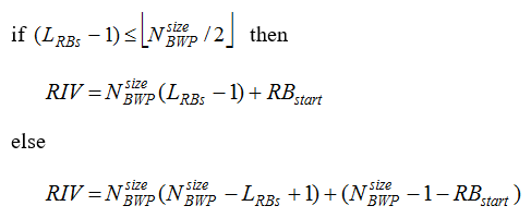
The RIV is calculated in following formula.
Downlink
The formula has two branches, and which one applies depends on whether the allocation is longer than half the bandwidth part. The branch exists so that every RIV maps to exactly one start and length pair, with no value wasted.
Uplink
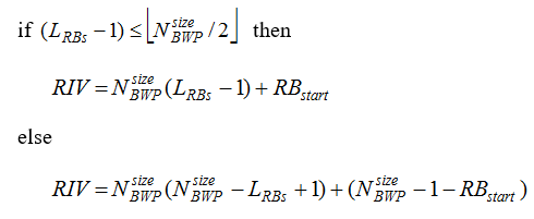
The uplink formula is the same as the downlink one, term for term. It is written out separately because 38.214 gives the uplink its own clause, not because the arithmetic differs.
One assumption inside the formula is worth stating, because a later release changed it. RB_start and L_RBs count resource blocks, so the RIV addresses the bandwidth part one block at a time. For the compact and the multi-cell DCI formats that is no longer always true.
When the grant arrives in DCI format 1_2 or 1_3, the type 1 field is a RIV over resource block groups rather than resource blocks. The group size comes from resourceAllocationType1GranularityDCI-1-2 or resourceAllocationType1GranularityDCI-1-3. Where neither is configured the size is 1, which restores the per block reading.
The formula has two branches : the first covers allocations up to half the bandwidth part, and the second covers the rest. Every RIV therefore decodes to exactly one pair.The uplink formula is the same as the downlink one : 38.214 gives each direction its own clause, and the arithmetic in the two is identical term for term.The size is the bandwidth part, not the carrier : the RIV is computed against the active bandwidth part. The same RIV names different blocks after a switch.DCI 1_2 and 1_3 can count in groups : for those formats the type 1 field is a RIV over resource block groups. The group size comes from the matching granularity parameter.A missing granularity means a group size of 1 : that recovers the per resource block reading. It still holds unless the parameter is configured.
Dynamic Switch
Whether to use Type 0 or Type 1 is determined by DCI at the time of each transmission. The bit that carries the decision is not a field of its own. It is the most significant bit of the frequency domain resource assignment, taken from the allocation field itself, so asking for a switch costs one bit of allocation range.
In 38.214-5.1.2.2, it is stated as follows.
If the scheduling DCI is configured to
In 38.212-7.3.1.2.2, it is stated as follows.
If both resource allocation type 0 and 1 are configured,
Example 01 > One configuration, three grants
The switch is easiest to follow when nothing else changes. One bandwidth part, one RRC configuration, and three consecutive grants that differ only in the frequency domain resource assignment field. The values below are invented, and every consequence under the drawing follows from the RBG table and the RIV formula above.
The sequence below runs from the reconfiguration that turns the switch on down to the third grant. Read the arrows as messages in time order, and read each shaded box as what the UE works out from the message immediately above it.
One bit at the front of the allocation field decides how the rest of it is read, and a fallback format never carries that bit.
The configuration never changes across the three grants : the same PDSCH-Config applies in all three slots, so the difference in outcome comes entirely from the DCI.13 RBGs comes from the bandwidth part and the table : a 51 RB part with rbg-Size config1 falls in the 37 to 72 row, so P is 4. Splitting 51 blocks into groups of four needs 13 groups.The last group is short : RBG 12 covers RB 48 to 50 rather than four blocks, because 51 is not a multiple of 4.Type 0 reached 15 blocks in three pieces : RBG 0, 5, 6 and 12 give 4 + 4 + 4 + 3 blocks. No single RIV could have described that shape.Type 1 reached 20 blocks in one piece : RIV 979 divides by 51 to give 19 and leaves 10, so the length is 20 and the start is 10.The fallback grant had no choice to make : DCI format 1_0 carries no flag, so slot n+2 is type 1 whatever resourceAllocation says.
Example 02 > The same UE reading two formats differently
A switch configured for one DCI format says nothing about another. Release 16 gave the compact formats their own copy of the parameter, and the two copies are set independently. This example holds everything else fixed and changes only the format the grant arrives in.
The sequence below shows two grants in consecutive slots, to the same UE, on the same bandwidth part. The allocation field is read one way in the first and another way in the second, and no reconfiguration happens in between.
Which parameter applies is decided by the DCI format, so one UE can be switching on one format and fixed on another at the same time.
Two parameters were configured, not one : resourceAllocation governs formats 1_1 and 0_1, and resourceAllocationDCI-1-2-r16 governs format 1_2.Only one of the two grants spends a flag bit : format 1_1 is on dynamicSwitch so its field starts with a flag, while format 1_2 is fixed to type 1 and has none.The same field value would mean different things : a leading 1 is a type indicator in the first grant and part of the RIV in the second.Release 18 repeated the pattern once more : resourceAllocationDCI-1-3-r18 and resourceAllocationDCI-0-3-r18 do the same job for the multi-cell formats.Granularity can change what the RIV counts : with resourceAllocationType1GranularityDCI-1-2 configured, the format 1_2 RIV counts resource block groups rather than blocks.
The choice is configured per DCI format rather than once for the cell. Release 16 gave the compact formats their own copy of the field, and Release 18 did the same for the multi-cell formats. A UE can therefore be configured for a bitmap on one format and a switch on another.
The flag is the MSB of the allocation field : it is not a separate DCI field, so a dynamicSwitch configuration spends one bit that would otherwise carry allocation.Zero means Type 0 and one means Type 1 : that first bit decides whether the remaining bits are a bitmap or a RIV.Each DCI format carries its own setting : resourceAllocation covers formats 1_1 and 0_1. The Release 16 pair covers 1_2 and 0_2, and the Release 18 pair covers 1_3 and 0_3.A fallback format never switches : DCI formats 1_0, 4_0 and 4_1 use resource allocation type 1 whatever resourceAllocation says.
Reference
[1] 38.214 - 5G; NR; Physical layer procedures for data. Clause 5.1.2.2 for the downlink and clause 6.1.2.2 for the uplink.
[2] 38.212 - 5G; NR; Multiplexing and channel coding. Clause 7.3.1.2.2 for the frequency domain resource assignment field.
[3] 38.331 - 5G; NR; Radio Resource Control (RRC); Protocol specification. PDSCH-Config, PUSCH-Config and ConfiguredGrantConfig.