|
BWP(Carrier Bandwidth Part) in Detail
This page is about another new concept in NR called BWP(BandWidth Part). BWP is a part of the total channel bandwidth configured for a cell that is used for a UE at a specific moment of operation. Usually a cell configures multiple BWPs out of the total channel bandwidth and select a specific one at each moment of operation. I think the purpose and concept of BWP is very similar to NarrowBand in LTE M1.
Definition of BWP
According to 38.211 4.4.5, A carrier bandwidth part is defined as follows :
Carrier Bandwidth Part is a contiguous set of physical resource blocks,selected from a contiguous subset of the common resource blocks for a given numerology(u) on a given carrier. It can be illustrated as below.
NOTE : Maximum 4 BWP can be specified in DL and UL. Following illustration is only an example showing the case of 3 BWP. (NOTE : CRB in this illustration stands for Carrier Resource Block which is numbered from the one end through the other end of Carrier Band (this is a kind of global resource block), the PRB stands for Physical Resource Block is the resource blocks numbered within each BWP).
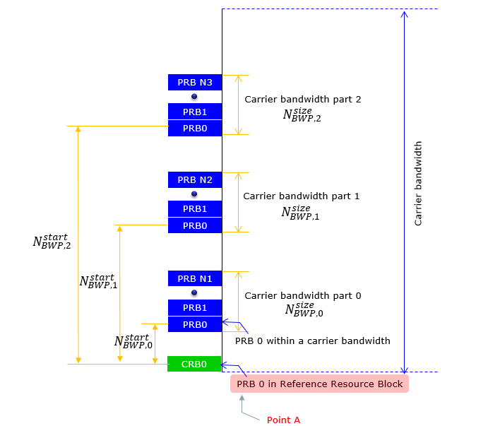
Point A indicates a common reference point for resource block grids and is obtained from the following higher-layer parameters as described in 38.211 - 4.4.4.2:
- PRB-index-DL-common for a PCell downlink represents the frequency offset between point A and the lowest subcarrier of the lowest resource block of the SS/PBCH block used by the UE for initial cell selection;
- PRB-index-UL-common for a PCell uplink in paired spectrum represents the frequency offset between point A and the frequency location based on ARFCN of the uplink indicated in SIB1;
- PRB-index-UL-common for a PCell uplink in unpaired spectrum represents the frequency offset between point A and the lowest subcarrier of the lowest resrouce block of the SS/PBCH block used by the UE for initial cell selection;
- PRB-index-DL-Dedicated for an SCell downlink represents the frequency offset between point A and the frequency location based on ARFCN in the higher-layer SCell configuration;
- PRB-index-UL-Dedicated for an SCell uplink represents the frequency offset between point A and the frequency location based on ARFCN in the higher-layer SCell configuration;
- PRB-index-SUL-common for a supplementary uplink represents the frequency offset between point A and the frequency location based on ARFCN in the higher-layer SUL configuration.
Carrier Bandwidth Part allocation for DL and UL
< Downlink >
- A UE can be configured with up to four carrier bandwidth parts
- The bandwidth of each BW should be equal or greater than SS Block BW, but it may or may not contain SS Block.
- Only one carrier bandwidth part can be active at a given time
- The UE is not expected to receive PDSCH, PDCCH, CSI-RS, or TRS outside an active bandwidth part.
- Each DL BWP include at least one CORESET with UE Specific Search Space (USS).
- In primary carrier, at least one of the configured DL BWPs includes one CORESET with common search space (CSS)
< Uplink >
- A UE can be configured with up to four carrier bandwidth parts
- Only one carrier bandwidth part can be active at a given time
- If a UE is configured with a supplementary uplink
- The UE can in addition be configured with up to four carrier bandwidth parts in the supplementary uplink
- Only one carrier bandwidth part can be active at a given time
- The UE shall not transmit PUSCH or PUCCH outside an active bandwidth part.
Mapping between nCRB and nPRB
nCRB indicates a resource block location in common resource block, nPRB indicates a resource block within a specific carrier bandwidth part. In other words, you can think of nCRB is a position in an absolute (reference) coordinate system and nPRB is a position in a relative coordinate system. The relationship between nCRB and nPRB is defined as follows (38.211 v2.0.0 - 4.4.4.4).
![]()
This can be illustrated as an example shown below.

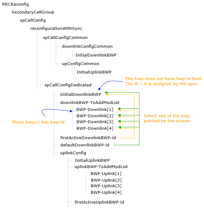
BWP types
There are several different types of BWPs : Initial BWP, firstActiveBWP, Default BWP and (regular) BWPs. These are defined in RRC message as follows. Regarding the role of each BWP, refer to the diagram in this section and RRC parameter description in this section.
< BWP configuration in ENDC RRCReconfig >
Using the basic types and configuration structure as shown above, you can take various options of BWP configuration as shown below.
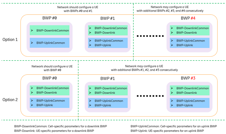
Source : A Primer on Bandwidth Parts in 5G New Radio
RRC Parameters for BandwidthPart Configuration
Following is based on 38.331 v15.7.0
ServingCellConfig ::= SEQUENCE {
    tdd-UL-DL-ConfigurationDedicated    TDD-UL-DL-ConfigDedicated   OPTIONAL,-- Cond TDD
    initialDownlinkBWP                  BWP-DownlinkDedicated  OPTIONAL,  -- Cond ServCellAdd
    downlinkBWP-ToReleaseList           SEQUENCE (SIZE (1..maxNrofBWPs)) OF BWP-Id  OPTIONAL,
    downlinkBWP-ToAddModList        SEQUENCE (SIZE (1..maxNrofBWPs)) OF BWP-Downlink OPTIONAL
    firstActiveDownlinkBWP-Id       BWP-Id      OPTIONAL,   -- Need R
    bwp-InactivityTimer         ENUMERATED {ms2, ms3, ms4, ms5, ms6, ms8, ms10, ms20,
                                            ms30, ms40,ms50, ms60, ms80, ms100, ms200,
                                            ms300, ms500, ms750, ms1280, ms1920, ms2560,
                                            spare10, spare9, spare8, spare7, spare6,
                                            spare5, spare4, spare3, spare2, spare1 } OPTIONAL,
    defaultDownlinkBWP-Id       BWP-Id      OPTIONAL,   -- Need M
    uplinkConfig                UplinkConfig    OPTIONAL, -- Cond ServCellAdd-UL
    supplementaryUplink         UplinkConfig    OPTIONAL, -- Cond ServCellAdd-SUL
    pdsch-ServingCellConfig     SetupRelease { PDSCH-ServingCellConfig } OPTIONAL, -- Need M
    csi-MeasConfig              SetupRelease { CSI-MeasConfig } OPTIONAL,   -- Need M
    carrierSwitching            SetupRelease { SRS-CarrierSwitching} OPTIONAL,  -- Need M
    sCellDeactivationTimer      ENUMERATED {ms20, ms40, ms80, ms160, ms200, ms240, ms320,
                                            ms400, ms480, ms520, ms640, ms720, ms840,
                                            ms1280, spare2,spare1} OPTIONAL,-- Cond
    .....
    }

maxNrofBWPs INTEGER ::= 4

UplinkConfig ::= SEQUENCE {
    initialUplinkBWP            BWP-UplinkDedicated OPTIONAL,   -- Cond ServCellAdd.
    uplinkBWP-ToReleaseList     SEQUENCE (SIZE (1..maxNrofBWPs)) OF BWP-Id OPTIONAL,-- Need N
    uplinkBWP-ToAddModList      SEQUENCE (SIZE (1..maxNrofBWPs)) OF BWP-Uplink  OPTIONAL,
    firstActiveUplinkBWP-Id     BWP-Id  OPTIONAL,   -- Need R
    pusch-ServingCellConfig     SetupRelease { PUSCH-ServingCellConfig } OPTIONAL,
    ...
}

BWP-Downlink ::= SEQUENCE {
    bwp-Id              BWP-Id,
    bwp-Common          BWP-DownlinkCommon
    bwp-Dedicated       BWP-DownlinkDedicated
    ...
}

BWP-DownlinkCommon ::=  SEQUENCE {
    genericParameters   BWP,
    pdcch-ConfigCommon  SetupRelease { PDCCH-ConfigCommon }
    pdsch-ConfigCommon  SetupRelease { PDSCH-ConfigCommon }
    ...
}

BWP-DownlinkDedicated ::= SEQUENCE {
    pdcch-Config            SetupRelease { PDCCH-Config }
    pdsch-Config            SetupRelease { PDSCH-Config }
    sps-Config          SetupRelease { SPS-Config }
    radioLinkMonitoringConfig   SetupRelease { RadioLinkMonitoringConfig }
    ...
}

BWP-Uplink ::= SEQUENCE {
    bwp-Id              BWP-Id,
    bwp-Common          BWP-UplinkCommon
    bwp-Dedicated       BWP-UplinkDedicated
    ...
}

BWP-UplinkCommon ::=    SEQUENCE {
    genericParameters   BWP,
    rach-ConfigCommon   SetupRelease { RACH-ConfigCommon }
    pusch-ConfigCommon  SetupRelease { PUSCH-ConfigCommon }
    pucch-ConfigCommon  SetupRelease { PUCCH-ConfigCommon }
    ...
}

BWP-UplinkDedicated ::=     SEQUENCE {
    pucch-Config                    SetupRelease { PUCCH-Config }               OPTIONAL,--Need M
    pusch-Config                    SetupRelease { PUSCH-Config }               OPTIONAL,--Need M
    configuredGrantConfig           SetupRelease { ConfiguredGrantConfig }      OPTIONAL,--Need M
    srs-Config                      SetupRelease { SRS-Config }                 OPTIONAL,--Need M
    beamFailureRecoveryConfig       SetupRelease { BeamFailureRecoveryConfig }  OPTIONAL,--Need M
    ...
}

BWP ::=     SEQUENCE {
    locationAndBandwidth        INTEGER (0..37949),
    subcarrierSpacing           SubcarrierSpacing,
    cyclicPrefix                ENUMERATED { extended }
}
If configured for an SpCell, this field contains the ID of the DL BWP to be activated upon performing the reconfiguration in which it is received. If the field is absent, the RRC reconfiguration does not impose a BWP switch (corresponds to L1 parameter 'active-BWP-DL-Pcell'). If configuredfor an SCell, this field contains the ID of the downlink bandwidth part to be used upon MAC-activation of an SCell. The initial bandwidth part is referred to by BWP-Id = 0
The NW may trigger the UE to swtich UL or DL BWP using a DCI field. The four code points in that DCI field map to the RRC-configured
- BWP-ID as follows: For up to 3 configured BWPs (in addition to the initial BWP) the DCI code point is equivalent to the BWP ID
- (initial = 0, first dedicated = 1, ...). If the NW configures 4 dedicated bandwidth parts, they are identified by DCI code
- points 0 to 3. In this case it is not possible to switch to the initial BWP using the DCI field.
- Corresponds to L1 parameter 'UL-BWP-index' / 'DL-BWP-index'.
How BWP are defined ?
As mentioned in Carrier Bandwidth Part allocation for DL and UL, maximum 4 BWPs can be defined in DL and UL. Each of BWP are configured by RRC messages as described in RRC Parameters for BandwidthPart Configuration.
How BWP location and bandwidth is specified in RRC ?
The location (starting position and the bandwidth of a BWP is specified in RRC parameter called locationAndBandwidth and this parameter is specified as RIV that can be calculated according to the following specification.
< 38.213-12 Bandwidth part operation > states as follows :
a first PRB and a number of contiguous PRBs by higher layer parameter locationAndBandwidth that is interpreted as RIV according to TS 38.214, setting ![]() , and the first PRB is a PRB offset relative to the PRB indicated by higher layer parameters offsetToCarrier and subcarrierSpacing
, and the first PRB is a PRB offset relative to the PRB indicated by higher layer parameters offsetToCarrier and subcarrierSpacing
< 38.214-5.1.2.2.2 Downlink resource allocation type 1> defines RIV as follows :
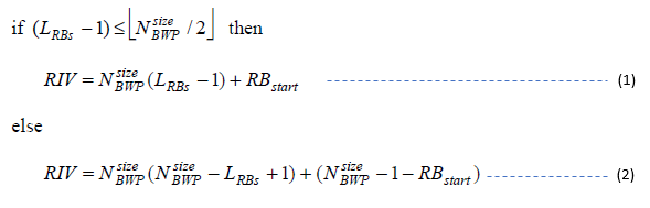
Combining the two specification mentioned above, I would come up with some examples as shown below. All these examples are based on the assumption that RB_start = 0, BWP takes up the maximum RB for the specified channel bandwidth and subcarrierspacing = 30 Khz, FR1
|
CBW |
max RB |
Equation |
RIV Calculation |
locationAndBandwidth |
|
5 |
11 |
(1) |
275*(11-1)+0 |
2750 |
|
10 |
24 |
(1) |
275*(24-1)+0 |
6325 |
|
15 |
38 |
(1) |
275*(38-1)+0 |
10175 |
|
20 |
51 |
(1) |
275*(51-1)+0 |
13750 |
|
25 |
65 |
(1) |
275*(65-1)+0 |
17600 |
|
30 |
78 |
(1) |
275*(78-1)+0 |
21175 |
|
40 |
106 |
(1) |
275*(106-1)+0 |
28875 |
|
50 |
133 |
(1) |
275*(133-1)+0 |
36300 |
|
60 |
162 |
(2) |
275*(275-162+1)+(275-1-0) |
31624 |
|
70 |
189 |
(2) |
275*(275-189+1)+(275-1-0) |
24199 |
|
80 |
217 |
(2) |
275*(275-217+1)+(275-1-0) |
16499 |
|
90 |
245 |
(2) |
275*(275-245+1)+(275-1-0) |
8799 |
|
100 |
273 |
(2) |
275*(275-273+1)+(275-1-0) |
1099 |
Following is the table that I calculated for subcarrier spacing = 15 Khz based on the assumption that RB_start = 0, BWP takes up the maximum RB for the specified channel bandwidth
|
CBW |
max RB |
Equation |
RIV Calculation |
locationAndBandwidth |
|
5 |
25 |
(1) |
275*(25-1)+0 |
6600 |
|
10 |
52 |
(1) |
275*(52-1)+0 |
14025 |
|
15 |
79 |
(1) |
275*(79-1)+0 |
21450 |
|
20 |
106 |
(1) |
275*(106-1)+0 |
28875 |
|
25 |
133 |
(1) |
275*(133-1)+0 |
36300 |
|
30 |
160 |
(2) |
275*(275-160+1)+(275-1-0) |
32174 |
|
40 |
216 |
(2) |
275*(275-216+1)+(275-1-0) |
16774 |
|
50 |
270 |
(2) |
275*(275-270+1)+(275-1-0) |
1924 |
Following is the table that I calculated for subcarrier spacing = 120 Khz based on the assumption that RB_start = 0, BWP takes up the maximum RB for the specified channel bandwidth
|
CBW |
max RB |
Equation |
RIV Calculation |
locationAndBandwidth |
|
50 |
32 |
(1) |
275*(32-1)+0 |
8525 |
|
100 |
66 |
(1) |
275*(66-1)+0 |
17875 |
|
200 |
132 |
(1) |
275*(132-1)+0 |
36025 |
|
400 |
264 |
(2) |
275*(275-264+1)+(275-1-0) |
3574 |
How a specific BWP is selected (BWP switching) ?
Even though multiple (max 4) BWPs can be defined in DL and UL, only one BWP can be active at each specific moment. It implies there is some mechainism to select a specific BWP as the active one. According to 38.321-5.15 Bandwidth Part (BWP) operation, BWP selection (or BWP switching) can be done by several different way
s as listed below.
- By PDCCH (i.e, DCI) : A specific BWP can be activated by Bandwidth part indicator in DCI Format 0_1 (a UL Grant) and DCI Format 1_1 (a DL Schedule)
- By the bwp-InactivityTimer : ServingCellConfig.bwp-InactivityTimer
- By RRC signalling
- By the MAC entity itself upon initiation of Random Access procedure
With using the mechanisums listed above, a specific BWP become active depending on various situations in the call processing.The switching process can be summarized in illustration as follows.
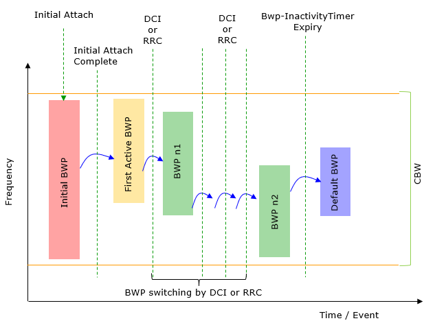
Another well presented illustration of BWP change/adaptation is shown below :
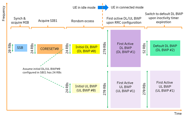
Source : A Primer on Bandwidth Parts in 5G New Radio
Followings are some of the examples of BWP switching for specific cases based on the statement in 3GPP specification. If you have overall understanding as shown above, following description would sound clearer to you.
if PRACH occasions are not configured for the active UL BWP:
For UL,set the active UL BWP = initialUplinkBWP;
For DL,
if the Serving Cell is a SpCell:
set the active DL BWP = initialDownlinkBWP.
if PRACH occasions are configured for the active UL BWP
For UL,set the active UL BWP = the configured UL BWP
For DL,
if the Serving Cell is a SpCell:
set the active DL BWP = DL BWP with the same bwp-Id as the active UL BWP.
Perform RACH procedure with the active BWP selected as above.
an initial DL BWP is defined by a location and number of contiguous PRBs, starting from a PRB with the lowest index and ending at a PRB with the highest index among PRBs of a CORESET for Type0-PDCCH CSS set, and a SCS and a cyclic prefix for PDCCH reception in the CORESET for Type0-PDCCH CSS set ==> It mean that the initialDlBWP takes up the full RBs defined in FrequencyInfoDL (i.e, Full RB in the CBW)
- Active BWP for DL = firstActiveDownlinkBWP-Id
- Active BWP for UL = firstActiveUplinkBWP-Id
"Reconfiguration with sync" is a common mechanism of activing NR cell in NSA (i.e, Adding NR Cell to LTE cell). In this case, Active BWP for DL and UL is set to be as follows .
Check if there is any on-going RACH procedure. If there is no on-going RACH procedure or RACH procedure is just completed by the received DCI (masked with C-RNTI).
set the active BWP = the BWP specified by the DCI
For unpaired spectrum operation, a DL BWP from the set of configured DL BWPs with index provided by BWP-Id is linked with an UL BWP from the set of configured UL BWPs with index provided by BWP-Id when the DL BWP index and the UL BWP index are same. ==> Simply put, DL BWP id = UL BWP id
For unpaired spectrum operation, a UE does not expect to receive a configuration where the center frequency for a DL BWP is different than the center frequency for an UL BWP when the BWP-Id of the DL BWP is same as the BWP-Id of the UL BWP ==> Simply put, Center frequency of DL BWP = Center Frequency of UL BWP
BWP Switching Delay
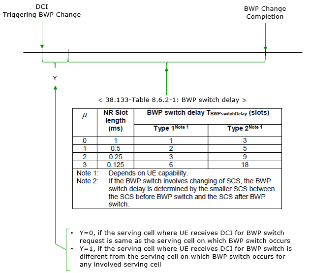
Changing BWP (Switching BWP) is the process of changing huge set of configurations. So it would need at least a certain amount of time to complete the switching. This time delay can be illustrated as follows based on 38.133-8.6.2
Time Delay for DCI based BWP switching
Time Delay for Timer based BWP switching

RRC for BWP Switching
ServingCellConfig ::= SEQUENCE {
...
firstActiveDownlinkBWP-Id BWP-Id
bwp-InactivityTimer ENUMERATED {ms2, ms3, ms4, ms5, ms6, ms8, ms10, ms20, ms30,
ms40,ms50, ms60, ms80,ms100, ms200,ms300, ms500,
ms750, ms1280, ms1920, ms2560, spare10, spare9, spare8,
spare7, spare6, spare5, spare4, spare3, spare2, spare1 } OPTIONAL,
...
UE Capability
Phy-ParametersCommon ::= SEQUENCE {
...
bwp-SwitchingDelay ENUMERATED {type1, type2} OPTIONAL,
bwp-SwitchingMultiCCs-r16 CHOICE {
type1-r16 ENUMERATED {us100, us200},
type2-r16 ENUMERATED {us200, us400, us800, us1000}
}
...
}
BandNR ::= SEQUENCE {
bwp-WithoutRestriction ENUMERATED {supported} OPTIONAL,
bwp-SameNumerology ENUMERATED {upto2, upto4} OPTIONAL,
bwp-DiffNumerology ENUMERATED {upto4} OPTIONAL,
...
}
Why BWP ?
When I first saw the descriptions on BWP, I asked myself 'why we need this ? We already has pretty flexible mechanism of changing Bandwidth dynamically. Just by changing the number of RBs and starting RB, we can change the operation bandwidth. Then, why we still need another mechanism of restricting bandwidth ?'.
The purpose of BWP is more for UE rather than for Network, especially for low end UEs which cannot afford to such a wideband operation.
In most case, NR would operate in very wideband and there wouldn't be any issues for the network (gNB) and high end UEs to handle the full operating band, but we cannot expect every types of UE to be able to work with this kind of wideband. So we need another special mechanism to tell some UEs 'Hey... we are operating in this wide band, but you don't need to worry about covering the full band. this is a fraction of spectrum you only need to care'. This is how (and why) we came out with the new concept called BWP. It would remind you of NarrowBand in LTE M1. (Refer to Ref[1] if you want to know more detailed stories on various alternatives on NR Wideband operation).
BWP Configuration Examples
Example 01 > Band78, CBW 20 Mhz
Following is an example configuration from Amarisoft. (NOTE : You may need additional knowledge about Coreset Bandwidth. Refer to this note for CORESET interpretation)

BWP Switching Operation Examples
NOTE : If you want to see the contents of full log with Amarisoft Log viewer, go to LogAnalysis section and click on 'Sample Log' in this tutorial of Amarisoft TechAcademy.
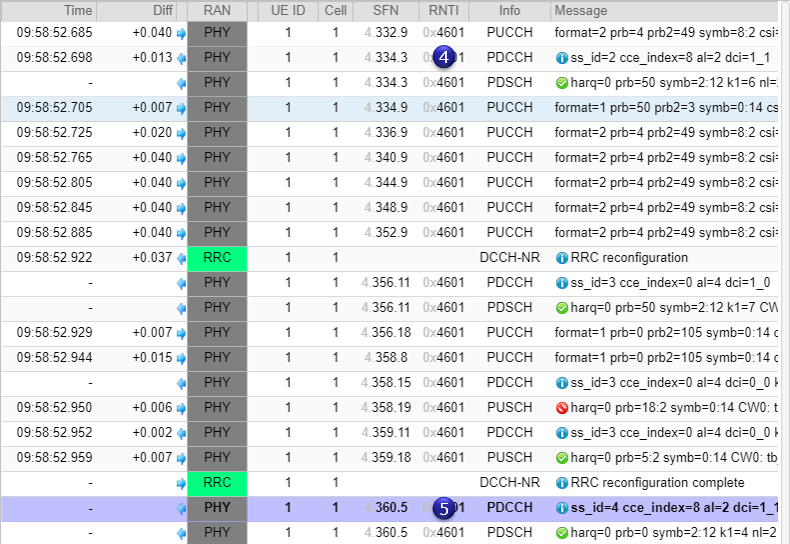
Example 1 > BWP Switching by DCI
This is an example from Amari Callbox with a commercial UE showing the BWP switching triggered by DCI.
[1] and [2] in the following RRC log is the places where all the BWP is configured.

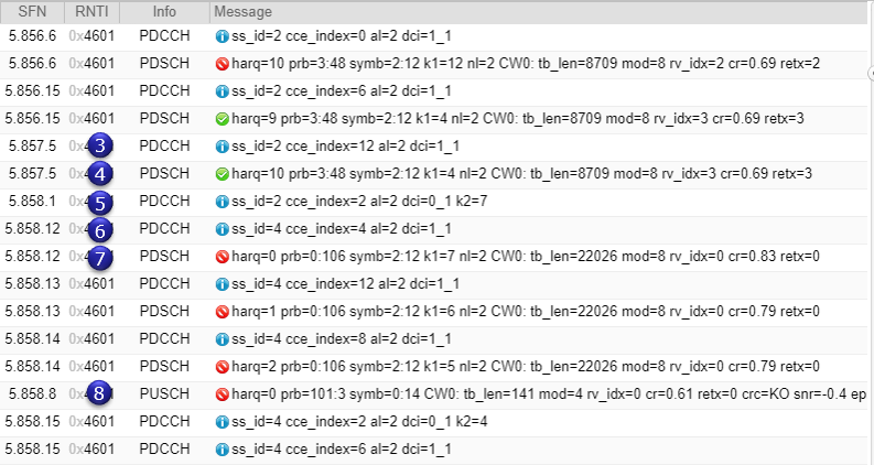
Following is the sequence of physical channels showing the PDCCH/PDSCH before and after BWP switching.
[1] SIB1
Check on this for full message.
message c1: systemInformationBlockType1: {
....
servingCellConfigCommon {
downlinkConfigCommon {
frequencyInfoDL {
frequencyBandList {
{
freqBandIndicatorNR 78
}
},
offsetToPointA 30,
scs-SpecificCarrierList {
{
offsetToCarrier 0,
subcarrierSpacing kHz30,
carrierBandwidth 106
}
}
},
initialDownlinkBWP { // DL BWP 0
genericParameters {
locationAndBandwidth 12928,
subcarrierSpacing kHz30
},
....
},
uplinkConfigCommon {
frequencyInfoUL {
scs-SpecificCarrierList {
{
offsetToCarrier 0,
subcarrierSpacing kHz30,
carrierBandwidth 106
}
}
},
initialUplinkBWP { // UL BWP 0
genericParameters {
locationAndBandwidth 12928,
subcarrierSpacing kHz30
},
....
}
[2] RrcSetup
Check on this for full message.
{
message c1: rrcSetup: {
rrc-TransactionIdentifier 0,
criticalExtensions rrcSetup: {
...
spCellConfig {
spCellConfigDedicated {
initialDownlinkBWP {
...
downlinkBWP-ToAddModList {
{
bwp-Id 1,
bwp-Common { // DL BWP 1
genericParameters {
locationAndBandwidth 28875,
subcarrierSpacing kHz30
},
...
bwp-Dedicated {
pdcch-Config setup: {
...
},
pdsch-Config setup: {
...
},
firstActiveDownlinkBWP-Id 0,
uplinkConfig {
initialUplinkBWP {
pucch-Config setup: {
..
},
...
},
uplinkBWP-ToAddModList {
{
bwp-Id 1,
bwp-Common {
genericParameters { // UL BWP 1
locationAndBandwidth 28875,
subcarrierSpacing kHz30
},
pusch-ConfigCommon setup: {
...
},
pucch-ConfigCommon setup: {
...
}
},
bwp-Dedicated {
pucch-Config setup: {
...
},
resourceToAddModList {
...
},
pusch-Config setup: {
...
},
firstActiveUplinkBWP-Id 0,
...
},
....
}
}
}
}
}
}
[3] PDCCH
Message: ss_id=2 cce_index=12 al=2 dci=1_1
Data:
bwp=0
rb_alloc=0x5f
time_domain_rsc=0
mcs1=21
ndi1=0
rv_idx1=3
harq_process=10
dai=0
tpc_command=1
pucch_rsc=0
harq_feedback_timing=4
antenna_ports=2
srs_request=0
dmrs_seq_init=0
[4] PDSCH
Message: harq=10 prb=3:48 symb=2:12 k1=4 nl=2 CW0: tb_len=8709 mod=8 rv_idx=3 cr=0.69 retx=3
[5] PDCCH
Message: ss_id=2 cce_index=2 al=2 dci=0_1 k2=7
Data:
bwp=1
rb_alloc=0x139
time_domain_rsc=0
mcs=9
ndi=1
rv_idx=0
harq_process=0
dai=3
tpc_command=1
antenna_ports=0
srs_request=0
dmrs_seq_init=0
ul_sch_indicator=1
[6] PDCCH
Message: ss_id=4 cce_index=4 al=2 dci=1_1
Data:
bwp=1
rb_alloc=0xd3
time_domain_rsc=0
mcs1=23
ndi1=0
rv_idx1=0
harq_process=0
dai=0
tpc_command=1
pucch_rsc=0
harq_feedback_timing=1
antenna_ports=2
srs_request=0
dmrs_seq_init=0
[7] PDSCH
Message: harq=0 prb=0:106 symb=2:12 k1=7 nl=2 CW0: tb_len=22026 mod=8 rv_idx=0 cr=0.83 retx=0
[8] PUSCH
Message: harq=0 prb=101:3 symb=0:14 CW0: tb_len=141 mod=4 rv_idx=0 cr=0.61 retx=0 crc=KO snr=-0.4 epre=-124.0 ta=8.8
Example 2 > BWP Switching by RRC
This is an example from Amari Callbox with Amari UEsim

[1] SIB1
Following is bwp related parts in SIB1. See this for the whole message.
{
message c1: systemInformationBlockType1: {
...
servingCellConfigCommon {
downlinkConfigCommon {
frequencyInfoDL {
frequencyBandList {
{
freqBandIndicatorNR 78
}
},
offsetToPointA 30,
scs-SpecificCarrierList {
{
offsetToCarrier 0,
subcarrierSpacing kHz30,
carrierBandwidth 106
}
}
},
initialDownlinkBWP {
genericParameters {
locationAndBandwidth 12928,
subcarrierSpacing kHz30
},
...
uplinkConfigCommon {
frequencyInfoUL {
scs-SpecificCarrierList {
{
offsetToCarrier 0,
subcarrierSpacing kHz30,
carrierBandwidth 106
}
}
},
initialUplinkBWP {
genericParameters {
locationAndBandwidth 12928,
subcarrierSpacing kHz30
},
...
}
[2] RrcSetup
Following is bwp related parameters in RrcSetup. See this for the whole message.
{
message c1: rrcSetup: {
rrc-TransactionIdentifier 0,
criticalExtensions rrcSetup: {
radioBearerConfig {
...
spCellConfig {
spCellConfigDedicated {
initialDownlinkBWP {
....
downlinkBWP-ToAddModList {
{
bwp-Id 1,
bwp-Common {
genericParameters {
locationAndBandwidth 28875,
subcarrierSpacing kHz30
},
....
firstActiveDownlinkBWP-Id 0,
....,
uplinkBWP-ToAddModList {
{
bwp-Id 1,
bwp-Common {
genericParameters {
locationAndBandwidth 28875,
subcarrierSpacing kHz30
},
....
firstActiveUplinkBWP-Id 0,
}
[3] RrcReconfiguration
{
message c1: rrcReconfiguration: {
rrc-TransactionIdentifier 0,
criticalExtensions rrcReconfiguration: {
nonCriticalExtension {
masterCellGroup {
cellGroupId 0,
spCellConfig {
spCellConfigDedicated {
firstActiveDownlinkBWP-Id 1,
uplinkConfig {
firstActiveUplinkBWP-Id 1
},
tag-Id 0
}
}
}
}
}
}
}
[4] PDCCH @ SFN = 334.3
Message: ss_id=2 cce_index=8 al=2 dci=1_1
Data:
bwp=0
rb_alloc=0x2f
time_domain_rsc=0
mcs1=9
ndi1=1
rv_idx1=0
harq_process=0
dai=0
tpc_command=1
pucch_rsc=0
harq_feedback_timing=2
antenna_ports=2
srs_request=0
dmrs_seq_init=0
[5] PDCCH @ SFN = 360.5
Message: ss_id=4 cce_index=8 al=2 dci=1_1
Data:
bwp=1
rb_alloc=0x0
time_domain_rsc=0
mcs1=9
ndi1=1
rv_idx1=0
harq_process=0
dai=0
tpc_command=1
pucch_rsc=0
harq_feedback_timing=4
antenna_ports=2
srs_request=0
dmrs_seq_init=0
Reference
[1] NR Wide Bandwidth Operations by Jeongho Jeon, Intel Corporation
[2] Impact of Bandwidth Part (BWP) Switching on 5G NR System Performance (Fuad Abinader et al, IEEE)
[3] A Primer on Bandwidth Parts in 5G New Radio
[4] 5G NR BWP Types and BWP Operations
YouTube
[1] BandWidth Part (BWP): A 5G feature for improving spectrum flexibility and power savings
[2] 5G Course - 5G Bandwidth Parts (5G Initial BWP Active BWP Default BWP)
|
|
|