|
Frequency domain configuration in NR is not one number. It is a chain of offsets, each measured from the one before it, and each counted in a unit that the previous step had to establish first. Meeting ssb-subcarrierOffset before Point A leaves a reader with no way to place it.
This page follows that chain from the bottom. It starts with the reference grid, reaches Point A, and then uses both to place the SS/PBCH block, CORESET 0 and a bandwidth part in turn. The parameters that carry each step are collected at the end.
- Frequency Domain Location in Detail
- Reference Subcarrier Spacing for FR1 and FR2
- PointA and Offset
- How are resource blocks actually numbered ?
- SSB Frequency Location in NSA/ENDC
- SSB Frequency Location in SA
- CORESET 0 Location in Frequency Domain
- BWP Frequency Location
- Parameters determining Frequency Domain Location
- Reference
Frequency Domain Location in Detail
As you know, NR use various types of subcarrier spacing (Numerology). In addition, it can use different subcarrier spacing within the same channel bandwidth depending on type of channel/signal (e.g, SSB, PDSCH etc) or BWP. Then the problem (confusing part) is how to specify the location of each resource blocks using differentsubcarrier spacing. We need some kind of reference coordinate system for this.
The difficulty is worth stating precisely, because it is what every parameter on this page exists to answer. A resource block index means nothing on its own. It only means something once the grid it belongs to is known, and NR carries several grids at once in the same channel.
38.211 clause 4.4.4 sets out the pieces. Clause 4.4.4.2 defines Point A, clause 4.4.4.3 defines common resource blocks, clause 4.4.4.4 defines physical resource blocks and clause 4.4.4.5 defines virtual resource blocks. One origin and three numberings is the whole of the coordinate system, and the sections below use all of them.
Two consequences follow, and both are easy to miss. A parameter counted in resource blocks needs its subcarrier spacing stated separately, because the same count spans different amounts of spectrum at 15 kHz and at 30 kHz. And a parameter measured from the SSB cannot be compared with one measured from Point A until the offset between the two is known.
The reference grid is a ruler, not a transmission : nothing is sent on it, and its only job is to give the other grids a common origin.Its spacing depends on the frequency range : 15 kHz in FR1 and 60 kHz in FR2, whatever spacing the channel itself uses.Point A is the origin of the common grid : 38.211 clause 4.4.4.2 defines it, and every subcarrier spacing puts its CRB 0 there.Offsets are chained, not absolute : ssb-subcarrierOffset is measured from a common resource block boundary, which is itself measured from Point A.NSA and SA answer the question differently : NSA names the SSB frequency directly, and SA builds it up from Point A.
Reference Subcarrier Spacing for FR1 and FR2
In NR, there are two different type of reference coordinate system and these reference coordinate system is called Reference PRB. In sub 6 Ghz(FR1), we use the reference PRB system based on 15 Khz subcarrier spacing and in mmWave(FR2) we use the reference PRB sysbem based on on 60 khz subcarrier spacing as illustrated below.
Two channel bandwidths are drawn side by side, one for FR1 and one for FR2. The grid inside each is the reference PRB grid, and the two use different subcarrier spacings. In FR1 each reference PRB is 12 subcarriers of 15 kHz, so the lines are close together. In FR2 each is 12 subcarriers of 60 kHz, so far fewer fit across the same picture. PRB0, PRB1 and PRB2 are labelled at the bottom of each grid, and the dashed arrow marks both as the reference PRB.
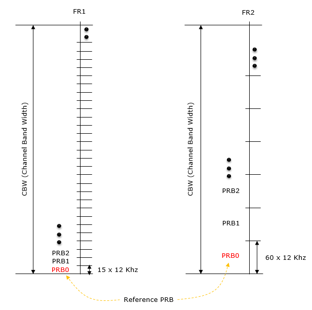
Figure 1. The reference grid is not the grid a channel is transmitted on. It is the ruler that every other grid is measured against, and FR1 and FR2 use different rulers.
Point A and Offset
This kind of common reference point shown above is represented as a specific term named as 'PointA' in 3GPP. The PointA is defined in 38.211 - 4.4.4.2 as follows.
offsetToPointA for a PCell downlink represents the frequency offset between point A and the lowest subcarrier of the lowest resource block of the SS/PBCH block used by the UE for initial cell selection, expressed in units of resource blocks assuming 15 kHz subcarrier spacing for FR1 and 60 kHz subcarrier spacing for FR2; absoluteFrequencyPointA for all other cases where absoluteFrequencyPointA represents the frequency-location of point A expressed as in ARFCN.
For example, let's assume that we configure SSB with 30 Khz subcarrier spacing in FR1. We can configure the frequency domain location of SSB in Reference PRB coordinate as shown below and the position can be informed to UE via signaling message.
The left column is the FR1 reference grid from Figure 1, still at 15 kHz. The block on the right is an SSB using 30 kHz subcarrier spacing, so its resource blocks are twice as tall. A horizontal line marks the reference location of the SSB, which is the lowest subcarrier of its lowest resource block. The yellow arrow runs from PRB0 up to that line. The label beside it says the offset is counted in whole PRBs and is signalled to the UE.
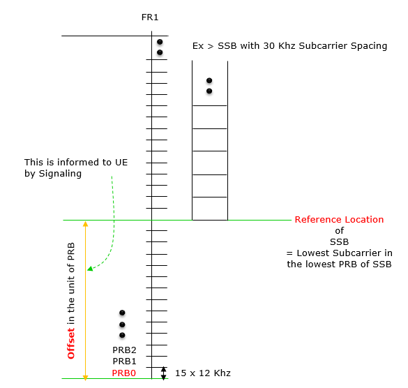
Figure 2. The offset is what connects two grids that use different subcarrier spacings. Without it the SSB grid and the reference grid have no common origin.
How are resource blocks actually numbered ?
Everything above counts resource blocks, and the counting restarts more than once. NR has three separate resource block numberings, and the figures on this page use all three without naming them. I lost time to this more than once, so it is worth setting out before the SSB and CORESET sections.
Common resource blocks are the absolute grid. They are numbered from 0 upward, and the centre of subcarrier 0 of CRB 0 coincides with Point A. There is one CRB grid per subcarrier spacing, and every one of them starts at the same Point A. That shared origin is the reason Point A exists. It is what keeps a 15 kHz grid and a 30 kHz grid aligned to each other.
Physical resource blocks are numbered inside a bandwidth part, from 0 to one less than the size of that part. The two numberings are related by one addition. A PRB index plus the starting CRB of the bandwidth part gives the CRB index. This is why a grant that says PRB 5 means nothing on its own, and why the BWP configuration has to be known first.
Virtual resource blocks are also numbered inside a bandwidth part, and they are what a scheduling grant allocates. They are then mapped to physical resource blocks, either directly or through an interleaver. Non-interleaved mapping means VRB n is PRB n. Interleaved mapping spreads a contiguous VRB allocation across the band. A small allocation then gets frequency diversity it would not otherwise have. The PDSCH page covers the mapping itself.
|
Numbering |
Numbered from |
How far it runs |
What uses it |
|
Common RB |
Point A, which is CRB 0 |
across the whole carrier, one grid per subcarrier spacing |
offsetToPointA, the BWP start, CORESET 0 |
|
Physical RB |
the first RB of a bandwidth part |
0 to the BWP size minus 1 |
the actual position of a transmission |
|
Virtual RB |
the first RB of a bandwidth part |
0 to the BWP size minus 1 |
what a DCI resource allocation field counts |
One consequence explains a detail in the figures above. CORESET 0 is placed relative to the SSB rather than relative to Point A, and Figure 7 shows the arrow ending on the bottom of the SSB. That is not an inconsistency. A UE looking for CORESET 0 has found an SSB. It has not yet read the system information that carries offsetToPointA, so the SSB is the only reference it has.
Three numberings, one origin : Common, physical and virtual resource blocks all exist at once. Only the common grid is anchored to Point A.Point A is a shared origin, not a carrier edge : Its purpose is to keep grids of different subcarrier spacings aligned. It does not have to fall inside the carrier.A PRB index is meaningless without its bandwidth part : Add the starting common RB of the BWP to a PRB index and the absolute position appears.A grant counts virtual resource blocks : The DCI allocates VRBs, and the mapping to PRBs decides whether the allocation stays contiguous in frequency.CORESET 0 is measured from the SSB, not from Point A : At that point in the acquisition the UE has no Point A yet, so the SSB is the only origin available.
SSB Frequency Location in NSA/ENDC
The illustration shown below is based on the following statement on absoluteFrequencySSB from 38.331. As you may notice, there is slight differences between the two versions. The biggest difference is the part in red. The illustration shown below is based on v15.2.1.
38.331 V15.2.1 (2018-06)
Frequency of the SSB to be used for this serving cell.
38.331 V15.5.1 (2019-05)
Frequency of the SSB to be used for this serving cell. SSB related parameters (e.g. SSB index) provided for a serving cell refer to this SSB frequency unless mentioned otherwise. The cell-defining SSB of the PCell is always on the sync raster. Frequencies are considered to be on the sync raster if they are also identifiable with a GSCN value(TS 38.101-1). If the field is absent, the SSB related parameters should be absent, e.g. ssb-PositionsInBurst, ssb-periodicityServingCell and subcarrierSpacing in ServingCellConfigCommon IE. If the field is absent, the UE obtains timing reference from the SpCell. This is only supported in case the Scell is in the same frequency band as the SpCell.
The SSB is drawn as twenty resource blocks, numbered RB0 at the bottom to RB19 at the top, inside the carrier bandwidth. One arrow points at RB10 and at nothing else. The note on the left says that absoluteFrequencySSB, expressed in ARFCN, gives the position of resource element 0 of that resource block.
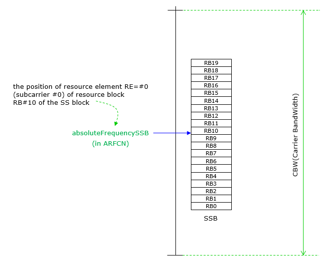
Figure 3. In NSA the SSB is located directly, with no reference to Point A at all. One ARFCN value names subcarrier 0 of RB10, and the rest of the SSB follows from it.
SSB Frequency Location in SA
Standalone operation cannot borrow a reference from an LTE anchor, so the SSB frequency has to be reconstructed rather than read. The UE finds the SSB on the synchronization raster first, then works downward to Point A using two offsets from system information. Three specifications are involved, and each contributes one link in that chain.
PointA is defined in 38.211 - 4.4.4.2 as follows.
Point A serves as a common reference point for resource block grids and is obtained from: offsetToPointA for a PCell downlink represents the frequency offset between point A and the lowest subcarrier of the lowest resource block of the SS/PBCH block used by the UE for initial cell selection, expressed in units of resource blocks assuming 15 kHz subcarrier spacing for FR1 and 60 kHz subcarrier spacing for FR2; absoluteFrequencyPointA for all other cases where absoluteFrequencyPointA represents the frequency-location of point A expressed as in ARFCN.
AbsoluteFrequencyPointA is defined by 38.331 (v15.7) as follow.
GSCN is with reference to the center frequency of SSB based on the statement in 38.104 - 5.4.3.2.
< 38.104 v15.7 - Table 5.4.3.2-1: Synchronization Raster to SS block Resource Element Mapping >
The table is two rows deep and one column wide. Resource element index k is 0. The physical resource block number of the SS block is 10.

Figure 4. This is what fixes the RB10 in the previous figure. The synchronization raster points at subcarrier 0 of resource block 10 of the SS block, and not at the bottom of it.
I assume that both GCSN and SSB_REF are with the reference to the center frequency of SSB based on the statement in 38.104 - 5.4.3.2.
< 38.104 v15.7 - Table 5.4.3.1-1: GSCN parameters for the global frequency raster >
Three frequency ranges, each with its own formula for the SS block frequency position and its own range of GSCN. Below 3000 MHz the position is N times 1200 kHz plus M times 50 kHz, with GSCN from 2 to 7498. From 3000 to 24250 MHz it is 3000 MHz plus N times 1.44 MHz, with GSCN from 7499 to 22255. Above that it is 24250.08 MHz plus N times 17.28 MHz. The note gives 3 as the default value of M for operating bands with an SCS spaced channel raster.
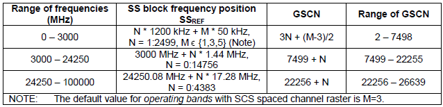
Figure 5. The synchronization raster is far coarser than the channel raster, and deliberately so. A UE searching for a cell only has to test the frequencies this table can generate.
That table has since gained company. In 38.104 v20.0.0 it is titled Table 5.4.3.1-1, GSCN parameters for the global frequency raster for above 3 MHz channel bandwidth, and two more tables sit beside it. Table 5.4.3.1-2 covers a 3 MHz channel bandwidth, and Table 5.4.3.1-3 adds parameters for band n100. The three rows shown above are unchanged.
Putting all the statements mentioned above, I can illustrate the SSB position and PointA, OffsetToPointA,ssb-subcarrierOffset as follows.
This is the SSB of Figure 3, now measured from below. The lowest line carries all three names of the same point, which are AbsoluteFrequencyPointA from 38.331, Point A from 38.211, and Common RB0. A green arrow spans from there to N_CRB^SSB, which is offsetToPointA. A shorter arrow above it is k_SSB, which is ssb-subcarrierOffset, and it reaches RB0 of the SSB. SSB_REF and GSCN still point at RB10.
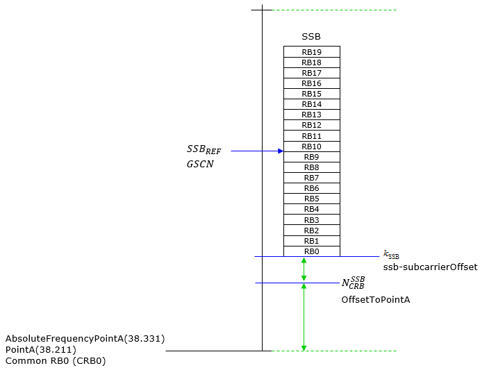
Figure 6. In SA the SSB position is built up from Point A in two steps, a whole number of resource blocks and then a number of subcarriers. That is why both offsetToPointA and ssb-subcarrierOffset exist.
Assuming followings are given
(1) GSCN (ARFCN)
(2) k_SSB
(3) OffsetToPointA
Step 1 : Convert (1) into the frequency in Mhz and assign it to (A)
Step 2 : Calculate the SSB Reference Location(subcarrier 0 in RB0 of SSB) in Mhz and store it to (B)
(B) = (A) - (10 x 12 x 0.03)
Step 3 : Calculate Point A in the form of frequency in Mhz using following equation and assign it to (C)
(C) = (B) - (k_SSB x 0.015) - ((3) x 12 x 0.015)
Step 4 : Convert (C) into ARFCN
38.211-4.4.4.2 states 'offsetToPointA for a PCell downlink represents the frequency offset between point A and the lowest subcarrier of the lowest resource block overlapping with the SS/PBCH block used by the UE for initial cell selection, expressed in units of resource blocks assuming 15 kHz subcarrier spacing for FR1 and 60 kHz subcarrier spacing for FR2'.
Now let's practice the example 1 with concrete numbers. Let's assume that we are given following numbers
(1) GSCN (ARFCN) = 7811 (629952)
(2) k_SSB = 0
(3) OffsetToPointA = 30
Step 1 : Convert (1) into the frequency in Mhz and assign it to (A)
GSCN (ARFCN) = 7811 (629952) ==> 3449.28 Mhz
Step 2 : Calculate the SSB Reference Location(subcarrier 0 in RB0 of SSB) in Mhz and store it to (B)
(B) = (A) - (10 x 12 x 0.03)
= 3449.28 - (10 x 12 x 0.03)
= 3445.68
Step 3 : Calculate Point A in the form of frequency in Mhz using following equation and assign it to (C)
(C) = (B) - (k_SSB x 0.015) - ((3) x 12 x 0.015)
= 3445.68 - (0 x 0.015) - (30 x 12 x 0.015)
= 3440.28
Step 4 : Convert (C) into ARFCN
3440.28 Mhz ==> 629352
Note : I used this site to get this number
CORESET 0 Location in Frequency Domain
Note where the offset is measured from, because it is not Point A. At the moment a UE needs CORESET 0 it has decoded the MIB and nothing more, so system information has not arrived and offsetToPointA is still unknown. The only reference it holds is the SSB it just found.
The two ends of the offset are worth reading carefully. It runs from the smallest resource block index of CORESET 0 up to the smallest index of the common resource block that overlaps the first resource block of the SSB. The upper end is therefore a common resource block boundary, and not the lowest subcarrier of the SSB itself.
The CORESET 0 Location in frequency domain is determined based on following statement in 38.213.
- k_ssb : always 15 Khz subcarrier spacing for FR1, 60 Khz subcarrier spacing for FR2 regardless of SSB subcarrier spacing.
- OffsetToPointA : the unit of this parameter is number of RB. Subcarrier spacing within this RB is always 15 Khz subcarrier spacing for FR1, 60 Khz subcarrier spacing for FR2 regardless of SSB subcarrier spacing.
- SSB Subcarrier Spacing : this varies depending on subCarrierSpacingCommon value in MIB. It can be summarized as follows.
- When subCarrierSpacingCommon = scs15or60,
- SSB Subcarrier Spacing for FR1 = 15 Khz
- SSB Subcarrier Spacing for FR2 = 60 Khz
- When subCarrierSpacingCommon = scs30or120,
- SSB Subcarrier Spacing for FR1 = 30 Khz
- SSB Subcarrier Spacing for FR2 = 120 Khz
One detail in that statement has widened. 38.213 v19.4.0 describes the CORESET 0 configuration in Tables 13-0 through 13-10 rather than 13-1 through 13-10. It also adds Tables 13-1A and 13-4A for shared spectrum channel access in FR1, and Table 13-10A for FR2-2. The offset column that this section is about behaves the same way in all of them.
Based on this statement, I illustrate the CORESET 0 position as shown below.
This is Figure 6 with CORESET 0 added as the orange bar on the left. A red arrow marks the offset to its lower edge, and the label gives tables 13-1 to 13-10 of 38.213 as the source. Everything on the right is unchanged, including the SSB blocks, offsetToPointA, ssb-subcarrierOffset and Point A. Notice which line the red arrow ends on. It ends on the bottom of the SSB, not on Point A.
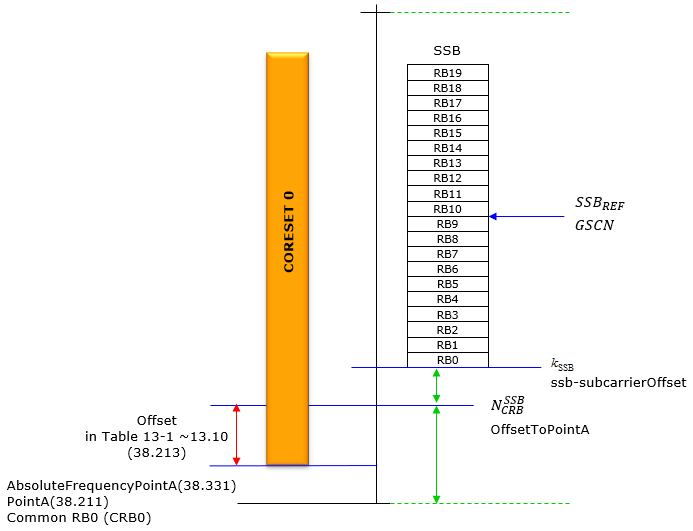
Figure 7. CORESET 0 is positioned relative to the SSB rather than to Point A. A UE has already found the SSB by the time it needs CORESET 0, and it has not yet read anything that would give it Point A.
BWP Frequency Location
A bandwidth part is the simplest case on this page, and for one reason. It is always a contiguous run of common resource blocks, so a start and a length describe it completely. No subcarrier level offset is needed, because a bandwidth part begins on a resource block boundary of its own grid.
The location and size of a BWP are specified in the RRC (Radio Resource Control) layer using several parameters, including AbsoluteFrequencyPointA, LocationAndBandwidth
The BWP is the grey block on the right. Two arrows define it. The long one runs from Common RB0 up to the bottom of the block, and it is the starting resource block. The short one beside the block is the number of consecutive resource blocks. Both are carried by one parameter, locationAndBandwidth, encoded as an RIV.
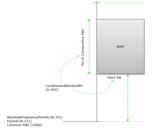
Figure 8. A bandwidth part needs only a start and a length, because it is always contiguous. Packing both into a single RIV is what keeps the field small enough to repeat in every configuration.
As illustrated above, BWP location is specified by two parameters : AbsoluteFrequencyPointA and LocationAndBandwidth. Brief description of these two parameters are :
AbsoluteFrequencyPointA : This parameter defines the absolute frequency of the first subcarrier in the lowest frequency band of the common resource blocks (CRBs) in the channel band.LocationAndBandwidth : This parameter is used to define both the location(starting position) and the bandwidth of the BWP. It is encoded using a single integer value which is calculated from the two values (i.e, startRB and lcrb(the number of contiguous RBs)).
Parameters determining Frequency Domain Location
There are many different RRC parameters determining Frequency Domain Location as listed below. But not all of them are used all at the same time. Depending on situation, the different set of parameters are used. When you try to set these frequency related parameters, you may ask to yourself a few questions as below.
- Do I want to setup frequency configuration in NSA or SA ?
- Do I want to setup SSB frequency ? or BWP frequency ?
Following is based on
FrequencyInfoDL ::=                 SEQUENCE {
    absoluteFrequencySSB                ARFCN-ValueNR                                                   OPTIONAL,   -- Cond SpCellAdd
    frequencyBandList                   MultiFrequencyBandListNR,
    absoluteFrequencyPointA             ARFCN-ValueNR,
    scs-SpecificCarrierList             SEQUENCE (SIZE (1..maxSCSs)) OF SCS-SpecificCarrier,
    ...,
    [[
    referenceCell-r18                   ServCellIndex                                                   OPTIONAL    -- Cond SSBlessSCell
    ]]
}

SCS-SpecificCarrier ::=             SEQUENCE {
    offsetToCarrier                     INTEGER (0..2199),
    subcarrierSpacing                   SubcarrierSpacing,
    carrierBandwidth                    INTEGER (1..maxNrofPhysicalResourceBlocks),
    ...,
    [[
    txDirectCurrentLocation         INTEGER (0..4095)                                       OPTIONAL            -- Need S
    ]],
    [[
    sbfd-Subband-Allocation-r19     SBFD-Subband-Allocation-r19                             OPTIONAL            -- Need R
    ]]
}

FrequencyInfoDL-SIB ::=             SEQUENCE {
    frequencyBandList                   MultiFrequencyBandListNR-SIB,
    offsetToPointA                      INTEGER (0..2199),
    scs-SpecificCarrierList             SEQUENCE (SIZE (1..maxSCSs)) OF SCS-SpecificCarrier
}

MIB ::=                             SEQUENCE {
    systemFrameNumber                   BIT STRING (SIZE (6)),
    subCarrierSpacingCommon             ENUMERATED {scs15or60, scs30or120},
    ssb-SubcarrierOffset                INTEGER (0..15),
    dmrs-TypeA-Position                 ENUMERATED {pos2, pos3},
    pdcch-ConfigSIB1                    PDCCH-ConfigSIB1,
    cellBarred                          ENUMERATED {barred, notBarred},
    intraFreqReselection                ENUMERATED {allowed, notAllowed},
    spare                               BIT STRING (SIZE (1))
}

PDCCH-ConfigSIB1 ::=                SEQUENCE {
    controlResourceSetZero              ControlResourceSetZero,
    searchSpaceZero                     SearchSpaceZero
}
Three of those definitions have moved since the version this page was written against. The field absoluteFrequencySSB is now optional and carries -- Cond SpCellAdd, which matches the sentence below about a cell taking its timing from the SpCell. The direct current field lost its version suffix and is plain
The MIB change is the one to watch in a decoder. The field
Release 19 also added a second extension group to SCS-SpecificCarrier. The new field sbfd-Subband-Allocation-r19 carries a subband layout for subband full duplex, and it is the first thing in this IE that describes anything other than one contiguous carrier.
The two Point A parameters live in different messages : FrequencyInfoDL carries absoluteFrequencyPointA as an ARFCN, and FrequencyInfoDL-SIB carries offsetToPointA in resource blocks.offsetToPointA and offsetToCarrier share a range : both are INTEGER (0..2199), and 2199 is 275 times 8 minus 1.Point A is not the carrier edge : offsetToCarrier is what places the lowest usable subcarrier, and it can be non-zero.ssb-SubcarrierOffset is four bits in MIB : INTEGER (0..15), which is the kSSB drawn in Figure 6.absoluteFrequencySSB is conditional : -- Cond SpCellAdd, so a serving cell in the same band as the SpCell can be configured without it.One IE per subcarrier spacing : scs-SpecificCarrierList holds an SCS-SpecificCarrier for each spacing in use, and all of them are measured from the same Point A.
38.211-4.4.4.2 states 'offsetToPointA for a PCell downlink represents the frequency offset between point A and the lowest subcarrier of the lowest resource block overlapping with the SS/PBCH block used by the UE for initial cell selection, expressed in units of resource blocks assuming 15 kHz subcarrier spacing for FR1 and 60 kHz subcarrier spacing for FR2'.
Reference
[1] NR Wide Bandwidth Operations : Jeongho Jeon, Intel Corporation.
[2] 38.211 v19.4.0 : NR - Physical channels and modulation. Clause 4.4.4.2 defines Point A, and clauses 4.4.4.3 to 4.4.4.5 define the common, physical and virtual resource block numberings.
[3] 38.104 v20.0.0 : NR - Base Station radio transmission and reception. Clause 5.4.3.1 gives the synchronization raster and Table 5.4.3.2-1 maps it to resource block 10 of the SS block. The two tables above are taken from v15.7.
[4] 38.213 v19.4.0 : NR - Physical layer procedures for control. Clause 13 holds the CORESET 0 configuration tables and the offset used above.
[5] 38.331 v19.3.0 : NR - Radio Resource Control (RRC) protocol specification. FrequencyInfoDL, SCS-SpecificCarrier, FrequencyInfoDL-SIB, MIB and PDCCH-ConfigSIB1 are quoted from it.