Basic funcationality and mechanism for NR SR is almost same as LTE SR. If you are familiar with LTE SR, it would not be difficult to understand SR in NR and easier to understand NR SR by comparision with LTE SR.
- What is SR ?
- When is SR triggered / transmitted ?
- Physical Channel to Carry SR
- Who is controlling the SR process ?
- When SR is not triggered/pre-empted ?
- Positive SR vs Negative SR
- SR Configurations
- Examples
- RRC Parameters
- Reference
What is SR ?
SR stands for Scheduling Request. It is a special uplink control message that UE uses when it needs UL resource but does not have a proper UL grant yet. Putting it other way, SR is a short message from UE to Network, saying "I have something to send to you. Would you send me some grant for me to send the data ?".
SR itself does not carry the actual user data and it does not carry BSR value either. It is just a request for uplink scheduling. After receiving SR, gNB may send an UL Grant by PDCCH, usually DCI Format 0_0 or 0_1. Then UE can transmit the actual MAC PDU, BSR, RRC message or user data on PUSCH using that grant.
So the role of SR can be summarized as follows.
| Item | Description |
| Who sends it ? | UE sends SR to gNB. |
| Why UE sends it ? | UE has UL data or BSR pending, but does not have suitable PUSCH resource. |
| Where is it sent ? | SR is sent on PUCCH using an SR resource configured by RRC. |
| What does it request ? | It requests UL Grant from gNB. |
| What happens after SR ? | gNB may send UL Grant on PDCCH, and UE can transmit data/BSR on PUSCH. |
| What SR does not do ? | SR does not carry the actual UL data. It only asks for a grant. |
One important point is that SR is not transmitted any time UE wants. RRC configures when and where UE can transmit SR. If UE has pending SR, UE waits for a configured SR occasion and transmits positive SR on the configured PUCCH resource.
When is SR triggered / transmitted ?
There are roughly two different things to think of about SR. One is when SR is triggered and the other is when SR can be transmitted. These two are closely related, but they are not the same thing.
Necessity based case means that UE triggers SR when it has some data to transmit but does not have any proper UL grant from Network. Putting it another way, MAC layer says "I have something to send, but I don't have PUSCH resource for it. Let me ask gNB for UL grant". This is the actual triggering condition of SR in most practical cases.
Periodicity part does not mean that UE triggers and transmits SR periodically regardless of whether it has data or not. What is periodic is SR transmission opportunity. RRC configures periodic PUCCH occasions for SR by periodicityAndOffset. UE can transmit SR only at those configured occasions, but it transmits positive SR there only when SR is already pending. If UE has no data to send and no SR is pending, UE does not send a positive SR just because the periodic occasion comes.
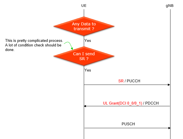
So the overall logic can be summarized as follows. First, UE has UL data or BSR pending. Second, UE does not have any suitable UL grant. Then SR becomes pending. After that, UE waits until a configured SR occasion comes. If all other conditions are OK, UE transmits positive SR on PUCCH. Then gNB may send UL Grant by DCI 0_0 or 0_1, and UE can transmit BSR and/or data on PUSCH.
Following illustration shows overal process for necessity based SR transmission with periodic SR opportunities configured by RRC.
Physical Channel to Carry SR
How UE send SR message ? UE send it on a PUCCH (or on UCI part on PUSCH). Not all PUCCH format can carry the SR. Some PUCCH format can carry SR and some other don't. UE is using a certain PUCCH format depending on situations to send SR. (For the detailed PUCCH format that can carry SR, refer to PUCCH format page).
In NR, PUCCH format 0 or 1 carrySR.
==> 38.213 - 9.2.4 states : A UE can be configured by SchedulingRequestResourceConfig a set of configurations for SR in a PUCCH transmission using either PUCCH format 0 or PUCCH format 1
Who is controlling the SR process ?
Even though SR message itself is a kind of physical layer message, it is controlled by MAC layer process (it is similar to many other physical layer channel are controlled by MAC layer)
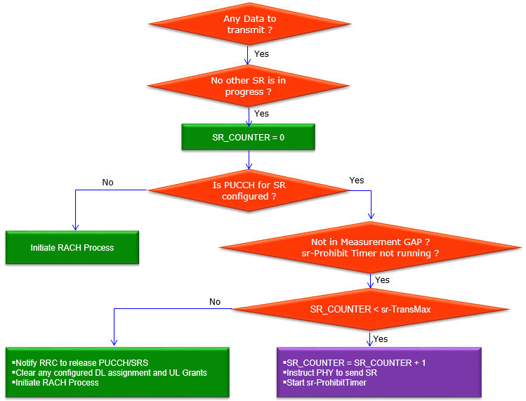
Overall SR process (when to send SR) is controlled by MAC layer as illustrated below. (See 38.321 5.4.4 for details)
When SR is not triggered/pre-empted ?
There are some cases where UE does not trigger SR even when it may trigger it otherwise. Followings are the list of those cases where UE does not send SR. These are all based on 38.321-5.4.4)
- UE already received UL Grant
- SR Opportunity falls into measurement gap period
- SR Prohitbit timer is running
- SR_COUNTER reaches the sr-TransMax
- PUCCH Resources for SR overlaps with the resources of PUSCH
- SR Occasion is in the same slot as PUSCH
// this is what I checked with a few experts, but I haven't found any explicit statement in 3GPP spec yet. It make sense to me that SR would not be transmitted in the same slot as PUSCH since UE already got the resource to transmit data, but not 100% sure in case of periodic SR. Is UE expected not to send SR at all ? or is still expected to send SR (at least Negative SR) ?
Positive SR vs Negative SR
This is one of the most confusing concept to me regarding 5G SR. At first, I thought negative SR means UE sends some kind of SR signal at every configured SR occasion when it has nothing to send. But this is not the right way to understand it. The clearer way to understand it is as follows.
In the simplest SR-only case, positive SR and negative SR are very different in terms of actual PHY transmission.
- Positive SR : UE transmits PUCCH on the configured SR resource. This means "I need UL grant".
- Negative SR : UE does not transmit SR on the configured SR resource. This means "I do not need UL grant".
So if there is a configured periodic SR occasion but UE has no pending SR, UE does not transmit a standalone PUCCH just to say "I have nothing to send". In this case, negative SR is more like a logical state, not an actual SR-only transmission.
Then why does the specification talk about negative SR ? The main reason is multiplexing with other UCI. If UE already needs to transmit PUCCH for HARQ-ACK or CSI in the same occasion, the SR state may be considered together with that PUCCH transmission. In that case, positive SR and negative SR can affect which PUCCH resource is used or what bits are appended to the UCI payload.
Putting it another way, the meaning can be summarized as follows.
- SR-only occasion + SR pending : positive SR. UE transmits SR on PUCCH.
- SR-only occasion + no SR pending : negative SR. UE normally transmits nothing for SR.
- HARQ/CSI PUCCH overlaps SR occasion + SR pending : positive SR is multiplexed or represented together with HARQ/CSI according to the PUCCH format and multiplexing rule.
- HARQ/CSI PUCCH overlaps SR occasion + no SR pending : negative SR is considered together with the HARQ/CSI PUCCH. UE still may transmit PUCCH, but that PUCCH is for HARQ/CSI, not for requesting UL grant.
As part of learning process, I will put down what is described in 3GPP specification and put my own questions. It will be appreciated if any of you let me learn via email or linkedIn.
38.213-9.2.4 UE procedure for reporting SR
The UE transmits a PUCCH in the PUCCH resource for the corresponding SR configuration only when the UE transmits a positive SR.
For a positive SR transmission using PUCCH format 0, the UE transmits the PUCCH by obtaining m_0 as described for HARQ-ACK information and by setting m_cs = 0. For a positive SR transmission using PUCCH format 1, the UE transmits the PUCCH as described in by setting b (0) = 0
38.213 - 9.2.5.1 UE procedure for multiplexing HARQ-ACK or CSI and SR in a PUCCH
If a UE would transmit a PUCCH with positive SR and at most two HARQ-ACK information bits in a resource using PUCCH format 0, the UE transmits the PUCCH in the resource using PUCCH format 0 in PRB(s) for HARQ-ACK information
If the UE would transmit negative SR and a PUCCH with at most two HARQ-ACK information bits in a resource using PUCCH format 0, the UE transmits the PUCCH in the resource using PUCCH format 0 for HARQ-ACK information
If a UE would transmit a PUCCH with O_ACK HARQ-ACK information bits in a resource using PUCCH format 2 or PUCCH format 3 or PUCCH format 4 in a slot, ceil[log2(K+1)] bits representing a negative or positive SR, in ascending order of the values of schedulingRequestResourceId and a schedulingRequestResourceId associated with schedulingRequestID-BFR-SCell,
If a UE would transmit a PUCCH with O_CSI report bits in a resource using PUCCH format 2 or PUCCH format 3 or PUCCH format 4 in a slot, ceil[log2(K+1)] bits representing a negative or positive SR, in ascending order of the values of schedulingRequestResourceId and a schedulingRequestResourceId associated with schedulingRequestID-BFR-SCell,
38,213 - 9 UE procedure for reporting control information :
If a UE would transmit on a serving cell a PUSCH without UL-SCH that overlaps with a PUCCH transmission on a serving cell that includes positive SR information, the UE does not transmit the PUSCH.
- Standalone SR resource : UE transmits PUCCH only for positive SR. If SR is negative, UE does not transmit a standalone SR PUCCH.
- PUCCH format 0 or 1 with HARQ-ACK : positive SR may change the PUCCH resource or sequence/cyclic shift behavior. Negative SR means UE does not request UL grant, but UE may still transmit PUCCH for HARQ-ACK.
- PUCCH format 2, 3 or 4 with HARQ-ACK/CSI : SR state can be represented by additional UCI bits. In this case, an all-zero SR field represents negative SR across the configured SRs.
- Most important point : negative SR does not mean UE sends a separate SR signal just to say "no data". It means "no positive SR request". It becomes visible only when it is multiplexed with another UCI transmission.
Another confusing point is whether there is any special PHY sequence for negative SR. My understanding is No. Negative SR itself does not have a special standalone sequence. For an SR-only occasion, negative SR means UE does not transmit SR PUCCH. For PUCCH format 0 or 1 multiplexed with HARQ-ACK, negative SR means the UE transmits the HARQ-ACK PUCCH without adding a positive SR request. For PUCCH format 2, 3 or 4 multiplexed with HARQ-ACK or CSI, the SR state is represented by ceil(log2(K+1)) UCI bits, and all-zero value represents negative SR across all K SRs. So negative SR is not a special sequence. It is either no SR transmission or an all-zero SR indication field when SR is multiplexed with other UCI.
: As mentioned above, I got much clearer understanding than before after chat with PHY/L1 Guru. I think the form of live dialog as quoted below would be better than I am trying to summarize it.
[Q] what would be the definition of negative SR ? 'No SR from UE' ? or 'SR from UE with bit field set to 0' ?
[A] it means "No SR". It is just that in NR, on certain PUCCH format and/or multiplexing rule, the UE sometimes send a SR bit if there is a SR occasion, even if UL Grant is not required
[Q] what do you mean by this "the UE sometimes send a SR bit if there is a SR occasion" ?
UE send SR with bit = 0 ?
[A] yes, but only when SR is not alone
[Q] 'only when SR is not alone' mean 'only the case where SR is scheduled together with other UCI' ?
[A] yes
[Q] What if a periodic SR is scheduled at slot N, No data to send from UE side. No other UCI is scheduled
at slot N... in this case UE should skip SR ? or send Negative SR ?
[A] The UE skips SR. 38.213 - 9.2.4 : The UE transmits a PUCCH in the PUCCH resource for the corresponding SR configuration only when the UE transmits a positive SR.
[Q] I see... but I got confused by other statements from 9.2.5.1
[A] 9.2.5.1 states what happens when you have collision with other resources
-> PUCCH Format 0 : a positive SR changes the cyclic shift values
-> PUCCH Format 1: put the HARQ in the SR resources for positive SR
-> Long PUCCH format: SR bits are appended to the payload
This is a nice chat with another expert, Xinya Shen. He kindly reached out to me to help me with the detailed understanding and allowed me to share this discussion with readers. I tried not to summarize anything and share the chat as it is so that you can have a kind of first hand experience with our chat and follow through the thread of chat (thought process) in real context.
[Xingya] In general, the SR resource is called Positive SR when the UE has a demand for SR transmission on the SR resource, and the SR resource is called Negative SR when the UE has no demand for SR transmission on the SR resource.
[Sharetechnote] Assuming this is periodic SR case, Does "the UE has no demand for SR transmission on the SR resource" mean that 'UE has no demand for SR transmission because it already has enough UL grant or no data to transmit' ?
[Xingya] Yes, your understanding is correct.
[38.213-9.2.4] The UE transmits a PUCCH in the PUCCH resource for the corresponding SR configuration only when the UE transmits a positive SR.
[Sharetechnote] Does this imply that UE does NOT transmit PUCCH when UE transmit a negative SR ? Does negative SR mean 'No PUCCH / NO SR' ?
[Xingya] This statement means that the UE transmits PUCCH on the SR resource ("PUCCH resource of the corresponding SR configuration") only if both PUCCH transmission and SR transmission are present.
When the UE does not need to transmit SR but only PUCCH, the UE transmits on the PUCCH resource, at this time, the SR resource is called negative SR
[38.213 - 9.2.5.1] If a UE would transmit a PUCCH with positive SR and at most two HARQ-ACK information bits in a resource using PUCCH format 0, the UE transmits the PUCCH in the resource using PUCCH format 0 in PRB(s) for HARQ-ACK information
If the UE would transmit negative SR and a PUCCH with at most two HARQ-ACK information bits in a resource using PUCCH format 0, the UE transmits the PUCCH in the resource using PUCCH format 0 for HARQ-ACK information
[Sharetechnote] What is the difference between the two statements ? It sounds same to me.
[Xingya] The difference between these two statements is the meaning of "resource". In the first statement, the "resource" refers to SR resource, while in the second statement, "resource" refers to PUCCH resource.
[Sharetechnote] Does this imply that SR can be transmitted via PUCCH format 2,3,4 as well as format 0,1 ? Is it going against the statement 'The UE transmits a PUCCH in the PUCCH resource for the corresponding SR configuration only when the UE transmits a positive SR.' from 38.213-9.2.4 ?
[Xingya] Yes. if the SR is transmitted via PUCCH fomat 2,3,4 it should be encoded with the ACK/NACK bits. For format 0, different m_cs value are used to distinguish the cases betwenn PUCCH with positive SR and PUCCH without SR. For PUCCH format 1, PUCCH with positive SR should be transmitted on SR resource.
[38.213 - 9] If a UE would transmit on a serving cell a PUSCH without UL-SCH that overlaps with a PUCCH transmission on a serving cell that includes positive SR information, the UE does not transmit the PUSCH.
[Sharetechnote] Does this imply that if aperiodic CSI report occasion and SR occasion overlaps, the aperiodic CSI report should drop ?
[Xingya] Yes
[Sharetechnote] Sometimes you use 'SR Resources' and 'PUCCH Resources' in different meaning which confuses me a little bit. Since SR is carried by PUCCH, I thought SR Resource is also a type of PUCCH Resource as in following statement The difference between these two statements is the meaning of "resource". In the first statement, the "resource" refers to SR resource, while in the second statement, "resource" refers to PUCCH resource.
When you say SR Resources, does it mean 'a type of PUCCH resource allocated for PUCCH' and when you say PUCCH resources, does it mean the PUCCH resource allocated only for Ack/Nack ?
[Xingya] Yes, your understanding is correct. The SR resource I mentioned refers to a type of PUCCH resource, configured by IE "Resource" in IE "SchedulingRequestResourceConfig", where IE "Resource" is associated to "PUCCH-ResourceId". The PUCCH resource is the resource that carry ACK/NACK.
SR Configurations
Followings are Configurations and Interdependancies among the parameters regarding SR (NOTE : You may need further understandings on pucch-Config. Refer to this note for pucch config details)
The important point is that SR configuration is not defined by a single IE. There is a logical SR configuration, there is an SR transmission resource configuration, and there is a PUCCH resource definition. These are connected by IDs.
- schedulingRequestId in SchedulingRequestToAddMod defines one logical SR configuration. This part defines MAC level parameters such as sr-ProhibitTimer and sr-TransMax.
- schedulingRequestResourceId in SchedulingRequestResourceConfig identifies one SR resource configuration. This is the configuration for a specific SR occasion/resource.
- schedulingRequestID in SchedulingRequestResourceConfig points back to the logical schedulingRequestId. This is the orange arrow in the diagram.
- periodicityAndOffset in SchedulingRequestResourceConfig defines when the SR occasion comes, for example every N slots/symbols with a certain offset.
- resource in SchedulingRequestResourceConfig points to a PUCCH-ResourceId in pucch-Config/resourceToAddModList. This is the green arrow in the diagram.
So the overall chain is as follows.
SchedulingRequestToAddMod.schedulingRequestId
--> SchedulingRequestResourceConfig.schedulingRequestID
--> SchedulingRequestResourceConfig.periodicityAndOffset and resource
--> pucch-Config.resourceToAddModList.PUCCH-ResourceId
In other words, schedulingRequestId tells which SR logical process this resource belongs to, and resource tells which actual PUCCH resource is used to transmit the SR.

Examples
The examples in this section show how SR configuration in RRC is related to the actual SR transmission in PHY log. The important chain is : logical SR configuration --> SR resource configuration --> PUCCH resource definition --> actual PUCCH carrying positive SR.
Example 1 : Positive SR transmitted on configured PUCCH format 1 resource
This example is based on the UE log. In this case, RRC configures one SR logical configuration with schedulingRequestId 0. Then RRC configures one SR transmission resource with schedulingRequestResourceId 1, links it back to schedulingRequestID 0, sets periodic SR occasions by periodicityAndOffset sl40: 8, and points it to PUCCH-ResourceId 12. Later, UE transmits a positive SR on that PUCCH resource.
The overall summary is as follows.
| Item | Value / Log | Meaning |
| Logical SR | schedulingRequestId 0 | Defines the SR process controlled by MAC. |
| SR resource | schedulingRequestResourceId 1, schedulingRequestID 0, periodicityAndOffset sl40:8, resource 12 | Maps SR process 0 to a periodic SR occasion and PUCCH resource 12. |
| PUCCH resource | PUCCH-ResourceId 12, format 1, PRB 50/0, CS 9, 14 symbols, OCC 2 | Defines the actual physical PUCCH resource used for SR. |
| PHY result | PUCCH: format=1 prb=50 prb2=0 symb=0:14 cs=9 occ=2 sr=1 | UE transmits positive SR on the configured PUCCH resource. |
| After SR | DCI 0_1 UL grant, then PUSCH | gNB provides UL grant and UE uses it to transmit UL data/BSR. |
The overall sequence is summarized as follows.
| Step | Layer / Channel | Log / Configuration | Meaning for SR |
| 1 | RRC / MAC config | schedulingRequestId 0, sr-TransMax n64 | Defines the logical SR process controlled by MAC. |
| 2 | RRC / PUCCH config | schedulingRequestResourceId 1, schedulingRequestID 0, periodicityAndOffset sl40:8, resource 12 | Maps SR process 0 to a periodic SR occasion and PUCCH resource 12. |
| 3 | RRC / PUCCH resource | PUCCH-ResourceId 12 = format 1, PRB 50/0, CS 9, OCC 2 | Defines the actual physical PUCCH resource used for SR. |
| 4 | PHY / PUCCH | PUCCH: format=1 prb=50 prb2=0 symb=0:14 cs=9 occ=2 sr=1 | UE transmits positive SR on the configured PUCCH resource. |
| 5 | PHY / PDCCH | PDCCH: dci=0_1 | gNB sends UL grant after receiving/handling SR. |
| 6 | MAC/PHY / PUSCH | MAC UL with SBSR, then PUSCH | UE uses the UL grant to transmit MAC data/BSR on PUSCH. |
The following part configures schedulingRequestId 0. This is the logical SR configuration used by MAC. In this log, sr-TransMax n64 is configured, meaning the maximum number of SR transmissions is n64.
mac-CellGroupConfig {
  schedulingRequestConfig {
    schedulingRequestToAddModList {
      {
        schedulingRequestId 0,
        sr-TransMax n64
      }
    }
  },
  bsr-Config {
    periodicBSR-Timer sf20,
    retxBSR-Timer sf320
  }
}
The logical channel configuration also refers to schedulingRequestID 0. This means this logical channel can use the SR logical configuration with ID 0 when it needs UL resource.
mac-LogicalChannelConfig {
  ul-SpecificParameters {
    priority 1,
    prioritisedBitRate infinity,
    bucketSizeDuration ms5,
    logicalChannelGroup 0,
    schedulingRequestID 0,
    logicalChannelSR-Mask FALSE,
    logicalChannelSR-DelayTimerApplied FALSE
  }
}
Yes, the PUCCH configuration is essential here. The SR resource does not define PRB/symbol/format by itself. It only has resource 12, and this value points to PUCCH-ResourceId 12 in the same pucch-Config. The following snippet shows both parts together : the actual PUCCH resource definition in resourceToAddModList and the SR mapping in schedulingRequestResourceToAddModList.
pucch-Config setup: {
  resourceToAddModList {
    ...
    {
      pucch-ResourceId 12,
      startingPRB 50,
      intraSlotFrequencyHopping enabled,
      secondHopPRB 0,
      format format1: {
        initialCyclicShift 9,
        nrofSymbols 14,
        startingSymbolIndex 0,
        timeDomainOCC 2
      }
    }
    ...
  },
  format1 setup: {
  },
  schedulingRequestResourceToAddModList {
    {
      schedulingRequestResourceId 1,
      schedulingRequestID 0,
      periodicityAndOffset sl40: 8,
      resource 12  // points to pucch-ResourceId 12 above
    }
  }
}
In this configuration, schedulingRequestResourceId 1 identifies the SR transmission resource. schedulingRequestID 0 links it back to the SR logical configuration in Step 1. periodicityAndOffset sl40: 8 defines the periodic SR occasions. resource 12 selects PUCCH-ResourceId 12, which is PUCCH format 1 using startingPRB 50, secondHopPRB 0, initialCyclicShift 9, nrofSymbols 14, startingSymbolIndex 0 and timeDomainOCC 2.
The following PHY line shows the actual SR transmission. The field sr=1 is the log indication for positive SR. The transmitted PUCCH matches PUCCH-ResourceId 12 configured above : format=1, prb=50, prb2=0, symb=0:14, cs=9 and occ=2.
20:10:28.613 [PHY] UL 0001 00 4628 100.8 PUCCH: format=1 prb=50 prb2=0 symb=0:14 cs=9 occ=2 sr=1 p=-40
After the positive SR, the gNB sends an uplink grant by DCI 0_1. Then UE transmits PUSCH. In this PUSCH, MAC includes SRB1 data and also a Short BSR. This is the expected next step after SR : SR asks for UL grant, and the grant enables UE to send UL MAC/RLC/PDCP data on PUSCH.
20:10:28.618 [PHY] DL 0001 00 4628  100.15 PDCCH: ss_id=2 cce_index=6 al=2 dci=0_1 k2=4
        rb_alloc=0x4b3
        time_domain_rsc=1
        mcs=0
        harq_process=0
        tpc_command=1
        ul_sch_indicator=1
20:10:28.618 [MAC] UL 0001 00 LCID:1 len=36 SBSR:lcg=0 bs=0 SE PHR:ph=63 pc=40 PAD:len=89
        Short BSR:
          LCG ID: 0 Buffer Size: 0 (0)
20:10:28.618 [PHY] UL 0001 00 4628  100.19 PUSCH: harq=0 prb=20:29 symb=0:14 CW0: tb_len=133 mod=2 rv_idx=0 cr=0.12 retx=0 p=-40
Example 2 : Negative SR case
This is an illustrative example using the same SR configuration as Example 1. The point of this example is a little tricky because negative SR does not usually appear as a standalone PHY transmission. If the SR occasion comes but UE has no pending SR, UE normally does not transmit an SR-only PUCCH. So for a standalone negative SR, what we should look for in the log is not a special sr=0 line. We should expect that there is no PUCCH ... sr=1 transmission at that SR occasion.
The same configuration from Example 1 is assumed here.
The overall summary is as follows.
| Case | UE behavior | How to read it in log |
| Standalone positive SR | UE transmits PUCCH with sr=1. | A PUCCH line with sr=1 appears on the configured SR resource. |
| Standalone negative SR | UE does not transmit SR-only PUCCH. | No special sr=0 line is expected. We just do not see PUCCH ... sr=1 at that SR occasion. |
| Negative SR with HARQ/CSI | UE may still transmit PUCCH, but for HARQ/CSI, not for SR request. | PUCCH may appear with HARQ/CSI information, but without positive SR indication. |
| Format 2/3/4 multiplexing | SR state can be represented by UCI bits. | All-zero SR indication bits represent negative SR across configured SRs. |
The overall sequence for a standalone negative SR case can be summarized as follows.
| Step | Condition / Event | Expected UE behavior | What we expect in log |
| 1 | RRC configures SR occasion by periodicityAndOffset sl40:8 and resource 12. | UE knows where/when SR can be transmitted. | RRC shows SchedulingRequestResourceConfig and PUCCH-ResourceId 12. |
| 2 | No UL data or BSR is pending, or UE already has a proper UL grant. | SR is not pending. | No MAC indication that SR is triggered. |
| 3 | The configured SR occasion arrives. | UE does not transmit standalone SR PUCCH. | No PUCCH line with sr=1 on resource 12. |
| 4 | Since there is no positive SR request. | gNB does not need to send an UL grant because of SR. | No SR-triggered DCI 0_0/0_1 is expected. |
pucch-Config setup: {
  resourceToAddModList {
    ...
    {
      pucch-ResourceId 12,
      startingPRB 50,
      intraSlotFrequencyHopping enabled,
      secondHopPRB 0,
      format format1: {
        initialCyclicShift 9,
        nrofSymbols 14,
        startingSymbolIndex 0,
        timeDomainOCC 2
      }
    }
    ...
  },
  schedulingRequestResourceToAddModList {
    {
      schedulingRequestResourceId 1,
      schedulingRequestID 0,
      periodicityAndOffset sl40: 8,
      resource 12
    }
  }
}
For this case, the log does not show a special negative SR sequence. The expected log is basically the absence of a positive SR PUCCH at the SR occasion. In other words, we should not expect a line like this.
// This line is NOT expected for standalone negative SR
// [PHY] UL ... PUCCH: format=1 prb=50 prb2=0 symb=0:14 cs=9 occ=2 sr=1 p=...
So in this case, negative SR means no positive SR transmission. It is not a separate PUCCH signal with a special negative SR sequence.
Negative SR becomes visible only when SR state is considered together with another UCI transmission, for example HARQ-ACK or CSI. In that case, UE may still transmit PUCCH, but the PUCCH is transmitted for HARQ-ACK/CSI. The SR part means "no positive SR request".
// Imaginary HARQ-ACK PUCCH overlapping an SR occasion, but SR is not pending
[PHY] UL ... PUCCH: format=1 prb=50 prb2=0 symb=0:14 cs=1 occ=0 ack=1 p=-40
// No sr=1 is shown. The PUCCH is for HARQ-ACK, not for positive SR.
For PUCCH format 2, 3 or 4, the SR state can be represented by additional UCI bits. In that case, an all-zero SR indication field represents negative SR across all configured SRs considered in that slot.
// Imaginary long PUCCH case
O_ACK = HARQ-ACK bits
K = number of SRs considered in the slot
SR indication bits = ceil(log2(K+1))

SR indication bits = all zero  // negative SR across all K SRs
O_UCI = O_ACK + ceil(log2(K+1))
Example 3 : Negative SR considered together with HARQ/CSI PUCCH
This is an illustrative example for the case where HARQ/CSI PUCCH overlaps with an SR occasion, but UE has no pending SR. In this case, UE may still transmit PUCCH because HARQ-ACK or CSI has to be transmitted. But this PUCCH is not a positive SR request. From SR point of view, it is a negative SR case.
The overall summary is as follows.
| Item | Condition / Value | Meaning |
| SR occasion | Configured periodic SR resource exists. | UE has an opportunity to send SR in this slot. |
| SR state | No SR is pending. | SR is negative. UE is not requesting UL grant. |
| Other UCI | HARQ-ACK or CSI needs to be transmitted in the same slot. | UE may still transmit PUCCH because of HARQ/CSI. |
| Format 0/1 behavior | HARQ-ACK PUCCH is transmitted without positive SR indication. | PUCCH is for HARQ-ACK, not for SR request. |
| Format 2/3/4 behavior | SR indication bits are all zero. | All-zero SR indication represents negative SR. |
The overall sequence is summarized as follows.
| Step | Condition / Event | Expected UE behavior | Meaning |
| 1 | SR occasion comes from SchedulingRequestResourceConfig. | UE checks whether SR is pending. | SR opportunity exists, but this alone does not force transmission. |
| 2 | No UL data/BSR pending, or UE already has a proper UL grant. | SR state is negative. | UE does not request UL grant. |
| 3 | HARQ-ACK or CSI is scheduled in the same slot. | UE still transmits PUCCH for HARQ-ACK/CSI. | PUCCH exists, but not because of positive SR. |
| 4 | SR state is multiplexed/considered with that PUCCH. | Negative SR is represented by no positive SR indication, or by all-zero SR indication bits for long PUCCH. | Negative SR means no UL grant request. |
For PUCCH format 0 or 1, if HARQ-ACK is transmitted and SR is negative, UE transmits the PUCCH for HARQ-ACK. There is no separate negative SR sequence. In many logs, you would just see HARQ-ACK PUCCH without sr=1.
// Imaginary example : HARQ-ACK PUCCH overlaps SR occasion, but SR is not pending
[PHY] UL ... PUCCH: format=1 prb=50 prb2=0 symb=0:14 cs=1 occ=0 ack=1 p=-40

// Interpretation
// - PUCCH is transmitted because HARQ-ACK is required.
// - No sr=1 is shown, so this is not a positive SR request.
// - From SR point of view, this corresponds to negative SR.
For PUCCH format 2, 3 or 4, SR state can be represented by additional UCI bits when SR is multiplexed with HARQ-ACK or CSI. If there are K SRs considered in the slot, the SR indication field has ceil(log2(K+1)) bits. An all-zero value represents negative SR across all K SRs.
// Imaginary example : long PUCCH with CSI and negative SR
O_CSI = 7 bits
K = 1 SR considered in this slot
SR indication bits = ceil(log2(1+1)) = 1 bit

SR indication bit = 0  // negative SR
O_UCI = O_CSI + 1 = 8 bits

[PHY] UL ... PUCCH: format=4 prb=49 prb2=1 symb=0:14 occ=0 csi=0xxxxxxx p=-40

// Interpretation
// - PUCCH is transmitted because CSI is required.
// - The SR indication bit is 0, meaning negative SR.
// - UE is not asking for UL grant.
RRC Parameters
Everything in the SR procedure above runs on values that arrive over RRC, and this section is where those values are defined. Three IEs carry them. SchedulingRequestConfig says how many SR configurations exist and how each one behaves when the network does not answer. SchedulingRequestResourceConfig says where and when the UE may send one. LogicalChannelConfig says which logical channel is allowed to trigger which SR. Read the three as a chain rather than as three lists, because each one points at the next by identifier.
SchedulingRequestConfig : how many SR configurations, and how persistent each one is
Look again at the flowchart under Who is controlling the SR process ? Two of its decision boxes take their values from here. The first is sr-ProhibitTimer, the timer the UE checks before it sends again. The second is sr-TransMax, the ceiling that sends the UE to RACH instead of to another SR.
Following is based on
SchedulingRequestConfig ::=         SEQUENCE {
    schedulingRequestToAddModList       SEQUENCE (SIZE (1..maxNrofSR-ConfigPerCellGroup)) OF SchedulingRequestToAddMod
                                                                                                          OPTIONAL, -- Need N
    schedulingRequestToReleaseList      SEQUENCE (SIZE (1..maxNrofSR-ConfigPerCellGroup)) OF SchedulingRequestId
                                                                                                          OPTIONAL  -- Need N
}

SchedulingRequestToAddMod ::=       SEQUENCE {
    schedulingRequestId                 SchedulingRequestId,
    sr-ProhibitTimer                    ENUMERATED {ms1, ms2, ms4, ms8, ms16, ms32, ms64, ms128}          OPTIONAL, -- Need S
    sr-TransMax                         ENUMERATED { n4, n8, n16, n32, n64, spare3, spare2, spare1}
}

SchedulingRequestConfig-v1700 ::=       SEQUENCE {
    schedulingRequestToAddModListExt-v1700  SEQUENCE (SIZE (1..maxNrofSR-ConfigPerCellGroup)) OF SchedulingRequestToAddModExt-v1700
                                                                                                          OPTIONAL  -- Need N
}

SchedulingRequestToAddModExt-v1700 ::=  SEQUENCE {
    sr-ProhibitTimer-v1700                  ENUMERATED { ms192, ms256, ms320, ms384, ms448, ms512, ms576, ms640, ms1082, spare7, spare6, spare5, spare4, spare3, spare2, spare1}
                                                                                                          OPTIONAL  -- Need R
}

SchedulingRequestId ::=             INTEGER (0..7)

maxNrofSR-ConfigPerCellGroup            INTEGER ::= 8       -- Maximum number of SR configurations per cell group
Release 17 added a second prohibit timer, and the way the two interact is worth knowing. The new field, sr-ProhibitTimer-v1700, sits in a parallel list called schedulingRequestToAddModListExt-v1700. That list carries the same number of entries as the original one, and keeps them in the same order. Its values run from ms192 up to ms1082, well beyond the ms128 ceiling of the original field. When the network configures it, the UE ignores sr-ProhibitTimer without the suffix. When neither field is configured, the UE applies the value 0. That default is easy to miss, and it explains why an SR configuration with no prohibit timer transmits at every occasion until a grant arrives or sr-TransMax is reached.
The two identifier limits are worth reading together. SchedulingRequestId is INTEGER (0..7), and maxNrofSR-ConfigPerCellGroup is 8. So a cell group carries at most eight SR configurations, and the identifier space is exactly full. No spare value is left over to mean "none", which is why LogicalChannelConfig marks its schedulingRequestID as OPTIONAL instead.
SchedulingRequestResourceConfig : where and when the SR is actually sent
An SR configuration on its own cannot be transmitted. It needs an occasion in time and a PUCCH resource to carry it, and that is what this IE supplies. Note which way the pointer runs here. The resource names the configuration through schedulingRequestID, rather than the configuration listing its own resources.
Following is based on
SchedulingRequestResourceConfig ::=     SEQUENCE {
    schedulingRequestResourceId             SchedulingRequestResourceId,
    schedulingRequestID                     SchedulingRequestId,
    periodicityAndOffset                    CHOICE {
        sym2                                    NULL,
        sym6or7                                 NULL,
        sl1                                     NULL,                       -- Recurs in every slot
        sl2                                     INTEGER (0..1),
        sl4                                     INTEGER (0..3),
        sl5                                     INTEGER (0..4),
        sl8                                     INTEGER (0..7),
        sl10                                    INTEGER (0..9),
        sl16                                    INTEGER (0..15),
        sl20                                    INTEGER (0..19),
        sl40                                    INTEGER (0..39),
        sl80                                    INTEGER (0..79),
        sl160                                   INTEGER (0..159),
        sl320                                   INTEGER (0..319),
        sl640                                   INTEGER (0..639)
    }                                                                                                       OPTIONAL,   -- Need M
    resource                                PUCCH-ResourceId                                                OPTIONAL    -- Need M
}

SchedulingRequestResourceConfigExt-v1610 ::=   SEQUENCE {
    phy-PriorityIndex-r16                       ENUMERATED {p0, p1}                                         OPTIONAL,   -- Need M
    ...
}

SchedulingRequestResourceConfigExt-v1700 ::=    SEQUENCE {
    periodicityAndOffset-r17                        CHOICE {
        sl1280                                          INTEGER (0..1279),
        sl2560                                          INTEGER (0..2559),
        sl5120                                          INTEGER (0..5119)
    }                                                                                                       OPTIONAL   -- Need M
}

SchedulingRequestResourceConfigExt-v1900 ::=    SEQUENCE {
    symbolType-r19                                  ENUMERATED {sbfd, non-sbfd}                             OPTIONAL   -- Need R
}

SchedulingRequestResourceId ::=     INTEGER (1..maxNrofSR-Resources)

maxNrofSR-Resources                     INTEGER ::= 8       -- Maximum number of SR resources per BWP in a cell.
SCS = 15 kHz: 2sym, 7sym, 1sl, 2sl, 4sl, 5sl, 8sl, 10sl, 16sl, 20sl, 40sl, 80sl
SCS = 30 kHz: 2sym, 7sym, 1sl, 2sl, 4sl, 5sl, 8sl, 10sl, 16sl, 20sl, 40sl, 80sl, 160sl
SCS = 60 kHz: 2sym, 7sym/6sym, 1sl, 2sl, 4sl, 8sl, 16sl, 20sl, 40sl, 80sl, 160sl, 320sl
SCS = 120 kHz: 2sym, 7sym, 1sl, 2sl, 4sl, 5sl, 8sl, 10sl, 16sl, 40sl, 80sl, 160sl, 320sl, 640sl
SCS = 480 kHz: 1sl, 2sl, 4sl, 8sl, 16sl, 40sl, 80sl, 160sl, 320sl, 640sl, 1280sl, 2560sl
SCS = 960 kHz: 1sl, 2sl, 4sl, 8sl, 16sl, 40sl, 80sl, 160sl, 320sl, 640sl, 1280sl, 2560sl, 5120sl
sym6or7 corresponds to 6 symbols if extended cyclic prefix and a SCS of 60 kHz are configured, otherwise it corresponds to 7 symbols.
For periodicities 2sym, 7sym and sl1 the UE assumes an offset of 0 slots.
If periodicityAndOffset-r17 is present, any previously configured periodicityAndOffset (without suffix) is released, and vice versa.
UE indicates support of the following SR periodicities in additionalSR-Periodicities (see TS 38.306, clause 4.2.6): SCS = 30 kHz: 5sl. SCS = 120 kHz: 5sl, 10sl.
(38.213-9.2.4) The UE can be provided, by phy-PriorityIndex in SchedulingRequestResourceConfig, a priority index 0 or a priority index 1 for the SR. If the UE is not provided a priority index for SR, the priority index is 0.
Two extensions widen what a single SR resource can be. The first is periodicityAndOffset-r17, which adds sl1280, sl2560 and sl5120. Those are far longer than anything the original CHOICE offers. Such long periods belong to the 480 kHz and 960 kHz subcarrier spacings, where a slot is very short and a useful SR period needs a great many of them. The two versions are exclusive. Configuring periodicityAndOffset-r17 releases any periodicityAndOffset without the suffix, and the reverse holds as well.
Release 19 added symbolType, and it belongs to subband full duplex operation. The network sets it when SR transmissions on this UL BWP are restricted to SBFD symbols only, or to non-SBFD symbols only. It leaves the field out when the SR may land in either kind of symbol in different slots of the same BWP.
LogicalChannelConfig : which logical channel is allowed to trigger which SR
Nothing so far has said which data actually triggers an SR. That link is made per logical channel, and it is made in this IE. The same IE carries the mask and the delay timer flag that can stop a logical channel from triggering one, which is why a UE that has data can still stay silent.
Following is based on
LogicalChannelConfig ::=            SEQUENCE {
    ul-SpecificParameters               SEQUENCE {
        priority                            INTEGER (1..16),
        prioritisedBitRate                  ENUMERATED {kBps0, kBps8, kBps16, kBps32, kBps64, kBps128, kBps256, kBps512,
                                            kBps1024, kBps2048, kBps4096, kBps8192, kBps16384, kBps32768, kBps65536, infinity},
        bucketSizeDuration                  ENUMERATED {ms5, ms10, ms20, ms50, ms100, ms150, ms300, ms500, ms1000,
                                                            spare7, spare6, spare5, spare4, spare3,spare2, spare1},
        allowedServingCells                 SEQUENCE (SIZE (1..maxNrofServingCells-1)) OF ServCellIndex
                                                                                                            OPTIONAL,   -- Cond PDCP-CADuplication
        allowedSCS-List                     SEQUENCE (SIZE (1..maxSCSs)) OF SubcarrierSpacing                   OPTIONAL,   -- Need R
        maxPUSCH-Duration                   ENUMERATED {ms0p02, ms0p04, ms0p0625, ms0p125, ms0p25, ms0p5, ms0p01-v1700, spare1}
                                                                                                                OPTIONAL,   -- Need R
        configuredGrantType1Allowed         ENUMERATED {true}                                                   OPTIONAL,   -- Need R
        logicalChannelGroup                 INTEGER (0..maxLCG-ID)                                              OPTIONAL,   -- Need R
        schedulingRequestID                 SchedulingRequestId                                                 OPTIONAL,   -- Need R
        logicalChannelSR-Mask               BOOLEAN,
        logicalChannelSR-DelayTimerApplied  BOOLEAN,
        ...,
        bitRateQueryProhibitTimer       ENUMERATED {s0, s0dot4, s0dot8, s1dot6, s3, s6, s12, s30}               OPTIONAL,    -- Need R
        [[
        allowedCG-List-r16                  SEQUENCE (SIZE (0.. maxNrofConfiguredGrantConfigMAC-1-r16)) OF ConfiguredGrantConfigIndexMAC-r16
                                                                                                                OPTIONAL,   -- Need S
        allowedPHY-PriorityIndex-r16        ENUMERATED {p0, p1}                                                 OPTIONAL    -- Need S
        ]],
        [[
        logicalChannelGroupIAB-Ext-r17      INTEGER (0..maxLCG-ID-IAB-r17)                                      OPTIONAL,   -- Need R
        allowedHARQ-mode-r17                ENUMERATED {harqModeA, harqModeB}                                   OPTIONAL    -- Need R
        ]],
        [[
        enhancedLCP-r19                 SEQUENCE{
            priorityAdjustmentThreshold-r19 INTEGER (1..64),
            additionalPriority-r19          INTEGER (1..16),
            ...
        }                                                                                                       OPTIONAL    -- Need R
        ]]
    }                                                                                                       OPTIONAL,   -- Cond UL
    ...,
    [[
    channelAccessPriority-r16           INTEGER (1..4)                                                      OPTIONAL,   -- Need R
    bitRateMultiplier-r16               ENUMERATED {x40, x70, x100, x200}                                   OPTIONAL    -- Need R
    ]]
}
schedulingRequestID inside ul-SpecificParameters is the link back to SchedulingRequestConfig. When it is present, it names the SR configuration that applies to this logical channel. When it is absent, the logical channel has no SR configuration of its own, so data arriving on it cannot start the SR procedure described earlier.
Two Release 16 restrictions sit alongside it, and both matter when a logical channel has to be kept off certain grants. The field allowedCG-List names the configured grant configurations this logical channel may use, and a zero length sequence means it may use none of them. That field is ignored while an SDT procedure is running. Its partner allowedPHY-PriorityIndex does the same job for dynamic grants, matching on the PHY priority index carried in the grant. If the grant carries no such index, the logical channel maps to it only when the field is set to p0.
Release 19 added enhancedLCP, which lets a logical channel raise its own priority under a deadline. Inside it, priorityAdjustmentThreshold is a remaining time threshold in milliseconds, and additionalPriority is the value that replaces the configured priority once that threshold is met. The specification requires additionalPriority to be smaller than priority. A smaller number means a higher priority in MAC, so the adjustment can only make the channel more important, never less.
The three IEs form a chain, and every link is an identifier : LogicalChannelConfig names a SchedulingRequestId, SchedulingRequestResourceConfig names the same SchedulingRequestId, and it names a PUCCH-ResourceId in turn. The diagram under SR Configurations draws exactly those two hops.An absent prohibit timer is not an absent restriction, it is zero : with neither field configured, the UE applies 0. It may then transmit at every SR occasion until sr-TransMax stops it.The Release 17 prohibit timer replaces the original rather than extending it : when sr-ProhibitTimer-v1700 is configured, the UE ignores sr-ProhibitTimer without the suffix. The two lists run in parallel and are equally long.Eight is the limit in both directions : maxNrofSR-ConfigPerCellGroup is 8 and maxNrofSR-Resources is 8. SchedulingRequestId counts from 0 and SchedulingRequestResourceId counts from 1, which is a common source of off-by-one confusion when reading a log.A logical channel with no schedulingRequestID cannot trigger SR at all : the field is optional. Leaving it out is how the network stops a logical channel from asking for a grant.
Reference
- NR/5G-PUSCH&SR Conflict
- 5G-NR: UPLINK RESOURCE REQUEST
- 3GPP TS 38.331 V19.3.0, Radio Resource Control (RRC) protocol specification.