When I first studying on 5G Beam Management based on 3GPP, the image in my mind (whether it is correct or not) was that the beam management is mostly about Network activity, it is mostly passive in UE's perspective except the initial beam selection. My image was something like this
i) Network informs the UE of the detailed information about all the beams it uses based on all the possible codebooks defined in 3GPP.
ii) UE performs the measurement for each of the beam and send the report to NW.
iii) Network explicitely direct UE to use a specific beam based on the measurement report.
In this scenario, UE just have passive roles.. that is just perform the measurement and send it to network and tune its beam as directed by Network. But in reality (at least up to now, Mar 2022) I don't think this kind of fully network guided / closed loop type of beamforming happens at the full maturity. In most case (especially for FR2 where beam management is expected to play a crucial role), Network just provides UE with some guidence of the beam selection/change with relatively long interval (like every 20ms interval or longer) and UE should play active roles to adjust its own Rx beam at every slot to maintain the best radio link to network beam (TRP).
In this note, I will try to explain how those active roles on UE side happens. Actually the algorithms and implementation is mainly up to each modem protocol stack implementation (not explicitely defined in 3GPP) and I am not supposed to mention about any specific implementation. I will just to try explain overall (generic) way of UE side beam management based on those materials available in public domain (check out the reference section).
- Antenna Modules on the Phone
- How do the multiple antenna work ?
- What do we have to know of the Antenna Characteristics ?
- Testing in the Lab
- Snapshot of RRM Test
Antenna Modules on the Phone
For mmWave, most of UE (actually all of the UE as far as I know of) has multiple antenna module on the device (The exact number of antenna modules on the device is up to UE manufacturer. As far as I have observed, the minimum number was two and the max number is 4).
Why multiple antenna ? As you know, it is not feasible to transmit the signal in omni direction from TRP (gNB transmittion antenna). It will transmit the signal in the form of beam (i.e, radiation in a certain restricted range of angles in spherical cordinate) and the direction and angular width of the beam varies very quickly depending on situation. In order to receive those varying beam in any condition, ideally the Rx antenna (UE antenna) should be omni directional, but implmenting omni antenna at mmWave on UE side is also not feasible. As an alternative, you may implement one big antenna array with wide range of weighting factors (codebook) that can cover very wide range. This may be possible but inefficient because user may change the angular position of UE often and even more seriously the antenna module can be blocked by user's hand or any other obstacle. If UE has only one antenna module, the connection would drop if that one antenna is blocked. Therefore, the most widely adopted solution is to put multiple antenna module on the UE and select the best module at a specific moment (e,g, at a specific slot).
I think following placement of antenna module was the first generation of mmWave UE antenna (likely to be suggested by Modem manufacturer).
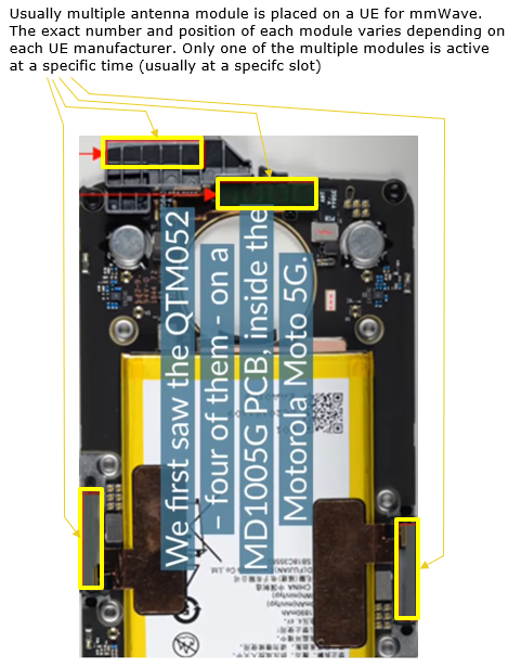
Source : Qualcomm QTM052 mmWave Antenna Module Analysis (YouTube)
For more specific information about Antenna placement and some characteristics open to public space, you may search in FCC document. As far as I observed, SamSung is most open for sharing the details in FCC document. I haven't seen any other manufacturer sharing as detailed information as SamSung. Following is one example.
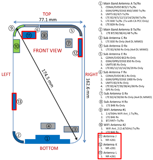
Source : FCC ID: A3LSMG977U (SamSung) - Test Setup Photos
For the details of characterizations of each antenna modules and beam ID of the SamSung device shown above is described in details in this FCC document : Power Density Simulation Report - FCC ID : A3LSMG977U
How do the multiple antenna work ?
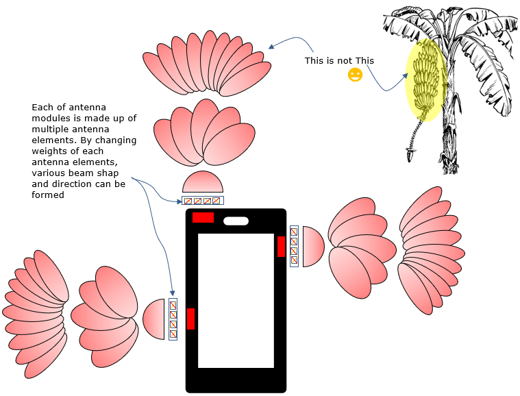
Usually each of the antenna modules on UE is an array antenna made up of multiple antenna elements (As far as I know, all the antenna module on current UE is 1D array antenna(Uniform Linear Array) and I haven't seen 2D array(Uniform Rectangular Array) as of yet). By changing the weighting factor for each antenna elements in a module (the set of weighting factors are called Codebook), each module can form beams with various direction and width as depicted below.
At a specific moment of reception (at specific slots receiving DL signal), only one specific beam on a specific module gets active. So the big.. big... big... question is how UE can figure out the best module and best beam at each and every specific slot. This is completely upto modem algorithm and nothing to be shared in public. But you may get some general idea from various papers as explained in next section.
a codeword is a set of analog phase shift values, or a set of magnitude plus phase shift values, applied to the antenna elements, in order to form an analog beam
You may get some intuitive understanding on this mechanism acting in live can be seen in the YouTube video as linked below. You would get much better understanding just by watching this single video than reading my notes 10 times (a picture is worth of a thousand words :)

Source : 5G Mobile mmWave OTA Test Network (YouTube)
Optional Reading : This is direct quote from this paper : Beam Codebook Design for 5G mmWave Terminals. You may skip this if you are not specifically interested in this area or you think this is too much reading. This part is not essential to get the idea of this note. this is more for my person reading for future reference.
- Antenna for mmWave bands is intrinsically directional. For example, the patch antenna usually has a high front-toback ratio and consequently can cover at most half-sphere. The directional element radiation pattern will also result in the drift of the peak gain direction from the intended one if the beamforming vector is merely designed based on the steering vector. In addition, when placed inside mobile handsets, the radiation gain of the mmWave antenna is less than the free-space case due to blockage loss and the radiation pattern shape is also changed.
- Antenna placement and antenna spacing may not be regular. For example, the planar array may not have the halfwavelength spacing between adjacent elements due to formfactor constraints. Another reason is related to the multifrequency bands that the mmWave terminal has to support.
- The mmWave bands for 5G deployment in US will include 24 GHz, 28 GHz and 39 GHz, etc1. The same antenna arrays, however, are likely to be used at all these carrier frequency bands. Therefore, a half-wavelength spacing at a frequency band will result in less than (or more than) half-wavelength spacing at other lower (or higher) frequency bands.
- A 5G mmWave capable UE is typically equipped with multiple antenna arrays. For example, there are at most four mmWave modules mounted on the top, bottom, left and right edges of the phone, respectively. Multiple mmWave antenna arrays are necessary to enable a good spherical coverage over the whole sphere and to circumvent human body blocking. In a benchmark codebook design, the beam codewords are designed independently for each array, which is a suboptimal solution since the interaction and coordination between the arrays are ignored.
What do we have to know of the Antenna Characteristics ?
According to Beam Codebook Design for 5G mmWave Terminals, the factors affecting the codebook design can be listed as follows
- 1) Antenna element type and gain (e.g. isotropic, dipole, microstrip patch);
- 2) Array layout (e.g. linear, rectangular, circular, cylinder) and placement if there are multiple arrays;
- 3) Requirements of codebook (e.g. codebook size, required coverage regions, phase shifter resolution);
- 4) Consideration about UE housing (e.g., display screen, battery);
- 5) The coordination among different arrays mounted on the same terminal.
If you take all of these into consideration, you would have almost infinite permutations of factors which is impossible to implement. Even with much restricted set of factors assuming linear microstrip patch with 4 antenna elements within a module (L = 4), 2 bit resolution of phase shifter (b = 2) and codebook size = 4 (K=4), the exhastive search space for finding optimal codebook is 2^(b L K) = 2^(2*4*4) = 2^32 which is not feasible to implement. So modem manufacturer needs to come out with some special procedure to find much smaller set of permutations which are closer to optimal solution.
Once you identify codebook, you may visualize the performance of each codeword as shown below to communicate about the characteristics of each beam created by each codeword. Only one of the beam is active at a specific Tx and Rx timing (usually in a slot). You may notice that each of the beam is pretty directional which covers only a small area in spherical coordinates and you need to consider the coverage of each beam when you are testing the UE performance in mmWave.

Source : Beam Codebook Design for 5G mmWave Terminals
Eventually what you need to get is heat map (e.g, heat map for Tx power, Rx power, Sensitivity etc) for every codebook elements, antenna module and the composite of all the codebook elements for varous scenario.
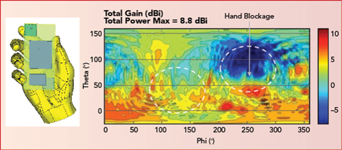
Source : First 5G mmWave Antenna Module for Smartphones
Testing in the Lab
Practically I think it is almost impossible to duplicate in the lab live-network environment for beam management, but still you may do a lot of testing for mmWave in the lab. I don't think you can easily perform such a test in the lab for fast sweeping beam or differetiation between Narrow beam and Widebeam and differentiation between with QCL and without QCL etc in the lab environment, but you can still perform many kinds of static / semi-static beam and just chaning power and direction of the beam among only a few different directions.
First thing you need to do for lab testing is to find the proper chamber for the test. There are roughly three types of chambers availble in the market. Whitebox/line of sight Chamber, CATR Chamber and MPAC chamber. Ideally it would be the best to use MPAC to create an environment and beam variation close to live network, but there would be many technicall challenges to properly operate the chamber and cost issues as well. By the time you may need MPAC chamber, most people would take the device out in the field and do test in live. I think most common type of chamber being used in the lab is whitebox type of chamber as illustrated below.

If your situation allows, you may have more versatile chamber as shown below and perform more diverse and realistic beam management test.
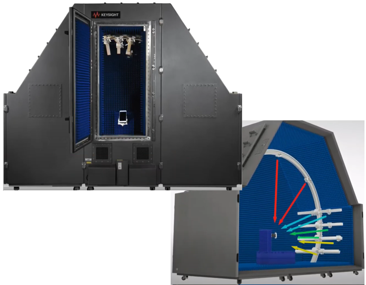
Source : Edited from Introducing Keysights F9660A 3D MPAC OTA Chamber
Once you got a chamber, you may perform various steps of test as listed below. Each of the test in the list would take a lot of time and effort until you reach a certain maturity level.
- 1) Basic connection establishment : with very basic RRC configuration (no ptrs, no trs, no csi report) and with low throughput. Just check how reliably a UE attaches NR cell. At this step, you may need to do a lot of trial and errors with angular position of UE with respect to gNB horn antenna. If you have the information about exact the position of each antenna module on UE and heat map, it will greatly help.
- 2) Max throughput Test with the basic RRC configuration (no ptrs, no trs, no csi report)
- 3) Max throughput test with PTRS : Does PTRS help to achieve and maintain high throughput ?
- 4) Connection establishment test with simple CSI (single set of trs) : Does UE accept the configuration and does it help for stable connection ?
- 5) Connection establishement test with single set of TRS and CSI report with multi port (e.g, p2, p4) : Does UE accept the configuration and does it help for stable connection ?
- 7) Connection establishment test with TRS, CSI Report and QCL between SSB and CSI beam : : Does UE accept the configuration and does it help for stable connection ?
- 8) Max throughput test with configuration 7) : Does it help to achieve and maintain high throughput ?
- 9) Changing the angular position of UE and check the throughput performance or heatmap variation. (You can change the UE's angular position in positioner in the chamber)
- 10) Perform more complicated Beam Management test like RRM test (You would need more versatile chamber like MPAC chamber for this type of test)
Snapshot of RRM Test
For a few years at early phase of 5G, Beam Related testing was mostly planned and performed by research and creativity of modem manufacturer, UE manufacturer and network infra vendor because there was no common specification for the test. In those period, everybody have done a little bit different set of tests. So passing the tests in one party (modem vendor or UE vendor or live network) does not guarantee working in other party. In those days, live network configuration played the role of ultimate reference, but in many cases it is hard to duplicate the live network configuration with lab test equipment and even those live network configuration varies widely depending on vendors and network operators.
Now (as of Mar 2022) I see 3GPP RRM Test Specification (38.533) is pretty mature. Even though it seems much simpler than live network situation, at least now we have some common RRC configuration and Beam Setup that is expected to pass with every UE.
What I am trying to do in this section is to put some key parameters and procedures based on FR2 RRM test. I am not trying to duplicate RRM specification as it is. I will just try to put some big picture of those RRM test with the reference to the original document so that you can find the corresponding specification more easily.
SSB for FR2 CSC 120
This is based on 38.533-Table A.3.2-1: SSB allocation for FR2
|
SSB Parameters |
Values |
|||
|
Pattern |
SSB1 FR2 |
SSB3 FR2 |
SSB5 FR2 |
SSB7 FR2 |
|
Channel BW (Mhz) |
100 |
100 |
100 |
100 |
|
SSB Periodicity (ms) |
20 |
20 |
20 |
20 |
|
SSB Bitmap |
11000000 00000000 00000000 00000000 00000000 00000000 00000000 00000000 |
10000000 00000000 00000000 00000000 00000000 00000000 00000000 00000000 |
00110000 00000000 00000000 00000000 00000000 00000000 00000000 00000000 |
01000000 00000000 00000000 00000000 00000000 00000000 00000000 00000000 |
|
SSB Position in Frequency Domain |
Any allowed SGSN |
Any allowed SGSN |
Any allowed SGSN |
Any allowed SGSN |
RACH Configuration for FR2
|
Field |
Value |
Comment |
|||
|
PRACH Configuration |
PRACH 1 FR2 |
PRACH 2 FR2 |
PRACH 3 FR2 |
PRACH 4 FR2 |
|
|
prach-ConfigurationIndex |
190 |
190 |
190 |
190 |
Preamble Format C2. 10ms Periodicity |
|
msg1-SubcarrierSpacing |
Same as UL carrier SCS |
Same as UL carrier SCS |
Same as UL carrier SCS |
Same as UL carrier SCS |
|
|
totalNumberOfRA-Preambles |
48 |
48 |
48 |
48 |
Total number of preambles used for contention based and contention free random access |
|
numberOfRA-PreamblesGroupA |
48 |
48 |
48 |
48 |
No Group B |
|
prach-RootSequenceIndex |
0 |
0 |
0 |
0 |
Logic Sequence index = 0 resulting in root sequence = 1 |
|
ssb-perRACH-OccasionAndCB-PreamblePerSSB |
oneForth, n48 |
N/A |
N/A |
N/A |
OneFourth: 1 SSB associated with 4RO n48: 48 CB preamble per SSB |
|
ssb-perRACH-Occasion |
N/A |
oneFourth |
oneFourth |
oneFourth |
OneFourth: 1 SSB associated with 4RO |
|
msg1-FDM |
one |
one |
one |
one |
One PRACH transmission occasions FDMed in one time instance |
|
rsrp-ThreshholdSSB |
RSRP_51 |
RSRP_51 |
N/A |
RSRP_51 |
The actual value of the threshold is -105dBm. |
|
rsrp-ThreshholdCSI-RS |
N/A |
N/A |
RSRP_51 |
N/A |
|
|
ra-ContentionResolutionTimer |
sf48 |
N/A |
N/A |
N/A |
48 sub-frames |
|
powerRampingStep |
dB2 |
dB2 |
dB2 |
dB2 |
|
|
preambleRecievedTarget Power |
dBm-120 |
dBm-120 |
dBm-120 |
dBm-120 |
|
|
preambleTransMax |
n6 |
n6 |
n6 |
n200 |
Max number of RA preamble transmission performed before declaring a failure |
|
ra-ResponseWindow |
sf10 |
sf10 |
sf10 |
sf40 |
|
|
zeroCorrelationZoneConfig |
11 |
11 |
11 |
11 |
N-CS configuration Ncs = 23 |
|
Backoff Parameter Index |
2 |
2 |
2 |
2 |
20ms |
|
ssb-ResourceList |
- |
present |
N/A |
N/A |
Associated with SSB index 0 |
|
ra-PreambleIndex |
- |
50 |
N/A |
N/A |
Associated with SSB index 0 |
|
csirs-ResourceList |
N/A |
present |
present |
present |
Associated with CSI-RS Configured |
|
ra-PreambleIndex |
N/A |
50 |
50 |
50 |
Associated with CSI-RS Configured |
|
ra-OccasionList |
- |
- |
1 |
1 |
RA occasions allowed corresponding to CSI-RS |
|
ra-ssb-OccasionMaskIndex |
|
1 |
N/A |
N/A |
PRACH occasion index 1 is allowe |
RACH-ConfigCommon ::= SEQUENCE {
rach-ConfigGeneric RACH-ConfigGeneric,
totalNumberOfRA-Preambles INTEGER (1..63) OPTIONAL, -- Need S
ssb-perRACH-OccasionAndCB-PreamblesPerSSB CHOICE {
oneEighth ENUMERATED {n4,n8,n12,n16,n20,n24,n28,n32,n36,n40,n44,n48,n52,n56,n60,n64},
oneFourth ENUMERATED {n4,n8,n12,n16,n20,n24,n28,n32,n36,n40,n44,n48,n52,n56,n60,n64},
oneHalf ENUMERATED {n4,n8,n12,n16,n20,n24,n28,n32,n36,n40,n44,n48,n52,n56,n60,n64},
one ENUMERATED {n4,n8,n12,n16,n20,n24,n28,n32,n36,n40,n44,n48,n52,n56,n60,n64},
two ENUMERATED {n4,n8,n12,n16,n20,n24,n28,n32},
four INTEGER (1..16),
eight INTEGER (1..8),
sixteen INTEGER (1..4)
} OPTIONAL, -- Need M
groupBconfigured SEQUENCE {
ra-Msg3SizeGroupA ENUMERATED {b56, b144, b208, b256, b282, b480, b640,
b800, b1000, b72, spare6, spare5,spare4, spare3, spare2, spare1},
messagePowerOffsetGroupB ENUMERATED { minusinfinity, dB0, dB5, dB8, dB10, dB12, dB15, dB18},
numberOfRA-PreamblesGroupA INTEGER (1..64)
} OPTIONAL, -- Need R
ra-ContentionResolutionTimer ENUMERATED { sf8, sf16, sf24, sf32, sf40, sf48, sf56, sf64},
rsrp-ThresholdSSB RSRP-Range OPTIONAL, -- Need R
rsrp-ThresholdSSB-SUL RSRP-Range OPTIONAL, -- Cond SUL
prach-RootSequenceIndex CHOICE {
l839 INTEGER (0..837),
l139 INTEGER (0..137)
},
msg1-SubcarrierSpacing SubcarrierSpacing OPTIONAL, -- Cond L139
restrictedSetConfig ENUMERATED {unrestrictedSet, restrictedSetTypeA, restrictedSetTypeB},
msg3-transformPrecoder ENUMERATED {enabled} OPTIONAL, -- Need R
...,
[[
ra-PrioritizationForAccessIdentity-r16 SEQUENCE {
ra-Prioritization-r16 RA-Prioritization,
ra-PrioritizationForAI-r16 BIT STRING (SIZE (2))
} OPTIONAL, -- Cond InitialBWP-Only
prach-RootSequenceIndex-r16 CHOICE {
l571 INTEGER (0..569),
l1151 INTEGER (0..1149)
} OPTIONAL -- Need R
]]
}
RACH-ConfigDedicated ::= SEQUENCE {
cfra CFRA OPTIONAL, -- Need S
ra-Prioritization RA-Prioritization OPTIONAL, -- Need N
...,
[[
ra-PrioritizationTwoStep-r16 RA-Prioritization OPTIONAL, -- Need N
cfra-TwoStep-r16 CFRA-TwoStep-r16 OPTIONAL -- Need S
]]
}
CFRA ::= SEQUENCE {
occasions SEQUENCE {
rach-ConfigGeneric RACH-ConfigGeneric,
ssb-perRACH-Occasion ENUMERATED {oneEighth, oneFourth, oneHalf, one, two, four, eight, sixteen}
OPTIONAL -- Cond Mandatory
OPTIONAL, -- Need S
}
resources CHOICE {
ssb SEQUENCE {
ssb-ResourceList SEQUENCE (SIZE(1..maxRA-SSB-Resources)) OF CFRA-SSB-Resource,
ra-ssb-OccasionMaskIndex INTEGER (0..15)
},
csirs SEQUENCE {
csirs-ResourceList SEQUENCE (SIZE(1..maxRA-CSIRS-Resources)) OF CFRA-CSIRS-Resource,
rsrp-ThresholdCSI-RS RSRP-Range
}
},
...,
[[
totalNumberOfRA-Preambles INTEGER (1..63) OPTIONAL -- Cond Occasions
]]
}
CFRA-TwoStep-r16 ::= SEQUENCE {
occasionsTwoStepRA-r16 SEQUENCE {
rach-ConfigGenericTwoStepRA-r16 RACH-ConfigGenericTwoStepRA-r16,
ssb-PerRACH-OccasionTwoStepRA-r16 ENUMERATED {oneEighth, oneFourth, oneHalf, one, two, four,
eight, sixteen}
} OPTIONAL, -- Need S
msgA-CFRA-PUSCH-r16 MsgA-PUSCH-Resource-r16,
msgA-TransMax-r16 ENUMERATED {n1, n2, n4, n6, n8, n10, n20, n50, n100, n200}
OPTIONAL, -- Need S
resourcesTwoStep-r16 SEQUENCE {
ssb-ResourceList SEQUENCE (SIZE(1..maxRA-SSB-Resources)) OF CFRA-SSB-Resource,
ra-ssb-OccasionMaskIndex INTEGER (0..15)
},
...
}
CFRA-SSB-Resource ::= SEQUENCE {
ssb SSB-Index,
ra-PreambleIndex INTEGER (0..63),
...,
[[
msgA-PUSCH-Resource-Index-r16 INTEGER (0..3071) OPTIONAL -- Cond 2StepCFRA
]]
}
CFRA-CSIRS-Resource ::= SEQUENCE {
csi-RS CSI-RS-Index,
ra-OccasionList SEQUENCE (SIZE(1..maxRA-OccasionsPerCSIRS)) OF INTEGER (0..maxRA-Occasions-1),
ra-PreambleIndex INTEGER (0..63),
}
RACH-ConfigGeneric ::= SEQUENCE {
prach-ConfigurationIndex INTEGER (0..255),
msg1-FDM ENUMERATED {one, two, four, eight},
msg1-FrequencyStart INTEGER (0..maxNrofPhysicalResourceBlocks-1),
zeroCorrelationZoneConfig INTEGER(0..15),
preambleReceivedTargetPower INTEGER (-202..-60),
preambleTransMax ENUMERATED {n3, n4, n5, n6, n7, n8, n10, n20, n50, n100, n200},
powerRampingStep ENUMERATED {dB0, dB2, dB4, dB6},
ra-ResponseWindow ENUMERATED {sl1, sl2, sl4, sl8, sl10, sl20, sl40, sl80},
...,
[[
prach-ConfigurationPeriodScaling-IAB-r16 ENUMERATED {scf1,scf2,scf4,scf8,scf16,scf32,scf64}
OPTIONAL, -- Need R
prach-ConfigurationFrameOffset-IAB-r16 INTEGER (0..63) OPTIONAL, -- Need R
prach-ConfigurationSOffset-IAB-r16 INTEGER (0..39) OPTIONAL, -- Need R
ra-ResponseWindow-v1610 ENUMERATED { sl60, sl160} OPTIONAL, -- Need R
prach-ConfigurationIndex-v1610 INTEGER (256..262) OPTIONAL -- Need R
]]
}
CSI-RS Configuration for FR2
< 38.533 v16,4-Table A.1.4.2-3: CSI-RS Reference Measurement Channels for SCS = 120 kHz for TDD >
|
|
CSI-RS 3.1 TDD |
CSI-RS 3.2 TDD |
CSI-RS 3.3 TDD |
CSI-RS 3.4 TDD |
|
Resource Type |
periodic |
periodic |
aperiodic |
aperiodic |
|
Resource Set Config |
||||
|
nzp-CSI-ResourceSetId |
0 |
0 |
0 |
0 |
|
repetition |
N/A |
N/A |
off |
on |
|
aperiodicTriggeringOffset |
N/A |
N/A |
N/A |
6 |
|
trs-Info |
N/A |
N/A |
N/A |
N/A |
|
Resource Config |
||||
|
nzp-CSI-RS-ResourceId |
0 for resource #0 |
10 for resource #0 |
20 for resource #0 |
30 for Resource #0 |
|
31 for Resource #1 |
||||
|
32 for Resource #2 |
||||
|
33 for Resource #3 |
||||
|
11 for resource #1 |
21 for resource #1 |
34 for Resource #4 |
||
|
35 for Resource #5 |
||||
|
36 for Resource #6 |
||||
|
37 for Resource #7 |
||||
|
powerControlOffset |
0 |
0 |
0 |
0 |
|
powerControlOffsetSS |
db0 |
db0 |
db0 |
db0 |
|
scramblingID |
0 |
0 |
0 |
0 |
|
Period (slots) |
slot40 |
slot80 |
N/A |
N/A |
|
Offset |
8 |
8 |
N/A |
N/A |
|
qcl-InfoPeriodicCSI-RS |
TCI.State.0 |
TCI.State.0 |
N/A |
N/A |
|
TCI.State.1 |
||||
|
frequencyDomainAllocation |
000001 |
000001 |
000001 |
000001 |
|
Ports |
2 |
1 |
1 |
1 |
|
OFDMSymbolInTimeDomain |
5 for resource #0 |
6 for resource #0 |
6 for resource #0 |
0 for resource #0 |
|
1 for resource #1 |
||||
|
2 for resource #2 |
||||
|
3 for resource #3 |
||||
|
10 for resource #1 |
10 for resource #1 |
4 for resource #4 |
||
|
5 for resource #5 |
||||
|
6 for resource #6 |
||||
|
7 for resource #7 |
||||
|
cdm-Type |
FD-CDM2 |
noCDM |
noCDM |
noCDM |
|
density |
1 |
3 |
3 |
3 |
|
startingRB |
0 |
0 |
0 |
0 |
|
nrofRBs |
276 |
276 |
276 |
276 |
CSI-RS Configuration for tracking for FR2
|
Parameter |
Unit |
Value |
|
|
Reference Channel |
|
TRS.2.1 TDD |
TRS.2.2 TDD |
|
Bandwidth |
|
BW of Active BWP |
BW of Activie BWP |
|
SCS |
kHz |
120 |
120 |
|
First subcarrier index in the PRB used for CSI-RS |
|
k0=0 for CSI-RS resource 1,2,3,4 |
k0=0 for CSI-RS resource 1,2,3,4 |
|
First OFDM symbol in the slot used for CSI-RS |
|
l0=1 for CSI-RS resource 1 and 3 l0=5 for CSI-RS resource 2 and 4 |
l0=2 for CSI-RS resource 1 and 3 l0=6 for CSI-RS resource 2 and 4 |
|
Number of CSI-RS ports (X) |
|
1 for CSI-RS resource 1,2,3,4 |
1 for CSI-RS resource 1,2,3,4 |
|
CDM Type |
|
'No CDM' for CSI-RS resource 1,2,3,4 |
'No CDM' for CSI-RS resource 1,2,3,4 |
|
Density |
|
3 for CSI-RS resource 1,2,3,4 |
3 for CSI-RS resource 1,2,3,4 |
|
CSI-RS periodicity |
slots |
80 for CSI-RS resources 1,2,3,4 |
80 for CSI-RS resources 1,2,3,4 |
|
CSI-RS offset |
slots |
40 for CSI-RS resources 1 and 2 41 for CSI-RS resources 3 and 4 |
40 for CSI-RS resources 1 and 2 41 for CSI-RS resources 3 and 4 |
|
EPRE ratio to SSS |
dB |
-3 |
-3 |
|
TCI state |
|
TCI.State.0 |
TCI.State.1 |
Reference : Paper / White Paper /Journels
- 3GPP 38.533 - 5G; NR; User Equipment (UE) conformance specification; Radio Resource Management (RRM)
- Keysight Technologies Design and Verification Challenges: Beamforming
- OTA Test for Millimeter-Wave 5G NR Devices and Systems (Keysight)
- 5G Device Test Solutions (Keysights)
- First 5G mmWave Antenna Module for Smartphones (Dec 2018)
- Spherical Coverage Characterization of 5G Millimeter Wave User Equipment With 3GPP Specifications (Jan 2019)
- Power Density Simulation Report - FCC ID : A3LSMG977U (Apr 2019)
- SAR Test Setup Photos - FCC ID: A3LSMG977U (Jan 2019)
- Beam Codebook Design for 5G mmWave Terminals (2019)
- SamSung SM-G991U FCC 5G mmWaveREPORT (2020)
- SamSung SM-G991U NEAR-FIELDPOWERDENSITYEVALUATIONREPORT (FCC) (2020)
Reference : YouTube / Webinar
- Qualcomm QTM052 mmWave Antenna Module Analysis (Jul 2019)
- 5G Mobile mmWave OTA Test Network (Mar 2020)
- Introducing Keysights F9660A 3D MPAC OTA Chamber (Feb 2021)