The 5G New Radio (NR) standard was designed to meet vastly increased traffic demands, including significantly higher uplink data requirements. Early 5G deployments revealed that while mid-band (e.g. 3.5 GHz TDD) spectrum provides large downlink capacity, the uplink can become a bottleneck due to limited device transmit power and fewer antennas on user equipment (UE). Uplink signals are typically weaker (especially at cell edges or indoors) because mobile devices must abide by strict power limits (to manage battery life, interference, and safety). To address these challenges, 3GPP and industry introduced a suite of uplink enhancement techniques in 5G NR aimed at improving coverage, capacity, and energy efficiency on the uplink side. Initial Release 15 of NR (the first 5G spec) already included some uplink-boosting features: dual connectivity with LTE (EN-DC), supplementary uplink (SUL) on low bands, and carrier aggregation (CA) of multiple carriers. For example, EN-DC allows a 5G NR UE to transmit on LTE bands simultaneously or fallback to LTE uplink in poor NR coverage, leveraging lower-frequency LTE spectrum to extend uplink coverage. Similarly, SUL permits pairing a high-band downlink with a low-band uplink-only carrier, improving cell-edge UL coverage on 5G. These techniques mitigated early 5G uplink limitations but also had drawbacks – e.g. in EN-DC the UE’s second transmitter is tied to LTE, preventing NR from using both antennas for true UL-MIMO on the NR carrier. Beginning in Release 16, additional uplink-focused enhancements were introduced to unlock better 5G UL performance. A key example is Uplink Transmit (Tx) Switching, a dynamic mechanism to coordinate two UE transmit antennas across carriers. This allows, for instance, a dual-connectivity UE to switch its second Tx between LTE (or Low Frequency FDD in NR) and NR as needed, so that during NR uplink transmissions both antennas can be used (enabling 2x2 MIMO on NR) and when NR UL is not needed, one antenna can revert to LTE (or Low Frequency FDD in NR). Release 16 also brought enhancements in MIMO/beamforming, carrier aggregation latency, and UE power savings (like wake-up signals), all benefiting uplink throughput and efficiency. In short, the evolution of 5G has heavily prioritized closing the uplink gap – boosting UL coverage at cell edge, increasing peak UL data rates, and reducing UE power drain – to enable new applications like high-resolution live streaming, cloud gaming uploads, industrial IoT sensing, and more. Below, we delve into the key enabling technologies for uplink enhancement in 5G NR, compare them with LTE uplink mechanisms, and examine their impact on various use cases. We also highlight ongoing 3GPP Release 16/17/18 developments and some industry-led innovations (by vendors like Qualcomm, Ericsson, Nokia, Huawei, etc.) that are pushing uplink capabilities even further.
- Why we need Uplink Enhancement ?
- Technical Challenges and Mitigation
- Limited Transmit Power of User Equipment (UE)
- Higher Frequency Propagation Loss
- Complexity of Uplink MIMO (UL-MIMO)
- Interference Management and Coordination
- Uplink Latency and Scheduling Efficiency
- Device Energy Efficiency and Battery Life
- Spectrum Utilization and Flexibility
- Scalability for Massive IoT and Device Density
- Implementation Complexity and Cost
- Synchronization and Timing Accuracy
- Which Technique for Which Problem ?
- LTE Uplink and NR Uplink Compared
- Impact on Use Cases
- XR and Cloud Gaming
- Live Streaming and User-Generated Content
- Industrial IoT and URLLC
- Fixed Wireless Access
- Which Release Introduced What
- Reference
- YouTube
Why we need Uplink Enhancement ?
Looking back on the evolutionary path of cellular technology—spanning 3G, 4G, and now 5G—the advancements have predominantly focused on enhancing downlink capabilities. Historically, this downlink-centric approach reflected user behavior, where consuming content, downloading media, and browsing information dominated mobile usage patterns. As a result, each successive generation prioritized increased downlink throughput, reduced latency, and improved spectral efficiency, achieving milestones such as video streaming, HD multimedia delivery, and eventually ultra-high-speed mobile broadband services. In contrast, uplink enhancements received comparatively less attention due to lower perceived demand and fewer bandwidth-intensive use cases at the time. However, the landscape is rapidly changing, prompting the industry to reassess and shift its attention toward uplink capabilities in the latest cellular standards.
Now, we are increasingly encountering scenarios and applications that demand similar evolutionary progress on the uplink side as well. Modern user behaviors and emerging technology use cases—such as real-time video conferencing, immersive extended reality (XR), cloud gaming, and social media live streaming—require significantly higher uplink throughput, reduced latency, and increased reliability. Moreover, the proliferation of Internet of Things (IoT) devices, sensors, and machine-type communications places immense emphasis on efficient, scalable, and reliable uplink connections. Mission-critical applications, including industrial automation, autonomous vehicles, remote healthcare, and drone operations, further underline the necessity of robust and ultra-low-latency uplink capabilities. As these uplink-intensive scenarios become more prevalent, cellular technology must evolve accordingly, dedicating significant attention and resources to uplink enhancements that ensure the network infrastructure can adequately support these new and demanding requirements.
Figure 1 shows the whole argument in one view. The strip along the top tracks the generations, from 3G voice through 4G mobile broadband to 5G. It marks every one of them as downlink-centric. A band across the middle names what the uplink now has to deliver. Four attributes appear there : higher throughput, lower latency, better reliability and scalable capacity. Seven numbered panels below that carry the drivers themselves, and the bullets after the figure take those seven in the same order.
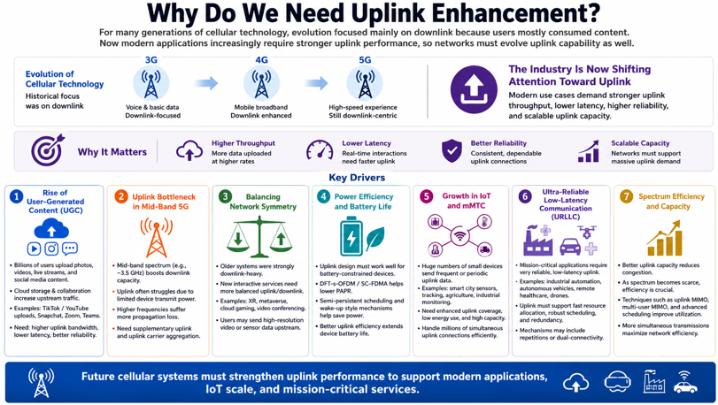
Figure 1. The traffic changed before the radio did. Uplink enhancement is a response to demand, rather than to a new capability that appeared in the radio itself.
Several key shifts have significantly increased the importance of uplink capabilities:
Rise of User-Generated Content (UGC) : Today, billions of users continuously upload photos, videos, live streams, and large files to social media, cloud storage, and collaboration tools.- Example: Instagram/TikTok live streaming, YouTube uploads, Snapchat, video conferencing (Zoom, Teams), cloud-based backups.
- This significantly increases demand for higher uplink bandwidth, lower latency, and enhanced reliability.
Uplink Bottleneck in Mid-Band 5G Networks : Mid-band (e.g., 3.5 GHz) spectrum provides substantial downlink capacity but typically struggles in uplink performance because:- Devices have limited transmission power compared to base stations.
- Higher frequencies experience greater propagation loss, weakening uplink signals.
- Therefore, new enhancements like supplementary uplink (SUL) and uplink carrier aggregation are required to improve uplink performance.
Balancing Network Symmetry : Historically, wireless networks were asymmetrical (high downlink, modest uplink). However, with new user behavior (interactive XR, gaming, video conferencing), symmetrical performance becomes critical.- Example: XR/metaverse applications where users send high-resolution video streams or sensor data upstream, demanding balanced uplink/downlink capabilities.
Power Efficiency and Battery Life : Devices constrained by battery life (e.g., smartphones, IoT sensors, wearables) benefit from efficient uplink transmission methods:- Technologies such as DFT-s-OFDM (SC-FDMA) waveforms lower the Peak-to-Average Power Ratio (PAPR), significantly enhancing device battery life during uplink transmission.
- Configured Grants (semi-persistent scheduling) and power-saving mechanisms (e.g., wake-up signals) ensure devices transmit uplink data efficiently, extending battery life.
Growth in IoT and Massive Machine-Type Communications (mMTC) : IoT devices primarily transmit data uplink (from device to cloud or server), generating a huge number of small, periodic uplink transmissions.- Example: Sensors in smart cities, asset tracking, agriculture sensors, and industrial monitoring.
- This scenario demands enhanced uplink coverage, low-energy consumption, and high capacity to handle millions of simultaneous connections efficiently.
Ultra-Reliable Low-Latency Communication (URLLC) : Mission-critical applications in industrial automation, healthcare, and automotive industries require extremely reliable uplink with very low latency.- Example: Remote surgery haptic feedback, autonomous vehicles uploading safety-critical data, industrial robotics sending immediate alerts.
- These scenarios require enhancements such as rapid resource allocation, robust uplink scheduling, and redundancy mechanisms (e.g., uplink repetitions, dual-connectivity uplink) to achieve ultra-high reliability.
Spectrum Efficiency and Capacity : Improving uplink capacity reduces congestion and increases spectral efficiency—crucial as spectrum resources become more expensive and limited.- Enhancements such as uplink MIMO, multi-user MIMO (MU-MIMO), and advanced scheduling enable more simultaneous transmissions, maximizing spectrum utilization and network efficiency.
Two things separate this from the usual capacity argument. The demand is closer to symmetric than it has ever been, and the binding constraint sits in the device rather than in the network.
The uplink gap is structural : device transmit power, UE antenna count and the TDD time split each limit the uplink on their own, so removing one leaves the other two in place.Mid-band carries both effects at once : a 3.5 GHz carrier gives the downlink its capacity and gives the uplink its propagation loss, and both come from the same frequency.The traffic changed before the features did : user-generated content, XR and live streaming arrived first, and the uplink capability to carry them followed.IoT and URLLC have opposite requirements : one needs many small transmissions at low energy, the other needs a single small transmission on time.Battery life is part of the requirement : an uplink gain paid for entirely in UE power costs battery life, so the two are measured together.
Technical Challenges and Mitigation
The technical challenges associated with uplink enhancement in 5G NR are driven by various factors including the inherent asymmetry of device and network capabilities, power constraints, spectrum characteristics, and diverse service requirements. Each factor carries its own mitigation, and the mitigations rarely overlap. This section is therefore organised as ten separate cases. The table below is indexed by technology, and it names what each 3GPP feature was introduced to solve. The sub-sections after it are indexed by problem, and they take one challenge at a time.
Addressing these technical challenges requires a combination of advanced network solutions (massive MIMO, coordinated reception, dynamic scheduling) and innovative device-level enhancements (efficient waveforms, intelligent power management). The ongoing evolution of 5G NR specifications (Release 16, 17, and beyond) continues to introduce targeted enhancements to systematically overcome these uplink-specific challenges, ultimately paving the way for more robust, reliable, and capable networks.
Figure 2 puts the ten challenges in one grid. Every panel keeps the same three rows : Issue, Impact and Mitigation. The panels run in the order the sub-sections below use. The grid therefore doubles as a map of the rest of this section. Read the Mitigation row against the table that follows, because the table lists the same techniques indexed by technique rather than by challenge.
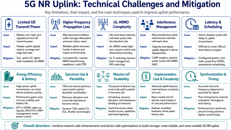
Figure 2. No single technique closes the uplink gap. Each challenge carries its own mitigation, and a real deployment needs several of them at the same time.
|
3GPP Technology |
Challenges Mitigated by the Technology |
|---|---|
|
Weak UE transmit power, poor cell-edge uplink coverage, indoor coverage gaps, and high-frequency propagation loss. |
|
|
Uplink Carrier Aggregation (UL CA) |
Limited uplink throughput and spectrum fragmentation. |
|
Uplink capacity and peak-rate limitation, with attention to UE power and antenna constraints. |
|
|
Practical UL-MIMO limitations by dynamically switching UE transmit chains across carriers. |
|
| Uplink capacity limitation and dense-user interference by spatially separating multiple simultaneous uplink transmissions. |
|
|
Weak uplink coverage and unreliable uplink reception by repeating uplink data transmission. |
|
|
Multi-TRP / CoMP uplink reception |
Uplink coverage, reliability, and interference problems by allowing multiple reception points to receive and process uplink signals. |
|
UL-MIMO and channel-estimation difficulty by helping the network estimate channels from different UE antenna paths. |
|
|
Channel-estimation limitations across carriers, especially when UE transmit-chain capability is limited. |
|
| Uplink latency and scheduling overhead by allowing UE transmission without repeated dynamic grant-request cycles. |
|
| Uplink latency by allowing shorter and more flexible transmission opportunities. |
|
|
UE battery drain and power-amplifier inefficiency by reducing uplink PAPR. |
|
|
UE energy consumption by reducing unnecessary active time. |
|
|
Energy waste and spectrum inefficiency by adapting active bandwidth to actual traffic needs. |
|
|
Implementation cost, complexity, and power-consumption burden for lower-cost or IoT-type devices. |
Limited Transmit Power of User Equipment (UE)
The fundamental challenge in enhancing uplink performance in cellular networks stems largely from the inherent limitations of transmit power in user equipment (UE), such as smartphones, IoT devices, and sensors. Unlike base stations, which have ample power sources and sophisticated cooling mechanisms, mobile devices are severely constrained by battery capacity, compact size, heat dissipation concerns, and strict regulatory guidelines, all of which significantly restrict their transmit power. Consequently, uplink signals transmitted from these devices are inherently weaker, particularly at cell edges or within challenging environments like indoor spaces, resulting in limited coverage and reduced achievable data rates. Addressing this challenge demands innovative technical solutions, including supplementary uplink (SUL), carrier aggregation (CA), higher-order modulation schemes, and advanced uplink MIMO (UL-MIMO) antenna configurations, enabling the cellular infrastructure to better capture, decode, and amplify these weaker uplink signals and thus deliver reliable connectivity across diverse conditions.
Issues : - Mobile devices (e.g., smartphones, IoT sensors) have strict limitations on transmit power due to battery life, size, heat management, and regulatory restrictions.
Implication: - Lower transmit power results in weaker uplink signals, leading to poorer coverage, especially at cell edges or indoors, thus limiting achievable data rates.
Mitigation: - Solutions like supplementary uplink (SUL), uplink carrier aggregation (CA), higher-order modulation, and advanced antenna configurations (UL-MIMO) help address this.
Higher Frequency Propagation Loss
One significant challenge in enhancing uplink performance arises from the inherent propagation characteristics of higher-frequency spectrum, notably mid-band frequencies around 3.5 GHz and high-band millimeter-wave (mmWave) frequencies. These higher frequencies suffer considerable signal attenuation due to their shorter wavelengths, making them more susceptible to blockage, reflection, and absorption by buildings, vegetation, and obstacles. Consequently, the uplink coverage at these frequencies is limited, creating notable gaps, especially indoors and in dense urban environments. This propagation loss severely impacts the reliability of uplink communications, necessitating strategic technical interventions such as supplementary uplink (SUL) that utilizes lower-frequency bands for extended reach, advanced beamforming through massive MIMO antenna arrays, and coverage-enhancement techniques including signal repetition (e.g., PUSCH aggregation factor) and multi-point reception (multi-TRP). These advanced measures are crucial in overcoming the coverage limitations and ensuring robust and consistent uplink connectivity across diverse deployment scenarios.
Issues : - Mid-band (e.g., 3.5 GHz) and high-band (mmWave) frequencies experience significant signal attenuation, causing uplink coverage gaps and poor indoor penetration.
Implication: - Achieving reliable uplink connections at higher frequencies is challenging, particularly in urban or dense environments.
Mitigation: - Deploying supplementary uplink (SUL) on lower-frequency bands, advanced beamforming (massive MIMO), and coverage-enhancement techniques (e.g., repetitions via PUSCH aggregation factor, multi-TRP reception).
Complexity of Uplink MIMO (UL-MIMO)
Implementing Uplink Multiple-Input Multiple-Output (UL-MIMO) presents distinct technical complexities compared to its downlink counterpart. In the uplink scenario, mobile devices typically have fewer antennas, limited transmit power, and simpler hardware, all of which constrain their capability to generate multiple simultaneous data streams. Consequently, UL-MIMO implementations require sophisticated strategies for precise synchronization between user equipment and the base station, careful management of the available transmit power to maintain signal quality, and advanced base station-side signal processing to effectively separate and decode the overlapping uplink streams. To address these practical challenges, technical innovations such as Uplink Transmit (Tx) switching—which dynamically allocates transmit antennas between different carriers—dynamic beam management, and refined Sounding Reference Signal (SRS) procedures (e.g., SRS Antenna Switching, SRS Carrier Switching) have been developed. These techniques collectively enable robust and efficient UL-MIMO operation and accurate channel estimation, thereby significantly enhancing overall throughput and reliability.
Issues : - Deploying UL-MIMO is more challenging than downlink MIMO because devices typically have fewer antennas and less transmit power.
Implication: - UL-MIMO requires careful management of transmit power, precise synchronization, and advanced signal processing at the base station, making practical implementations complex.
Mitigation: - Techniques such as UL Tx switching, dynamic beam management, and improved sounding procedures like SRS Antenna Switching and SRS Carrier Switching help realize effective uplink MIMO and precise channel estimation.
Interference Management and Coordination
Effective interference management and coordination is a critical challenge for enhancing uplink performance in modern cellular networks. In dense urban scenarios or areas with overlapping cells, multiple devices simultaneously transmitting uplink signals can lead to substantial interference. This interference significantly degrades signal quality, reduces overall network capacity, and limits achievable uplink data rates. Consequently, advanced and precise interference mitigation techniques become indispensable. Cellular networks now increasingly rely on sophisticated scheduling algorithms and dynamic power control methods to proactively minimize and manage interference. Furthermore, technologies such as Coordinated Multi-Point (CoMP) uplink reception—which involves multiple base stations jointly receiving and processing uplink transmissions—multi-user MIMO that spatially separates overlapping signals, and network-assisted interference cancellation (NAIC) have become vital. Collectively, these methods ensure efficient coordination and interference suppression, thereby enabling robust and reliable uplink connectivity even in highly challenging environments.
Issues : - Uplink signals from multiple devices often interfere, particularly in densely populated scenarios or overlapping cells, significantly degrading uplink capacity and quality.
Implication: - Accurate interference management becomes critical, requiring sophisticated scheduling and power control algorithms.
Mitigation: - Techniques such as coordinated multipoint (CoMP) uplink reception, dynamic power control, multi-user MIMO, and network-assisted interference cancellation (NAIC).
Uplink Latency and Scheduling Efficiency
Uplink latency and scheduling efficiency present significant challenges in supporting emerging latency-sensitive applications such as ultra-reliable low-latency communications (URLLC). Traditional uplink scheduling methods, which rely on a multi-step grant-request cycle, inherently introduce delays that are incompatible with stringent latency requirements often below 5 milliseconds. Consequently, conventional mechanisms become inadequate for real-time applications such as autonomous vehicles, remote surgery, and industrial automation. To effectively address these demanding latency constraints, cellular networks now adopt advanced uplink scheduling strategies including configured grants (also known as semi-persistent scheduling), enabling devices to transmit without repeated grant requests. Additionally, flexible scheduling units, such as mini-slots, allow transmissions to occur at shorter intervals. Proactive Hybrid Automatic Repeat Request (HARQ) retransmissions and preemptive scheduling further minimize response times, collectively ensuring the network can reliably meet tight latency targets and efficiently serve critical uplink use cases.
Issues : - Traditional uplink scheduling introduces latency due to grant-request cycles, making it challenging to support ultra-reliable low-latency communications (URLLC).
Implication: - Meeting stringent latency requirements (<5 ms) demands more efficient uplink scheduling mechanisms.
Mitigation: - Employing configured grants (semi-persistent scheduling), mini-slots (flexible scheduling), proactive HARQ retransmissions, and preemptive scheduling to minimize latency overhead.
Device Energy Efficiency and Battery Life
Improving device energy efficiency and battery life while enhancing uplink performance presents a crucial balancing act in cellular technology evolution. Uplink transmissions inherently require substantial energy, particularly when employing high transmit power, wider bandwidths, or advanced antenna configurations. Given that mobile devices, including smartphones, IoT sensors, and wearables, rely on limited battery capacities, prolonged or intensive uplink usage can significantly degrade device battery life, negatively affecting user experience and usability. Consequently, optimizing uplink capabilities demands energy-efficient approaches that do not compromise battery performance. To achieve this, modern cellular standards adopt specialized power-efficient waveforms, such as DFT-spread OFDM (SC-FDMA), along with advanced power-saving mechanisms, including wake-up signals to minimize unnecessary device activations, discontinuous reception and transmission (DRX/DTX) techniques to reduce idle energy consumption, dynamic bandwidth-part (BWP) management to scale energy usage according to real-time traffic needs, and intelligent power control algorithms. Together, these innovations ensure that robust and high-performance uplink communications coexist effectively with long-lasting device battery performance.
Issues : - Uplink transmission significantly impacts device battery life, especially at high transmit powers, broad bandwidths, or using multiple antennas.
Implication: - Improving uplink capabilities must not disproportionately reduce battery performance or device usability.
Mitigation: - Using power-efficient waveforms (e.g., DFT-s-OFDM), power-saving features (wake-up signals, discontinuous reception/transmission (DRX/DTX), bandwidth-part (BWP) management), and intelligent power control mechanisms.
Spectrum Utilization and Flexibility
Efficient and flexible utilization of spectrum presents a fundamental challenge in enhancing uplink performance, particularly within shared frequency bands used by both uplink and downlink transmissions, such as those operating under TDD arrangements. Sharing the same spectral resources dynamically introduces complexities in managing interference between uplink and downlink channels, requiring precise timing coordination and dynamic allocation strategies to avoid harmful cross-link interference. Consequently, networks must be capable of rapidly and flexibly adjusting uplink and downlink ratios based on instantaneous traffic demands and interference conditions. To achieve this level of spectral efficiency and flexibility, cellular networks implement advanced techniques, including dynamic TDD patterns that adapt in real-time, uplink carrier aggregation (CA) for boosting uplink throughput, supplementary uplink (SUL) utilizing lower-frequency bands to complement coverage, and flexible numerologies that allow tailoring the waveform and resource allocation according to specific requirements. Collectively, these measures enable the optimized use of available spectrum, ensuring robust uplink performance while maximizing overall spectral efficiency.
Issues : - Efficient uplink spectrum utilization is challenging, particularly when uplink and downlink share the same band (TDD), requiring careful management to avoid interference and optimize resource allocation.
Implication: - Dynamically adjusting uplink/downlink ratios and efficiently managing uplink resources become critical.
Mitigation: - Dynamic TDD patterns, uplink carrier aggregation, supplementary uplink, and flexible numerologies to maximize spectral efficiency and minimize cross-link interference.
Scalability for Massive IoT and Device Density
Supporting massive-scale IoT deployments, characterized by extremely high device density, creates significant challenges for the scalability of uplink capabilities in modern cellular networks. Unlike traditional broadband connections, IoT scenarios typically involve thousands of devices within a single cell, each periodically transmitting small packets of uplink data simultaneously or in quick succession. This dense environment greatly stresses the network's capacity for efficient scheduling, timely resource allocation, and interference management. As device densities grow, traditional uplink resource-allocation methods become inefficient and insufficiently scalable. To effectively address these scalability issues, cellular networks increasingly employ advanced techniques such as grant-free configured grants, allowing IoT devices to transmit data without explicit scheduling requests, significantly reducing signaling overhead. Enhanced random-access procedures further streamline device connections, while repetition-based transmission methods (e.g., PUSCH aggregation factor) enhance coverage reliability, particularly for devices located in challenging signal environments. Additionally, optimized signaling protocols tailored for massive IoT reduce network congestion and improve responsiveness. Together, these solutions ensure that cellular networks can efficiently accommodate a massive number of connected devices, maintaining robust performance and reliability even in extreme device-density scenarios.
Issues : - Supporting thousands of IoT devices in the same cell demands efficient handling of many simultaneous or near-simultaneous uplink transmissions.
Implication: - High-density scenarios stress scheduling, resource allocation, and interference management capabilities.
Mitigation: - Grant-free configured grants, improved random-access procedures, repetition-based coverage enhancements (e.g., PUSCH aggregation factor), and optimized signaling protocols to handle large-scale IoT traffic effectively.
Implementation Complexity and Cost
The implementation of advanced uplink enhancements introduces significant complexity and cost challenges, particularly for UE such as smartphones, IoT devices, and other mass-market products. Technologies like UL-MIMO, sophisticated signal processing algorithms, and higher-order modulation schemes substantially elevate hardware complexity, leading to increased manufacturing costs, greater power consumption, and potential impacts on device size and form factor. This complexity poses a critical barrier to widespread adoption, especially in price-sensitive consumer markets and massive IoT deployments where affordability and power efficiency are paramount. To effectively manage this trade-off, industry stakeholders and standardization bodies have introduced strategies such as defining Reduced Capability (RedCap) UE profiles, which specify simpler hardware configurations, reduced bandwidth, and fewer antennas. Additionally, tiered uplink feature sets have been developed, allowing devices to selectively support only essential functionalities according to specific application requirements. By adopting these measures, cellular technology aims to balance advanced uplink performance and network capabilities with practical considerations of device cost, complexity, and energy efficiency, thereby facilitating broader market adoption and device accessibility.
Issues : - Advanced uplink enhancements (e.g., multi-antenna UE configurations, complex signal processing) increase device cost and complexity.
Implication: - Balancing complexity, performance, and cost becomes challenging, particularly for affordable mass-market and IoT devices.
Mitigation: - Defining reduced capability (RedCap) UE profiles, simplified hardware requirements, and tiered uplink feature sets to manage complexity while ensuring broad adoption.
Synchronization and Timing Accuracy
Precise synchronization and timing accuracy between user equipment and the network are foundational requirements for efficient uplink transmission, especially in advanced scenarios involving MIMO, multi-user scheduling, or coordinated multi-point reception. Uplink transmissions must be tightly aligned in time and frequency to avoid inter-symbol interference, maintain orthogonality across users, and enable accurate channel estimation at the receiver. Even small timing mismatches can lead to degraded signal quality, reduced throughput, and increased error rates—issues that are particularly critical for latency-sensitive services such as URLLC or real-time industrial control. Furthermore, when multiple base stations or transmission reception points (TRPs) are involved in uplink reception, as in multi-TRP setups or CoMP, the margin for timing error becomes even narrower. Addressing this challenge requires a combination of enhanced synchronization protocols, refined timing advance algorithms to precisely calibrate UE transmission timing, and tighter control feedback loops between the network and the device. These mechanisms ensure that uplink signals from multiple devices arrive within the required temporal window, preserving the integrity of high-speed, multi-layer, and time-critical transmissions.
Issues : - Achieving precise synchronization between the network and devices is critical, particularly in uplink transmissions involving MIMO or multi-point reception.
Implication: - Inaccurate timing degrades channel estimation, reduces effective throughput, and affects latency-sensitive applications.
Mitigation: - Enhancing synchronization protocols, high-accuracy timing advance management, and tighter control loops within the network and device.
Which Technique for Which Problem ?
The table in the section above maps each technology to the challenge it addresses. It does not say which technology to try first, and on a real link that is the question. A UE has a fixed number of transmit chains and a fixed power budget. Several of these techniques therefore compete for the same hardware, and enabling one can rule another out. Sorting them by the limit that actually binds is more useful than sorting them by name. Four limits cover almost every case, and each one gets a sub-section below.
Coverage-limited Uplink
The UE cannot reach the cell reliably, and the downlink is fine. This is the cell-edge and indoor case, and it is the most common one on a mid-band carrier. Rate is not the problem here. The right techniques are the ones that spend time or bandwidth in exchange for reach.
Supplementary uplink first . It moves the uplink to a low band, so it changes the propagation rather than compensating for it. Nothing else on this list does that.PUSCH repetition next . The field pusch-AggregationFactor ENUMERATED {n2, n4, n8} repeats a transport block across slots, and a configured grant carries the same idea in repK ENUMERATED {n1, n2, n4, n8}. Release 17 extended it to repK-v1710 ENUMERATED {n12, n16, n24, n32}.Multi-TRP reception last . It costs network hardware rather than UE configuration, so it is the slowest of the three to deploy.
One warning belongs with repetition. It divides throughput by the repetition factor, so n8 spends eight slots on a single transport block. A link that is short of capacity as well as coverage gets worse, not better.
Capacity-limited Uplink
Coverage is adequate and the rate is not. This is the cell-centre case, and it is where the UE still has power budget left. The techniques here add streams or add carriers. Both of them need the signal quality that a cell edge does not have, which is why this list and the one above share nothing.
UL-MIMO first . The field maxRank INTEGER (1..4) in PUSCH-Config sets the ceiling, and maxRank-v1810 INTEGER (5..8) raised it above four in Release 18.Uplink carrier aggregation next . It adds bandwidth rather than streams, so it does not depend on the antenna correlation the way MIMO does.MU-MIMO on the network side . It raises the capacity of the cell rather than the rate of one UE, so it answers a different question from the other two.
UL-MIMO carries a dependency worth stating. The network needs a channel estimate for every UE antenna before it can separate the streams, and SRS antenna switching is what produces those estimates. A UE with one transmit chain cannot sound the other antennas at the same time, so its rank is capped whatever maxRank says.
Latency-limited Uplink
Throughput and coverage are both adequate, and the delay before the first bit leaves is the problem. The grant request cycle is the part to remove. A scheduling request, a grant, and only then a transmission is three trips across the air interface before any data moves.
Configured grant first . Type 1 arrives entirely in RRC through rrc-ConfiguredUplinkGrant, so the UE transmits with no request and no activation DCI. Type 2 keeps the RRC configuration and adds an activation DCI.Mini-slot scheduling next . It shortens the transmission itself, rather than the delay before it.Proactive HARQ and pre-emption last . Both reduce the cost of a failure rather than the delay of a success.
The price here is spectrum. A configured grant reserves resources whether or not data arrives, so a cell full of low-latency UEs carries reservations that mostly go unused.
Energy-limited Uplink
The link works and the battery does not last. This is the IoT and wearable case, and it reaches every smartphone once the uplink runs for long enough. Two separate things consume the energy : the waveform while transmitting, and the time spent awake and not transmitting.
DFT-s-OFDM for the waveform . The field transformPrecoder ENUMERATED {enabled, disabled} appears in both PUSCH-Config and ConfiguredGrantConfig, so NR chooses the waveform per configuration rather than once for the whole uplink.Then reduce the time awake . The wake-up signal ps-WakeUp-r16 in DCP-Config-r16, DRX and bandwidth part adaptation all reduce the same idle energy in different ways.RedCap last . It is a device profile rather than a configuration, so it is decided when the device is designed and not when the cell is planned.
The waveform choice is the one with a hidden cost, and 38.211 states it plainly. The caption of Table 6.3.1.5-47 reads : up to 8 layers are supported with transform precoding disabled and up to one layer with transform precoding enabled. A UE therefore gives up UL-MIMO completely when it enables transform precoding for the PAPR benefit.
Three of these choices conflict directly, and the conflicts are easier to plan around once they are named.
SUL and uplink CA want the same spectrum . Both of them need a low band. A network with one low band can give it to SUL for reach or to CA for rate, and not to the same UE for both.UL Tx switching states its own conflict . The field uplinkTxSwitchingOption-r16 ENUMERATED {switchedUL, dualUL} chooses between putting both transmit chains on one carrier and keeping one chain on each.Repetition and UL-MIMO optimise opposite things . One spends time for reliability and the other spends power for rate. A link that needs both is a link that needs a different band.
Name the limit before naming the technique : coverage, capacity, latency and energy have four different first answers, and the wrong first answer costs configuration effort for nothing.Transmit chains are the scarce resource : SRS antenna switching, UL Tx switching and UL-MIMO all draw on the same small number of them.Every technique on this page has a price : repetition costs throughput, MIMO costs power, configured grant costs spectrum, and DFT-s-OFDM costs rank.SUL changes the propagation, the rest compensate for it : that is the reason it sits first on the coverage list.
LTE Uplink and NR Uplink Compared
Several terms on this page came from LTE, and they do not all mean the same thing in NR. A reader who learned the uplink on LTE will recognise most of the mechanisms below and will find two of them changed. The table puts the two side by side, and it uses the RRC field name from each specification as the evidence. LTE rows were read from 36.331 v19.3.0 and NR rows from 38.331 v19.3.0.
Mechanism |
LTE, 36.331 v19.3.0 |
NR, 38.331 v19.3.0 |
What changed |
|---|---|---|---|
Uplink waveform |
No field. The uplink is DFT-s-OFDM throughout, and 36.331 has no transformPrecoder. |
transformPrecoder ENUMERATED {enabled, disabled} in PUSCH-Config and ConfiguredGrantConfig |
NR makes the waveform a configuration choice rather than a property of the uplink. |
Uplink spatial multiplexing |
transmissionModeUL-r10 ENUMERATED {tm1, tm2, spare6, spare5, spare4, spare3, spare2, spare1} in AntennaInfoUL-r10 |
maxRank INTEGER (1..4) in PUSCH-Config, extended by maxRank-v1810 INTEGER (5..8) |
LTE offers two modes and has added none since Release 10, with six code points still spare. NR carries a rank number instead, and Release 18 raised the ceiling above four. |
Low band uplink pairing |
No equivalent. 36.331 contains no supplementaryUplink field. |
supplementaryUplink in ServingCellConfig and ServingCellConfigCommon |
SUL is new in NR, and it exists because NR put the downlink on mid band where LTE did not. |
Grant free uplink |
sps-ConfigUL inside SPS-Config |
configuredGrantConfig in BWP-UplinkDedicated, with sps-Config kept for the downlink only |
The mechanism survives and the name does not. LTE calls both directions SPS, and NR splits the two names by direction. |
Repetition for coverage |
Coverage-enhancement fields such as pucch-NumRepetitionCE-Format1 and mpdcch-NumRepetition, tied to the CE modes used by MTC devices |
pusch-AggregationFactor ENUMERATED {n2, n4, n8} in PUSCH-Config, and repK in ConfiguredGrantConfig |
LTE treats repetition as a device category feature. NR makes it an ordinary PUSCH parameter available to any UE. |
Sharing transmit chains across carriers |
No equivalent. 36.331 contains no TxSwitch field of any kind. |
uplinkTxSwitching-r16 in UplinkConfig, and BandCombination-UplinkTxSwitch-r16 |
The LTE half of an EN-DC pair is switched by NR signalling, so the whole feature lives in 38.331. |
Uplink bandwidth adaptation |
No equivalent. 36.331 has no bandwidth part concept. |
BWP-UplinkDedicated, with the active bandwidth part changed while connected |
NR can shrink the active uplink bandwidth to save UE power, and LTE cannot. |
The grant-free row is the one that causes arguments. LTE really does configure the uplink through sps-ConfigUL inside SPS-Config, so calling an NR configured grant uplink SPS uses the LTE name correctly and the NR name incorrectly. NR keeps sps-Config for the downlink alone. An NR log will therefore never show SPS on the uplink, whatever the feature was called in the design document.
The spatial multiplexing row is the one that surprises people. LTE described the uplink with a transmission mode, in the same way it described the downlink, and it stopped at two of them in Release 10. Six code points in that enumeration are still marked spare fifteen years later. NR abandoned the mode concept for the uplink and configured a rank instead, which is why raising the ceiling in Release 18 needed one new field rather than a new mode.
Two names, one mechanism : LTE uplink SPS and the NR configured grant do the same job under different names, and only the NR name is right in NR.Two mechanisms with no LTE ancestor : SUL and UL Tx switching have no field in 36.331 at all, so LTE experience gives no intuition for either.The uplink transmission mode did not survive : NR replaced tm1 and tm2 with a rank integer, and that is what made an eight layer uplink a field change rather than a redesign.Repetition moved from a category to a parameter : LTE tied it to CE modes for MTC devices, and NR offers it to any UE through PUSCH-Config.
Impact on Use Cases
Figure 1 names seven drivers, and every section since then has taken the network side of them. This one takes the user side. Four cases cover most of what the uplink is now asked to carry, and each binds on a different limit from the technique section above. The application itself is not the interesting part. Which limit it reaches first is.
XR and Cloud Gaming
Pose data, controller input and camera frames all travel upstream, and they travel continuously rather than in bursts. The rate is moderate and the delay budget is tight, which makes this the clearest latency case on the list. Jitter matters more here than the mean rate does.
Binds on : latency first, capacity second.Techniques : configured grant to remove the request cycle, mini-slot scheduling to shorten the transmission, and enough rank to carry the rate without raising the transmit power.Watch for : a configured grant sized for the average frame. An XR stream is not constant, and a grant that fits the average will delay every frame above it.
Live Streaming and User-Generated Content
A phone uploads video for minutes at a time, from wherever the user happens to be standing. The rate has to be sustained rather than peak, and the radio conditions change during the session. This is the case that turned the uplink from an engineering concern into a commercial one.
Binds on : capacity in the cell centre, coverage at the edge, and the same session can move between the two.Techniques : UL-MIMO and uplink carrier aggregation where the signal allows, SUL where it does not, and UL Tx switching to move the second transmit chain to whichever carrier is carrying the traffic.Watch for : the handover from the capacity list to the coverage list in the middle of a stream. The two lists share no techniques, so the transition is where a stream stalls.
Industrial IoT and URLLC
This case brings small packets, a hard deadline, and a reliability target reached through repetition rather than through rate. A sensor reading or a robot alert is a few dozen bytes, so throughput is close to irrelevant. A packet that arrives late and a packet that arrives corrupt are the same failure.
Binds on : latency and reliability at the same time, which is the hardest pair on this page.Techniques : configured grant for the deadline, PUSCH repetition and multi-TRP reception for the reliability, and accurate timing advance to keep the transmissions orthogonal.Watch for : device density. A thousand sensors with configured grants reserve a thousand sets of resources, and the scheduling problem moves from the device to the cell.
Fixed Wireless Access
A household uploads through a device that never moves and never runs on a battery. This case removes most of the constraints that shape the rest of this page. That makes it the simplest one here, and also the least representative.
Binds on : capacity, and almost nothing else.Techniques : full rank UL-MIMO, uplink carrier aggregation, and an external or carefully placed antenna. Every power-saving mechanism above is irrelevant to a mains-powered CPE.Watch for : reading FWA results as evidence about handsets. A fixed antenna and a mains supply remove the antenna limit and the power limit at once, and those two limits are what the rest of this page is about.
The limit changes, the technique list changes with it : four cases here reach four different limits first, and each one starts from a different sub-section above.Rate is the wrong measure for two of these four : XR is bound by delay and industrial IoT by reliability, and neither improves when the peak rate does.One session can cross two cases : a live stream moves from the capacity list to the coverage list when the user walks to the cell edge, and none of the techniques transfers.FWA removes two constraints rather than working around them : take away the battery and the antenna limit, and the uplink problem reduces to ordinary capacity planning.
Which Release Introduced What
The sections above name Release 15, 16, 17 and 18 features in passing. A reader needs that mapping in one place, and needs it when checking a device or a network against one of those releases. Evidence helps more than a claim does. 38.331 stamps the release into the name of every field it adds. The field name is therefore the evidence. A field with no suffix at all dates from Release 15. Every row below was taken from 38.331 v19.3.0.
Feature |
First release |
Field in 38.331 v19.3.0 |
Extended by |
|---|---|---|---|
Release 15 |
supplementaryUplink in ServingCellConfig, with no release suffix |
supplementaryUplinkRelease-r16 |
|
Release 15 |
configuredGrantConfig in BWP-UplinkDedicated |
configuredGrantConfigToAddModList-r16, which allows more than one configuration |
|
Downlink semi-persistent scheduling |
Release 15 |
sps-Config in BWP-DownlinkDedicated |
sps-ConfigToAddModList-r16 |
Release 16 |
uplinkTxSwitching-r16 in UplinkConfig, and uplinkTxSwitchingOption-r16 ENUMERATED {switchedUL, dualUL} in CellGroupConfig |
uplinkTxSwitching-2T-Mode-r17, uplinkTxSwitchingMoreBands-r18, uplinkTxSwitching3Tx-r19 |
|
Release 16 |
pusch-RepTypeIndicator-r16 ENUMERATED {pusch-RepTypeA, pusch-RepTypeB} |
dmrs-BundlingPUSCH-RepTypeBPerBC-r17 |
|
Release 16 |
ps-WakeUp-r16 in DCP-Config-r16 |
no later extension of this field |
|
Release 17 |
redCap-ConfigCommon-r17 in SIB1-v1700-IEs |
eRedCapPriority-r18 and intraFreqReselection-eRedCap-r18 |
Two rows need a note, because the shorthand used elsewhere on this page has aged. UL Tx switching arrived in Release 16 as a two-transmitter feature, and the introduction above describes it that way. It did not stay there. Release 17 added a 2T mode and a dual-UL transmit state, Release 18 opened the feature to more than one band pair, and Release 19 added a three-transmitter variant.
The other is a naming point. Configured grant and semi-persistent scheduling are used as synonyms in several places on this page, and LTE did treat them as one mechanism. NR splits them by direction instead. The field configuredGrantConfig sits under BWP-UplinkDedicated and sps-Config sits under BWP-DownlinkDedicated, so an NR log will not show SPS on the uplink.
One practical use follows from the table. A UE capability report names the same fields, so a band combination carrying BandCombination-UplinkTxSwitch-r16 shows a device that implements the Release 16 form of the feature. An absent uplinkTxSwitching3Tx-r19 in the configuration shows a network that is not asking for the Release 19 form. The release column and the field column answer different questions, and both are worth checking before a feature is called supported.
The -rNN suffix is the release check : it is the cheapest one available, and it needs no release notes to read.UL Tx switching is no longer a two-antenna feature : uplinkTxSwitching3Tx-r19 brings a third transmit chain into scope.Configured grant is the uplink name : NR keeps sps-Config for the downlink, so the two terms are not interchangeable here.The uplink work did not start at Release 16 : SUL and configured grant are both Release 15. Release 16 is where the pace changed.Read the field, not the marketing name : a vendor feature name says nothing about which release a UE has to support to use it.
Reference
- 36.331 - E-UTRA; Radio Resource Control (RRC) protocol specification, v19.3.0 (Release 19)
- 38.211 - NR; Physical channels and modulation, v19.4.0 (Release 19)
- 38.331 - NR; Radio Resource Control (RRC) protocol specification, v19.3.0 (Release 19)
- 5G Uplink Enhancement Technology - White Paper (ZTE)
- 5G Uplink Enhancement Techniques - Whitepaper (Mediatek)
- 2023 Switched Uplink in 5G-NR: Benefit & Deployment Consideration - Qualcomm
- 3GPP Release 17: Completing the first phase of the 5G evolution - Qualcomm
- T-Mobile Achieves Record-Breaking Uplink Speeds on its 5G Standalone Network Using UL Tx Switching - everythingRF (Feb 2024)
YouTube
- 5G Uplink-Tx-Switching feature explained (Uplink Carrier Aggregation) - Henrik (May 2024)