Serial
Arduino support Serial Communication (UART). With this, you can communicate with PC that is connected to your Arduino board or Communicate with other Arduino modules that support the serial communication interface. In this page, I will describe on Arduino Serial interface from the high level connection to the very bottom level (Register level).
- Basic Connection Test
- Basic Sample Programs
- Software Serial
- Controlling ESP8266 with Serial Port
- Minimal C programming for Tx Only Serial Communication
- Registers for Serial Communication
With Arduino board, you can send any data from the PC to Arduino board or from Arduino Board to PC using Serial Communication. But you don't need any separate serila port (e.g, RS 232 port) for this comunication. You can use the USB port that you using to program Arduino to do serial communication as shown below.

For the details of programming the serial communication, you may refer to Arduino Reference : Serial page. But once you have basic understandings on this communication.. it is only the matter of time and practice to get further details.
In terms of software, the serial communication goes as below. As you know, if you upload the program the program is running on Arduino chipset. When the program runs Serial library, it communicate with Arudio Serial Monitor program as shown below.
When Serial.read() function is executed, it recieves the data sent from Arduino Serial Monitor. When Serial.pring() function is executed, Arduino board send data to PC serial port and eventually carried to Arduino Serial Monitor.

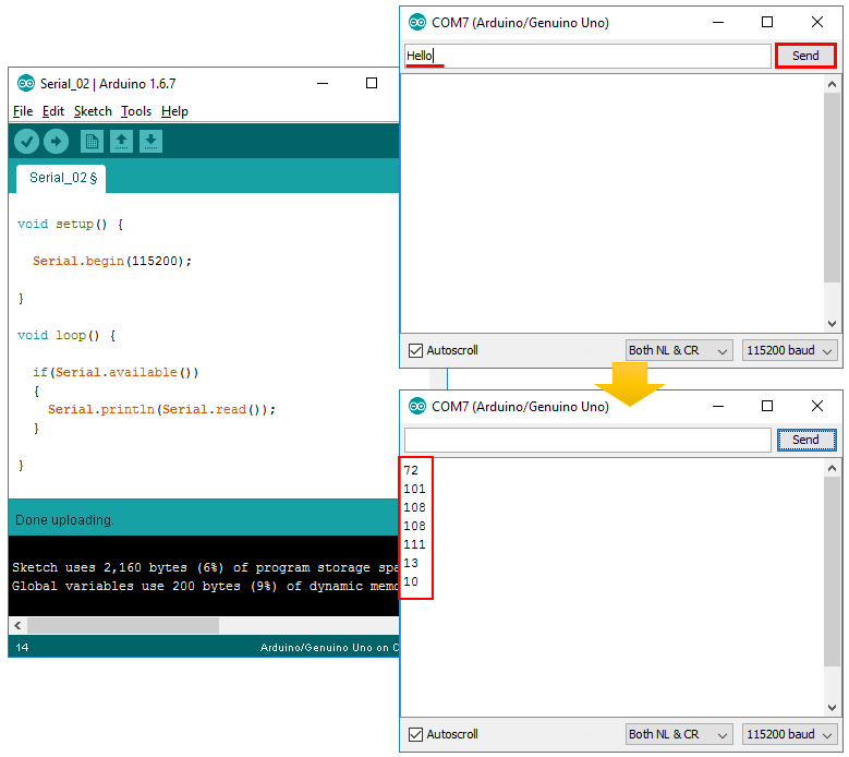
Following is an example for Arudino Serial communication. As you see, it is very simple. The only thing you have to be careful about is the data rate(baud rate) configuration in Serial.begin() function. You have to specify the same data rate in Serial.begin() function and Serial Monitor program as shown below.

void setup() {
Serial.begin(115200);
}
void loop() {
if(Serial.available())
{
Serial.println(Serial.read());
}
}
Example 03 > Serial.readString()
void setup() {
Serial.begin(115200);
}
void loop() {
if(Serial.available())
{
Serial.println(Serial.readString());
}
}

Software Serial is a software tool (library) that can turn ordinary digital I/O pins into Serial Ports. Since Arduino Uno has only one default serial ports, this software library can be very useful for the application that require multiple serial ports.
In this section, I will show you how to verify that the software serial ports works and this would be a good troubleshooting method to figure out if it is the programming issue / Arduino board issue or the device that is connected to the software serial port.
For this test, I built a connection between the pins that are assigned for software serial port and Arduino default Serial port as shown below. In this test, I assigned the digital port 2 and 3 as software serial port Rx / Tx port.

#include <SoftwareSerial.h>
SoftwareSerial mySerial(2, 3);
void setup() {
Serial.begin(115200);
mySerial.begin(115200);
}
void loop() {
mySerial.print("HELLO\n\r");
if(Serial.available()) {
Serial.print(Serial.readString());
};
delay(1000);
}
#include <SoftwareSerial.h>
SoftwareSerial mySerial(2, 3);
void setup() {
Serial.begin(115200);
mySerial.begin(115200);
}
void loop() {
Serial.print("HELLO\n\r");
delay(1000);
if(mySerial.available()) {
Serial.print("Echo :" + mySerial.readString());
delay(1000);
};
}
Controlling ESP8266 with Serial Port
There are many modules that are communicating or controlled by serial communication. One of the typical examples is the WiFi module ESP8266. Refer to ESP8266 Example Page for the details.
Minimal C programming for Tx Only Serial Communication
The examples described above would be the easiest way to use the Arduino Serial communiation port. It might be good enough for general users just to utilize various modules. However, if you really want to understand how these serial communication works at the microcontroller level, you need to understand all the I/O Registers related to the serial port. These registers are well described in Registers for Serial Communication. However, just reading through the document would not give you any tangible (touchable) understanding. You need to get the intuitive understanding by real programming. I will give you very simple but showing the way to control each and every registers related to the serial communication interface of AVR chipset. The source code for simpletx() is based on Simple Tx (Arduino Play Ground) and the description (explanation) is from me. This is very simple / short code, but it will give you all the details on how to controll all the registers for serial communication port.
To run the example shown here, create a c file named uart_c.c and type in following code.
uart_c.c ======================================================
#include <avr/io.h>
#define BAUDRATE (16000000/16/9600-1)
void simpletx( char * string ){
if (UCSR0B != (1<<TXEN0)){
UBRR0H = (unsigned char)(BAUDRATE>>8);
UBRR0L = (unsigned char)BAUDRATE;
UCSR0A = 0;
UCSR0B = (1<<TXEN0);
UCSR0C = (3<<UCSZ00);
}
while (*string){
while ( !( UCSR0A & (1<<UDRE0)) );
UDR0 = *string++; //send the data
}
}
int main(void) {
simpletx("Hello World !");
return 0;
}
Then you can compile and upload the program onto Arduino chipset by running following four commands in sequence (Refer to Programming in C page if you want to get further details on each of these steps)
"C:\Program Files (x86)\Arduino\hardware\tools\avr\bin\avr-gcc" -Os -DF_CPU=16000000UL -mmcu=atmega328p -c -o uart_c.o uart_c.c
"C:\Program Files (x86)\Arduino\hardware\tools\avr\bin\avr-gcc" -mmcu=atmega328p uart_c.o -o uart_c
"C:\Program Files (x86)\Arduino\hardware\tools\avr\bin\avr-objcopy" -O ihex -R .eeprom uart_c uart_c.hex
"C:\Program Files (x86)\Arduino\hardware\tools\avr\bin\avrdude" -C "C:\Program Files (x86)\Arduino\hardware\tools\avr\etc\avrdude.conf" -F -V -c arduino -p ATMEGA328P -P COM3 -b 115200 -U flash:w:uart_c.hex
After you uploaded the program to Arduino board, run Serial port monitor and you would get the result as shown below.
NOTE : Make it sure that you set the baud rate to be '9600 baud' in serial port monitor because this is the rate specified in C source code.

Now let's go through the source code line by line and how they are related to the corresponding register manipulation.
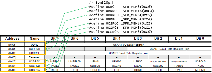
First you need to understand the variables linked to each of the registers. They are defined in ioxxx.h file as show below (In my case, I am using Arduino UNO which is using ATmega328 chipset. That's why iom328p.h is used when I compile the code. If you are using a different chipset, you need to open up the header file that matches the chipset you are using)
The first step is to check the status of the bit 3 (TXEN0) of UCSR0B with the following if statement. If this is set to be '1', it assumes that all the serial port configurations are already done and skips the serial port configuration process.

Following three lines is for converting the baud rate into the value for UBRR register and setting the corresponding register.

Following line is to set the bit 5 (UDRE0) of UCSR0A register.

Following is to set the bit 3( TXEN0 bit) of UCSR0B register to be '1' and set all other bits to be '0'. By this the UART TX pin gets enabled.

Following is to set bit 0 and 1 (UCSZ00 and UCSZ01) to be '1' and set all other bits to be '0'. With this single line, several configurations of UART is set together as highlighted in red box shown below.


With this, UART configuration is done. The next step is to send some data using the serial port.
The first step is to check whether UDR0 (Data Register) is ready to be written or not. When this bit is set to be '0' (UDR0 is not ready to be written), the while loop continues and when this bit is set to be '1'(UDR0 is ready to be written), the while loop stops and proceed to the next step (writing the data to UDR0).

Following is to write a single character to UDR0 register.

Just for your refernece, I copied all the variables and macros to help you understand the source code. If you are using different chipset, you would need to open up different iomXXX.h file)
// sfr_def.h
#define _SFR_MEM8(mem_addr) (mem_addr)
#define _SFR_MEM16(mem_addr) (mem_addr)
// iom328p.h
#define UBRR0 _SFR_MEM16(0xC4)
#define UBRR0H _SFR_MEM8(0xC5)
#define UBRR0L _SFR_MEM8(0xC4)
#define UCSR0A _SFR_MEM8(0xC0)
#define MPCM0 0
#define U2X0 1
#define UPE0 2
#define DOR0 3
#define FE0 4
#define UDRE0 5
#define TXC0 6
#define RXC0 7
#define UCSR0B _SFR_MEM8(0xC1)
#define TXB80 0
#define RXB80 1
#define UCSZ02 2
#define TXEN0 3
#define RXEN0 4
#define UDRIE0 5
#define TXCIE0 6
#define RXCIE0 7
#define UCSR0C _SFR_MEM8(0xC2)
#define UCPOL0 0
#define UCSZ00 1
#define UCPHA0 1
#define UCSZ01 2
#define UDORD0 2
#define USBS0 3
#define UPM00 4
#define UPM01 5
#define UMSEL00 6
#define UMSEL01 7
#define UDR0 _SFR_MEM8(0xC6)
#define UDR0_0 0
#define UDR0_1 1
#define UDR0_2 2
#define UDR0_3 3
#define UDR0_4 4
#define UDR0_5 5
#define UDR0_6 6
#define UDR0_7 7
Registers for Serial Communication

< USART I/O Data Register >

< USART Baud Rate Registers >

< USART Control and Status Register n A >

< USART Control and Status Register n B >

< USART Control and Status Register n C >

Referemce :
[2] Simple Serial Communications With AVR Libc
[3] Simple Tx (Arduino Play Ground)