WiFi - ESP8266
I like most part of Arduino but there were something I am not so satisfied with it. It doesn't come out with any means of internet connection. To overcome this drawback, I first thought of using Ethernet shield just because I thought it would be simpler than using WiFi shield. However, I was told that the original Ethernet shield is not available any more in the market. I bought a clone version of the eithernet shield, but failed to make it work. And then I was thinking of WiFi shield, but it was too expensive (around 100 bucks) which is over twice as expensive as Arduino board itself. So I didn't even try this. At last, I came to learn about ESP8266 WiFi module that cost less than 10 bucks. At first, I was a little reluctant to try it because I was not sure if it really works well as most of the tutorials or YouTube shows, but I decided to try it anyway since there is no alternatives for me. Luckily it worked much easier than I was concerned about. In this tutorial, I want to share you with my experience with the WiFi module based on ESP8266 chipset. Even though using the exactly same chipset, your experience would not be as smooth as mine depending on the specific modules that you get or the firmware versions of the chipset. So don't expect that you will make it work at first try :)
NOTE : This tutorial can be a good example to show you how to utilize the serial commuincation on Arduino board.
This note will be very long and continuously revised and added. Followings are the list of topics covered as of now.
Basic Configuration Setup and Connection Check with No Programming
Step 1. Load an empty sketch to Arduino Board
Step 2. Confirm Serial Communication working
Step 3. Initialize (Reset) the WiFi Module
Step 4. Check the firmware version of WiFi Module
Step 5. Set the device mode to make it function as both 'Client and AP (Mode 3)'.
Step 6. Search WiFi Access Point
Step 7. Join onto the Access Point (Connect to AP)
Step 8. Confirm on the assigned IP
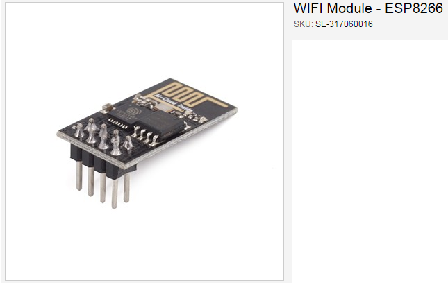
Basic function and pin mapping for the most of ESP8266 module are same (or similar), but the detailed behavior may be a little different depending on the firmware version or manufacturer of the module. So my recommendation is to search things about the modules and pick something from the manufacturer that provide the detailed documentation. The one that I purchased is shown below (Actually this was the only one that I could get from a local electronics shop in my area).
http://www.rpelectronics.com/se-317060016-wifi-module-esp8266.html
Followings are the descriptions on the pins out of the module. I think these pin mapping would be same for all the module that looks like this.
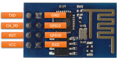
The function of each pins are as follows. One thing to be VERY CAREFUL is that you have to put 3.3V (not 5V) in VCC. You would burn the chips on the board if you apply higher voltage.
GND : Circuit Ground
TX : UART0 Transmit
RX : UART0 Receive
GPIO2 : General Purpose I/O
GPIO0 : General Purpose I/O
CH_EN : Chip Enable, Active High
RST : Reset, Active Low
VCC : Circuit Power, +3.3V DC
Basic Configuration Setup and Connection Check with No Programming
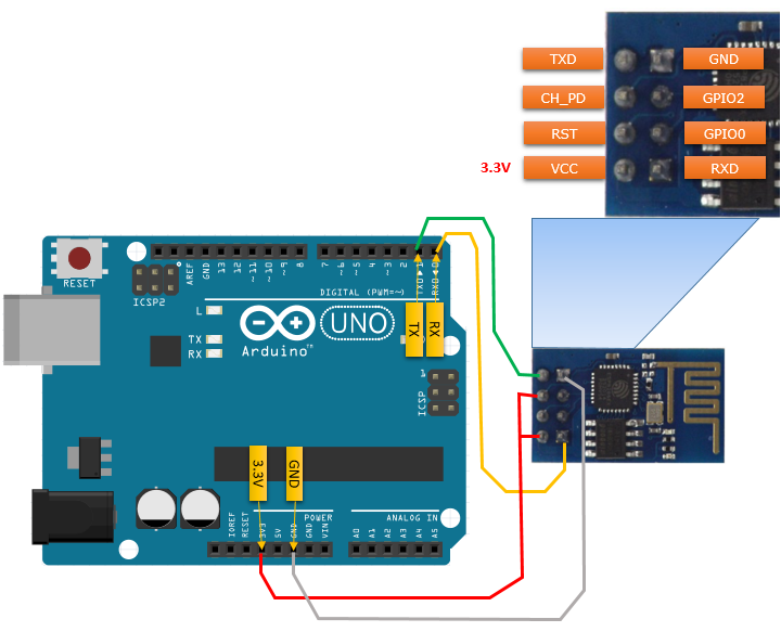
The connection between the esp8266 module and Arduino board is as follows. As you may guess from this connection, the communication between Arduino board and the esp8266 module is done via UART port. It implies that ESP8266 module is a kind of a translator converting WiFi protocol to UART (Serial Port) protocol and vice versa.
I want to point out a couple of important points that you need to pay attention to.
Note 1 : VCC of the esp8266 is connected to 3.3 V of Arduino. Do not ever connect 5V output of Arduino directly to the VCC of the esp8266 module. It will burn the chip on the module. If you want to connect 5V output to VCC, you need to build a small voltage divider circuit using resistors so that only 3.3V is supplied to VCC.
Note 2 : Both CH_PD and VCC of the esp8266 module is connected to 3.3V of Arduino board. In reality, you would not have any wires as drawn here. You would need some soldering or use a small breadboard to connect wire like this (In my case, I used a breadboard to connect wire like this. I don't like / I am not good at soldering :)
Note 3 : In this tutorial, I used 3.3V output of Arduino board to simplify the connections. If you use the connection and a small breadboard, you don't need any soldering and you don't need any extra component like resistors. However the problem of 3.3V output of Arduino board is that it is not able to supply large current. It can supply just around 50 mA max. However, as you see in electrical specification ([3]), this amount of current may not be sufficient to some of the mode of operation of esp8266. So after you get familiar with manipulating the module and get confident, I would recommend you to use external power supply to VCC or "Arduino 5 V output + voltage divider circuit".
Note 4: As you see below, I haven't used any other extra component (e.g, resistors, external power source etc) to make the connection as simple as possible and just for simple testing. However, if you want more stable working or long term operation, I would suggest you to think of connecting the module as described in ESP8266 Setup Tutorial using Arduino. Please read the full text of this linked page and understand why the writer is using the resiters and external power source. I think it is pretty good tip.
With all the wiring done properly, now it is time to connect to the esp8266 and configure the chipset, get it connected to your WiFi Network. Procedures described here is based on the assumption that you are connecting the module for the first time, you may skip some of the steps when you try next time.
1. Load an empty sketch to Arduino Board
This is not a mandatory step, but I would recommend this at least for the initial configuration process just to make it sure that any existing program is interfering the initial configuration process.
Creat a new sketch with no code in it (only the empty setup() and loop() is there) and compile / upload it to the board.
2. Confirm Serial Communication working
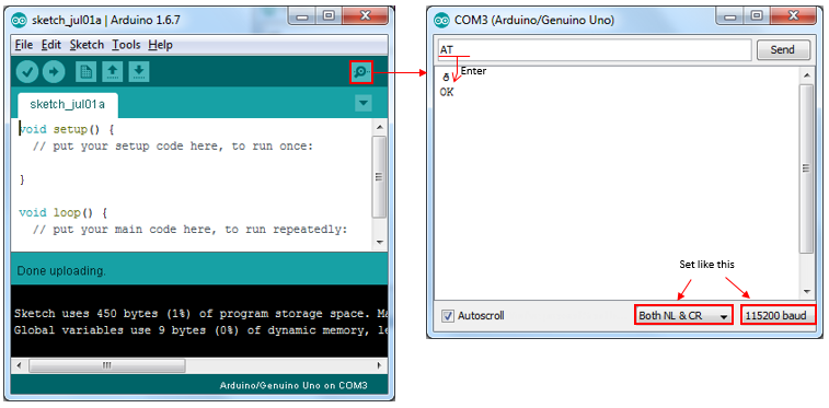
Then open the COM port monitor window and do the followings :
i) Set [Both NL & CR] as shown below
ii) Set Baud rate to be 115200 as shown below (The default baud rate of this module is 115200.)
iii) Type in 'AT' and press Enter. If you get 'OK', it means the communication between ESP8266 UART pin and Arduino UART port is working.
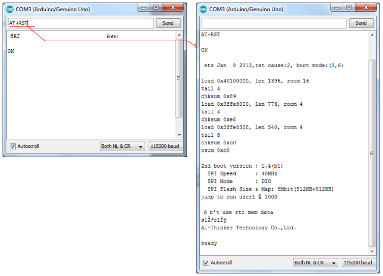
3. Initialize (Reset) the WiFi Module
Now reset the WiFi module. You don't need to do this every time. Just doing it for the first time or when you reset the device and configure everything from scratch.
Send AT+RST. If you see 'ready' at the end of the result, it indicates the reset is complete. The detailed output before 'ready' may vary depending on the module and firmware version that you are using.
4. Check the firmware version of WiFi Module
Now check the firmware version of the module using AT+GMR command. I don't guarantee all the operation here will be successful if it is too old version. (You can update the firmware with the latest version, but it will require some additional procedure which is not explained here)
Command : AT+GMR
Response :
AT version:0.40.0.0(Aug 8 2015 14:45:58)
SDK version:1.3.0
Ai-Thinker Technology Co.,Ltd.
Build:1.3.0.2 Sep 11 2015 11:48:04
OK
5. Set the device mode to make it function as both 'Client and AP (Mode 3)'.
Now set the mode of the WiFi module to be 3 as shown below.
Command : AT+CWMODE=3
Response : OK
Note : There are three different modes for ESP8266 as follows.
1 - client
2 - Access Point
3 - Client and Access Point
Now search WiFi Accesspoints available around the module. Following is an example of search result.
Command : AT+CWLAP
Response :
+CWLAP:(3,“AP_IoT1",-83,"84:a4:23:93:54:1e",1,-34)
+CWLAP:(0, “AP_IoT2",-73,"06:18:0a:31:21:fe",1,-34)
+CWLAP:(4, “AP_IoT3",-58,"f0:7f:06:bc:76:9b",1,-16)
OK
You can figure out many details of the each Access Point that are found by interpreting the result of AT+CWLAP as shown below.

7. Join onto the Access Point (Connect to AP)
Now you can join to any one of the APs that are found in previous step using AT+CWJAP command as shown below.
Command : AT+CWJAP="AP_IoT1","1234"
Response :
WIFI CONNECTED
WIFI GOT IP
OK
If the connection to the specified AP (SSID) is done properly, you would get the IP address assigned to the module when you send the command AT+CIFSR.
Command : AT+CIFSR
Response :
+CIFSR:APIP,"192.168.4.1"
+CIFSR:APMAC,"5e:cf:7f:00:2c:7f"
+CIFSR:STAIP,"192.168.0.22" // Make it sure that you got IP address assigned here.
+CIFSR:STAMAC,"5c:cf:7f:00:2c:7f"
OK
If you went through all the procedure and got proper response for those steps, the module is properly configured and connected to your WiFi network at IP level.
Command : AT+CWSAP?
Response :
+CWSAP:"AI,THINKER_3CC3E8","",6,0,4,0
10. Set AP Parameters and Connection Check
Command : AT+CWSAP="ESP8266","",6,0
Response :
OK
NOTE : AT+CWSAP command format and meaning of each parameter is as follows.
AT+CWSAP=ssid,password,channel,encryption
the number for encryption paramter is as follows
0 OPEN
2 WPA_PSK
3 WPA2_PSK
4 WPA_WPA2_PSK
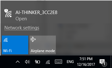
If the command is executed successfully, check if the module can be found as an AP(Access Point) with your PC. If everything is working fine, you would see the SSID from your PC or mobile phone.
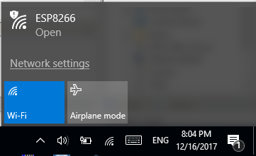
Then try Connect and see if it get connected as shown below.

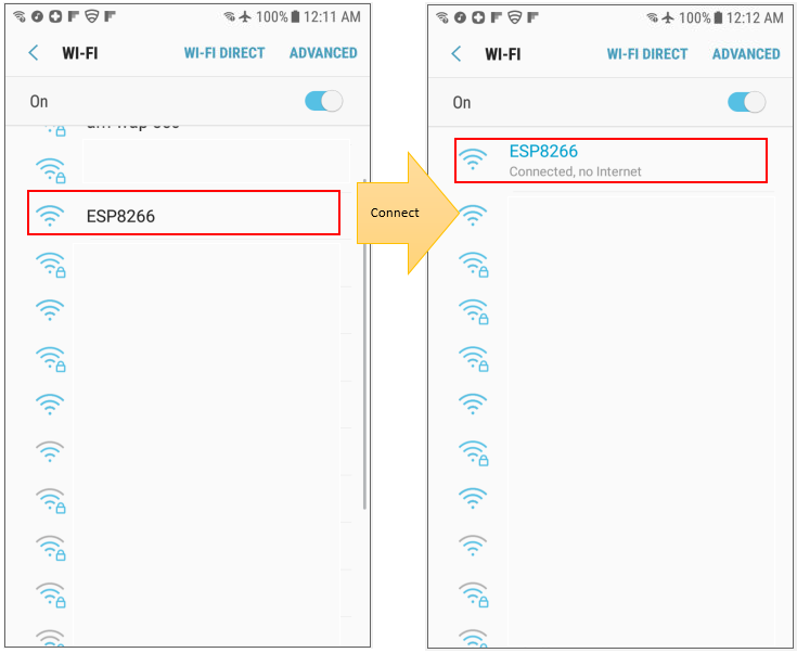
You can do same checkup with a mobile phone as shown below.
Now let's check if the module works at higher layer (higher layer than IP, e.g TCP layer). In this tutorial, we will configure the module as a TCP client and try to get access to a web server. (You don't need to have your own web server for this test because we will try to connect to a public server).
Enable the IP multiplexing capability of the module by using AT+CIPMUX command as shown below.
Command : AT+CIPMUX=1
Response :
OK
2. Establish TCP Connection to a Server
Get the module to connect to a web server using a command as follows :
Command : AT+CIPSTART=4,"TCP","www.google.com",80
Response :
4,CONNECT
OK
Note : This command would take a some time (several seconds) to establish the TCP connection to the server and give the return as shown above. In some case, you may get 'DNS fail' error. I am not sure about the exact cause of this error.. my guess is that it is because the module failed to get DNS response for the url. Probably because of too low network speed. But the exact cause is not known. Just a couple of more tries and see if you get connected.
Now send following command. This indicate 'give me the prompt to send 18 bytes of data'.
Command : AT+CIPSEND=4,18
Response :
> // The result of the command is this prompt. At this prompt, you can send whatever command
// that the server can understand.
Since the server that is connected in this tutorial is a web server, you can send a command as follows to retrieve a contents.
Command : GET / HTTP/1.0 // After sending this command, you should press [Enter] key again to retrive the
// contents from the server.
Response :
+IPD,4,471:HTTP/1.0 302 Found
Cache-Control: private
Content-Type: text/html; charset=UTF-8
Location: http://www.google.ca/?gfe_rd=cr&ei=8hV2V62kF6uC8Qeq7qagDQ
Content-Length: 258
Date: Fri, 01 Jul 2016 07:04:18 GMT
<HTML><HEAD><meta http-equiv="content-type" content="text/html;charset=utf-8">
<TITLE>302 Moved</TITLE></HEAD><BODY>
<H1>302 Moved</H1>
The document has moved
<A HREF="http://www.google.ca/?gfe_rd=cr&ei=8hV2V62kF6uC8Qeq7qagDQ">here</A>.
</BODY></HTML>
4,CLOSED
Setting up the module by Program
The example shown above is to configure the module manually by typing an AT command. However, in real application it would be more likely to configure the module automatically by Arduino program.
In this section, I will show you how to control ESP8266 module from an Arduino program. In this test, I still want to use Arduino built in Serial Port to print out the output string. So I configured other two digital ports into a software serial port and connected the module and PC as shown below. (NOTE : If you are not familiar with Softwar Serial, I would recommend you to go through Serial : Software Serial note);

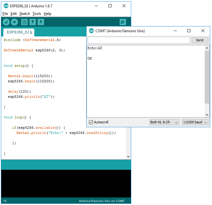
Example 01 > Forwarding AT command from PC to ESP8266 Module and Printing the response
#include <SoftwareSerial.h>
SoftwareSerial esp8266(2, 3);
void setup() {
Serial.begin(115200);
esp8266.begin(115200);
delay(100);
esp8266.println("AT");
}
void loop() {
if(esp8266.available()) {
Serial.println("Echo:" + esp8266.readString());
};
}
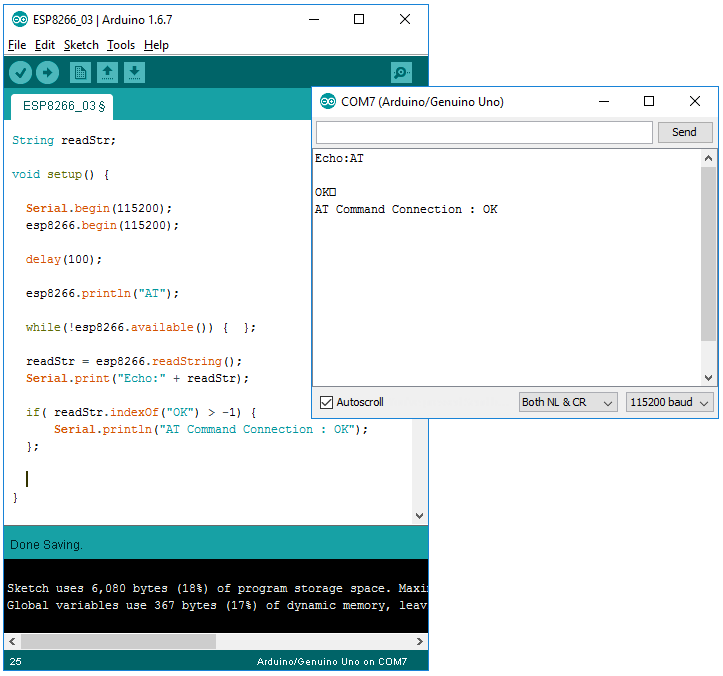
Example 02 > Forwarding AT command from PC to ESP8266 Module and Verify the result
#include <SoftwareSerial.h>
SoftwareSerial esp8266(2, 3);
String readStr;
void setup() {
Serial.begin(115200);
esp8266.begin(115200);
delay(100);
esp8266.println("AT");
while(!esp8266.available()) { };
readStr = esp8266.readString();
Serial.print("Echo:" + readStr);
if( readStr.indexOf("OK") > -1) {
Serial.println("AT Command Connection : OK");
};
}
void loop() {
}
Example 03 > Automatic Connection to a Specified AP
#include <SoftwareSerial.h>
SoftwareSerial esp8266(2, 3);
String readStr;
int incomingByte = 0; // for incoming serial data
int i = 0;
void setup() {
Serial.begin(115200);
esp8266.begin(115200);
delay(100);
esp8266_InitialSetup();
}
void loop() {
Serial.println("\n\nWaiting for User Command...\n");
while(!Serial.available()) { };
esp8266.print(Serial.readString());
while(!esp8266.available()) { };
readStr = esp8266.readString();
Serial.print(readStr);
delay(100);
readStr = esp8266.readString();
Serial.print(readStr);
}
void esp8266_InitialSetup()
{
// Check AT connection ========================================
esp8266.println("AT");
while(!esp8266.available()) { };
readStr = esp8266.readString();
Serial.print(readStr);
if( readStr.indexOf("OK") > -1) {
Serial.println("\n\rAT Command Connection : OK\n\r");
} else {
Serial.println("\n\rAT Command Connection : FAIL\n\r");
return;
};
delay(100);
// Set Device Mode ========================================
esp8266.println("AT+CWMODE=3");
while(!esp8266.available()) { };
readStr = esp8266.readString();
Serial.print(readStr);
if( readStr.indexOf("OK") > -1) {
Serial.println("\n\rSet Device Mode : OK\n\r");
};
readStr = esp8266.readString();
Serial.print(readStr);
delay(100);
// Connect to AP ========================================
for(i = 1; i <= 5; i++) {
Serial.print("Trying Connection[");
Serial.print(i,DEC);
Serial.print("]...\n\r");
esp8266.println("AT+CWJAP=\"My_TestAP\",\"********"");
while(!esp8266.available()) { };
readStr = esp8266.readString();
Serial.print(readStr + "\n");
if( readStr.indexOf("OK") > -1) {
Serial.println("\n\rAP Connection : OK\n\r");
break;
};
readStr = esp8266.readString();
Serial.print(readStr + "\n");
delay(5000);
};
delay(100);
// Set MUX ========================================
esp8266.println("AT+CIPMUX=1");
while(!esp8266.available()) { };
readStr = esp8266.readString();
Serial.print(readStr);
if( readStr.indexOf("OK") > -1) {
Serial.println("\n\rSet MUX Mode : OK\n\r");
};
readStr = esp8266.readString();
Serial.print(readStr);
// Run Internal Server ========================================
esp8266.println("AT+CIPSERVER=1,8888");
while(!esp8266.available()) { };
readStr = esp8266.readString();
Serial.print(readStr);
if( readStr.indexOf("OK") > -1) {
Serial.println("\n\rRun Internal Server : OK\n\r");
};
readStr = esp8266.readString();
Serial.print(readStr);
delay(100);
}
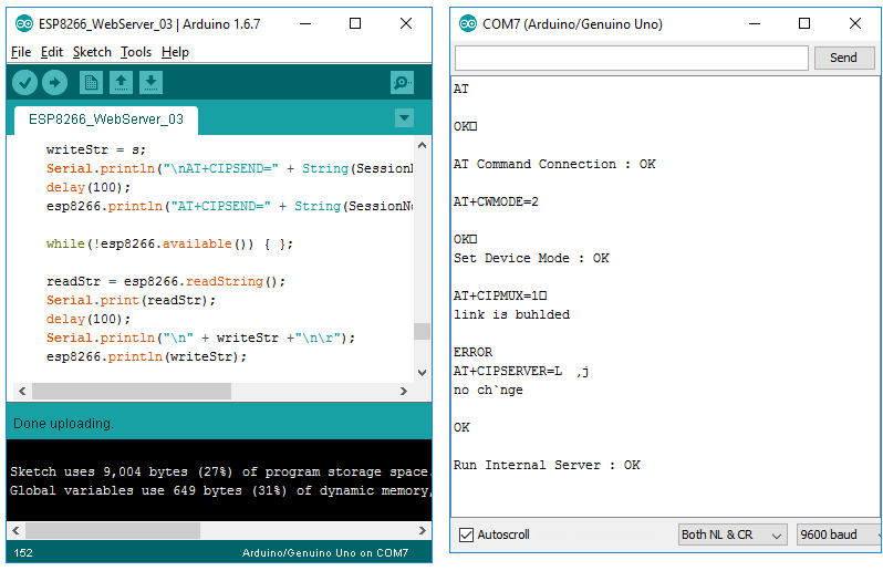
Creating a Web Server on ESP8266
ESP8622 is not a sample module like a sensor or motor. It is a kind of a system on its own (It is a kind of SoC (System On Chip)). In this example, I will show you an application that can show you a power of ESP8266 module. In addition to WiFi chip, it has its own processor on it supporting various type of functionality.
In this example, I will configure ESP8266 to work as an AP (Access Point) and run a TCP server. When user get access to the TCP server via a browser, the module will send response in the form of html format.
The connection between Arduino and ESP8266 is shown as below. In this example as well, I will use pin 2,3 as a software serial port that communicate with ESP8266.
Before you run any of the examples in this section, make it sure that you performed the procedure described in following section.
Example 01 >
#include <SoftwareSerial.h>
SoftwareSerial esp8266(2, 3);
String readStr, writeStr;
int incomingByte = 0; // for incoming serial data
int i = 0;
void setup() {
Serial.begin(9600);
esp8266.begin(115200);
delay(100);
esp8266_InitialSetup();
}
void loop() {
while(!esp8266.available()) { };
readStr = esp8266.readString();
Serial.print(readStr);
if( readStr.indexOf("HTTP") > -1) {
writeStr = "<h1>Hello World</h1>";
Serial.println("\nAT+CIPSEND=0," + String(writeStr.length()+2));
delay(100);
esp8266.println("AT+CIPSEND=0," + String(writeStr.length()+2) );
while(!esp8266.available()) { };
readStr = esp8266.readString();
Serial.print(readStr);
delay(1000);
Serial.println("\n" + writeStr +"\n\r");
esp8266.println(writeStr);
delay(3000);
};
}
void esp8266_InitialSetup()
{
// Check AT connection ========================================
esp8266.println("AT");
while(!esp8266.available()) { };
readStr = esp8266.readString();
Serial.print(readStr);
if( readStr.indexOf("OK") > -1) {
Serial.println("\n\rAT Command Connection : OK\n\r");
} else {
Serial.println("\n\rAT Command Connection : FAIL\n\r");
return;
};
delay(100);
// Set Device Mode ========================================
esp8266.println("AT+CWMODE=2");
while(!esp8266.available()) { };
readStr = esp8266.readString();
Serial.print(readStr);
if( readStr.indexOf("OK") > -1) {
Serial.println("\n\rSet Device Mode : OK\n\r");
};
readStr = esp8266.readString();
Serial.print(readStr);
delay(100);
// Set MUX ========================================
esp8266.println("AT+CIPMUX=1");
while(!esp8266.available()) { };
readStr = esp8266.readString();
Serial.print(readStr);
if( readStr.indexOf("OK") > -1) {
Serial.println("\n\rSet MUX Mode : OK\n\r");
};
readStr = esp8266.readString();
Serial.print(readStr);
// Run Internal Server ========================================
esp8266.println("AT+CIPSERVER=1,80");
while(!esp8266.available()) { };
readStr = esp8266.readString();
Serial.print(readStr);
if( readStr.indexOf("OK") > -1) {
Serial.println("\n\rRun Internal Server : OK\n\r");
};
readStr = esp8266.readString();
Serial.print(readStr);
delay(100);
}
NOTE : Followings are the description of the some of important parts (I think you would understand most of the other parts without any special explanation).
esp8266.println("AT+CIPSEND=0," + String(writeStr.length()+2) );
: This line is to send the AT command as follows
AT+CIPSEND=SessionID,Length
SessionID : Actually you would need to figure out Session ID by programming (e.g, by parsing the result of +IPD command), but for simplicity I hardcoded the session id here. If you run the module as AP only mode ("AT+CWMODE=2"), the session ID would be set as 0, however it may not always be set as 0.
Length : This indicate the length of the string to send. This should be the length of the string + 2. You need to add 2 to the length of the string because '\n\r' should be added at the end of the string (This addition is automatically done by println())
esp8266.println("AT+CIPSERVER=1,80");
: This is to run the the AT command with the following format
AT+CIPSERVER=mode[,port]
mode can be one of the follows
0: Delete server (need to follow by restart)
1: Create server
port: port number, default is 333
Example 02 >
#include <SoftwareSerial.h>
SoftwareSerial esp8266(2, 3);
String readStr, writeStr;
int incomingByte = 0; // for incoming serial data
int i = 0;
void setup() {
Serial.begin(9600);
esp8266.begin(115200);
delay(100);
esp8266_InitialSetup();
}
void loop() {
while(!esp8266.available()) { };
readStr = esp8266.readString();
Serial.print(readStr);
if( readStr.indexOf("HTTP") > -1) {
// Send the page
SendToClient(0,"<html>");
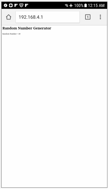
SendToClient(0,"<body>");
SendToClient(0,"<h1>Random Number Generator</h1>");
SendToClient(0,"<p>Random Number = " + String(random(300)) + "</p>");
SendToClient(0,"</body>");
SendToClient(0,"</html>");
delay(1000);
// Close the session
CloseSession(0);
delay(1000);
};
}
void esp8266_InitialSetup()
{
// Check AT connection ========================================
esp8266.println("AT");
while(!esp8266.available()) { };
readStr = esp8266.readString();
Serial.print(readStr);
if( readStr.indexOf("OK") > -1) {
Serial.println("\n\rAT Command Connection : OK\n\r");
} else {
Serial.println("\n\rAT Command Connection : FAIL\n\r");
return;
};
delay(100);
// Set Device Mode ========================================
esp8266.println("AT+CWMODE=2");
while(!esp8266.available()) { };
readStr = esp8266.readString();
Serial.print(readStr);
if( readStr.indexOf("OK") > -1) {
Serial.println("\n\rSet Device Mode : OK\n\r");
};
readStr = esp8266.readString();
Serial.print(readStr);
delay(100);
// Set MUX ========================================
esp8266.println("AT+CIPMUX=1");
while(!esp8266.available()) { };
readStr = esp8266.readString();
Serial.print(readStr);
if( readStr.indexOf("OK") > -1) {
Serial.println("\n\rSet MUX Mode : OK\n\r");
};
readStr = esp8266.readString();
Serial.print(readStr);
// Run Internal Server ========================================
esp8266.println("AT+CIPSERVER=1,80");
while(!esp8266.available()) { };
readStr = esp8266.readString();
Serial.print(readStr);
if( readStr.indexOf("OK") > -1) {
Serial.println("\n\rRun Internal Server : OK\n\r");
};
readStr = esp8266.readString();
Serial.print(readStr);
delay(100);
}
void SendToClient(int SessionNo, String s)
{
writeStr = s;
Serial.println("\nAT+CIPSEND=" + String(SessionNo) + "," + String(writeStr.length()+2));
delay(100);
esp8266.println("AT+CIPSEND=" + String(SessionNo) + "," + String(writeStr.length()+2) );
while(!esp8266.available()) { };
readStr = esp8266.readString();
Serial.print(readStr);
delay(100);
Serial.println("\n" + writeStr +"\n\r");
esp8266.println(writeStr);
return;
}
void CloseSession(int SessionNo)
{
esp8266.println("AT+CIPCLOSE=" + String(SessionNo));
while(!esp8266.available()) { };
readStr = esp8266.readString();
Serial.print(readStr);
return;
}
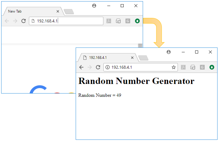
Example 03 >
#include <SoftwareSerial.h>
SoftwareSerial esp8266(2, 3);
String readStr, writeStr;
int incomingByte = 0; // for incoming serial data
int i = 0;
void setup() {
//Serial.begin(9600);
esp8266.begin(115200);
delay(100);
esp8266_InitialSetup();
}
void loop() {
while(!esp8266.available()) { };
readStr = esp8266.readString();
//Serial.print(readStr);
if( readStr.indexOf("HTTP") > -1) {
// Send the page
SendToClient(0,"<html>");
SendToClient(0,"<body>");
SendToClient(0,"<h1>Random Number Generator</h1>");
SendToClient(0,"<p>Random Number = " + String(random(300)) + "</p>");
SendToClient(0,"</body>");
SendToClient(0,"</html>");
delay(1000);
// Close the session
CloseSession(0);
delay(1000);
};
}
void esp8266_InitialSetup()
{
// Check AT connection ========================================
esp8266.println("AT");
while(!esp8266.available()) { };
readStr = esp8266.readString();
//Serial.print(readStr);
if( readStr.indexOf("OK") > -1) {
//Serial.println("\n\rAT Command Connection : OK\n\r");
} else {
//Serial.println("\n\rAT Command Connection : FAIL\n\r");
return;
};
delay(100);
// Set Device Mode ========================================
esp8266.println("AT+CWMODE=2");
while(!esp8266.available()) { };
readStr = esp8266.readString();
//Serial.print(readStr);
if( readStr.indexOf("OK") > -1) {
//Serial.println("\n\rSet Device Mode : OK\n\r");
};
readStr = esp8266.readString();
//Serial.print(readStr);
delay(100);
// Set MUX ========================================
esp8266.println("AT+CIPMUX=1");
while(!esp8266.available()) { };
readStr = esp8266.readString();
//Serial.print(readStr);
if( readStr.indexOf("OK") > -1) {
//Serial.println("\n\rSet MUX Mode : OK\n\r");
};
readStr = esp8266.readString();
//Serial.print(readStr);
// Run Internal Server ========================================
esp8266.println("AT+CIPSERVER=1,80");
while(!esp8266.available()) { };
readStr = esp8266.readString();
//Serial.print(readStr);
if( readStr.indexOf("OK") > -1) {
//Serial.println("\n\rRun Internal Server : OK\n\r");
};
readStr = esp8266.readString();
//Serial.print(readStr);
delay(100);
}
void SendToClient(int SessionNo, String s)
{
writeStr = s;
//Serial.println("\nAT+CIPSEND=" + String(SessionNo) + "," + String(writeStr.length()+2));
delay(100);
esp8266.println("AT+CIPSEND=" + String(SessionNo) + "," + String(writeStr.length()+2) );
while(!esp8266.available()) { };
readStr = esp8266.readString();
//Serial.print(readStr);
delay(100);
//Serial.println("\n" + writeStr +"\n\r");
esp8266.println(writeStr);
return;
}
void CloseSession(int SessionNo)
{
esp8266.println("AT+CIPCLOSE=" + String(SessionNo));
while(!esp8266.available()) { };
readStr = esp8266.readString();
//Serial.print(readStr);
return;
}
Reference
[2] ESP8266 Setup Tutorial using Arduino
[3] How To Use the ESP8266 and Arduino as a Webserver
[4] ESP8266 Serial WIFI Module
[5] ESP8266 Firmware Update with Arduino Board
[6] NURDs : ESP8266 AT Commands
[7] espressif/ESP8266_AT/HOME (GitHub)
[8] Server-Client Communication using ESP8266 Serial WiFi Module (ESP-01)
[9] ESP8266 - Easiest way to program so far (Using Arduino IDE)
[10] Simple Webserver Using Arduino and ESP8266