A convolutional encoder is a small piece of hardware, and this page is mostly about four ways of drawing that same piece of hardware. The encoder used throughout takes one bit in, puts two bits out, and holds two bits of memory. Every diagram below describes that one machine.
- What is convolution code ?
- How to represent it ?
- Shift Register
- State Diagram
- Trellis Diagram
- Polynomial
- Encoding Example
- Decoding - Assuming No Error
- YouTube
What is convolution code ?
Convolution Code is a type of channel coding that generate two bits of coded bits out of one input bit. The name convolution code comes from the way in which how each of the two output bits are generated. Mathematically they are generated by the mathematical opeartion of convolution as shown below.

- The block takes one input bit x(i) and produces two output bits, labelled first bit of output and second bit of output.
- The first is C0(i), a sum over k of h(k) x(i-k). The second is C1(i), the same sum with g(k) in place of h(k).
- h and g are two different generator sequences, and they are what makes the two outputs differ, because the same input history runs through both.
- The note at the upper right gives the reason for the word convolutional. Both expressions have the form of a convolution sum.
Two things follow from those sums, and both matter later. The index runs over x(i-k) rather than over x(i) alone, so each output bit depends on a window of past input bits rather than on the present one only. The upper limit n fixes how far back that window reaches, and it sets how many memory elements the encoder needs.
The code rate follows directly. One bit enters and two leave, so this encoder has rate 1/2. Nothing in the construction forces that ratio. Other encoders produce three or more output bits per input bit, but every diagram on this page uses rate 1/2.
How to represent it ?
There can be many different ways to represent the process for convolutional code.. but I think following three methods are the most common representation you would see in any materials about encoding/decoding process.
- Shift Register
- State Diagram
- Trellis Diagram
The three show the same encoder from different angles. The shift register shows the hardware, so it answers what the encoder is built from. The state diagram keeps only the memory contents and the moves between them, so it answers where the encoder can go next. The trellis diagram draws those same moves against time, so it answers which path the encoder actually took.
A fourth notation arrives later, under Polynomial. That one is not a picture at all but a pair of numbers, and it is the form that specifications and software use to name an encoder. Reading it needs the shift register view first, which is why it comes after the three.
What would be the common things to all of these methods ? It is damm difficult and confusing -:)
The examples shown here are the simplest thing. I am almost 100% sure that I would have difficulties understanding these diagrams at first look... do it again ... do it again ... eventually understand ... and get confused again .... do get disappointed about yourself if you have the same difficulties.
Don't try memorizing these illustrations(examples). Try to cleary understand once. No problem with forgetting. Just come back to these examples again whenever you need it. If it takes a couple of hours to understand these examples for the first time, it would take only a couple of minutes when you revisit here.
Shift Register
Shift Register representation is closest form of physical implemenation of the encoder and this would be the best representation if you are a hardware (or FPGA) designer. But it would be very difficult to figure out the output bit stream if you have to get them from drawing. Only two bit shift register gives you the very complicated process of interpretation as shown below. So if the number of shift register is very high, it would be almost impossible for you to figure out the output bit stream by drawing.
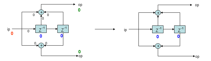
a) Answer following questions for the illustration.
What is the current status (Values in shift register) ? --> 00 (The diagram on the left - Blue)
What is the input value ? --> 0 (The diagram on the left - Red)
What is the output value ? --> 00 (The diagram on the left - Green)
What is the next status (Values in shift register after encoding) ? --> 00 (The diagram on the right - Blue)
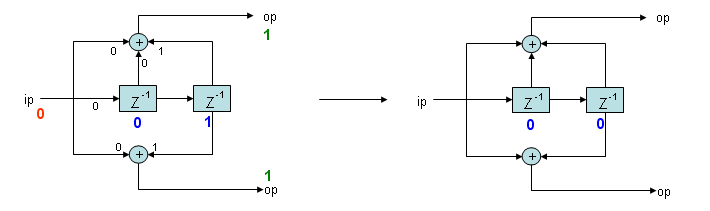
b) Answer following questions for the illustration.
What is the current status (Values in shift register) ? --> 01 (The diagram on the left - Blue)
What is the input value ? --> 0 (The diagram on the left - Red)
What is the output value ? --> 11 (The diagram on the left - Green)
What is the next status (Values in shift register after encoding) ? --> 00 (The diagram on the right - Blue)
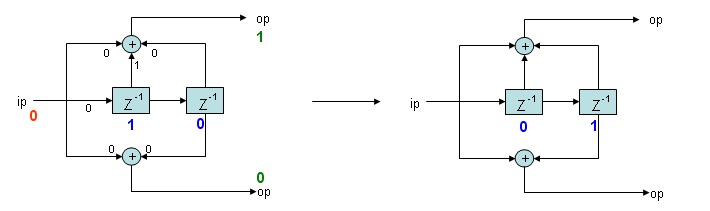
c) Answer following questions for the illustration.
What is the current status (Values in shift register) ? --> 10 (The diagram on the left - Blue)
What is the input value ? --> 0 (The diagram on the left - Red)
What is the output value ? --> 10 (The diagram on the left - Green)
What is the next status (Values in shift register after encoding) ? --> 01 (The diagram on the right - Blue)
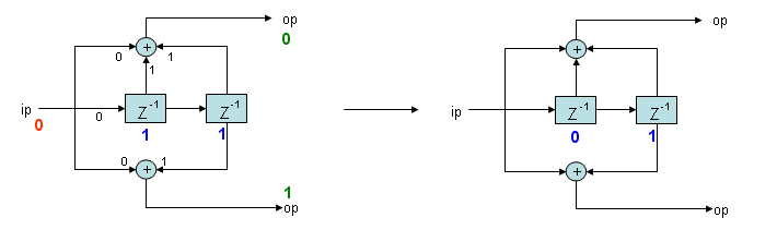
d) Answer following questions for the illustration.
What is the current status (Values in shift register) ? --> 11 (The diagram on the left - Blue)
What is the input value ? --> 0 (The diagram on the left - Red)
What is the output value ? --> 01 (The diagram on the left - Green)
What is the next status (Values in shift register after encoding) ? --> 01 (The diagram on the right - Blue)
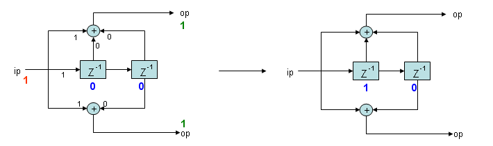
e) Answer following questions for the illustration.
What is the current status (Values in shift register) ? --> 00 (The diagram on the left - Blue)
What is the input value ? --> 1 (The diagram on the left - Red)
What is the output value ? --> 11 (The diagram on the left - Green)
What is the next status (Values in shift register after encoding) ? --> 10 (The diagram on the right - Blue)
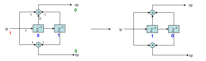
f) Answer following questions for the illustration.
What is the current status (Values in shift register) ? --> 01 (The diagram on the left - Blue)
What is the input value ? --> 1 (The diagram on the left - Red)
What is the output value ? --> 00 (The diagram on the left - Green)
What is the next status (Values in shift register after encoding) ? --> 10 (The diagram on the right - Blue)
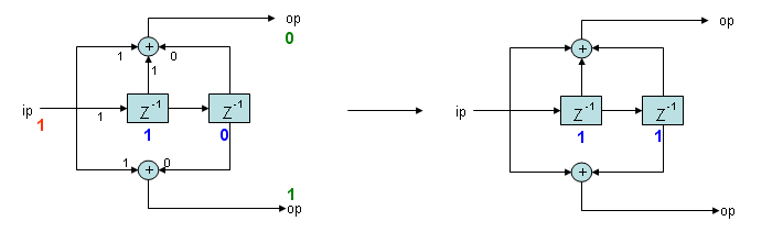
g) Answer following questions for the illustration.
What is the current status (Values in shift register) ? --> 10 (The diagram on the left - Blue)
What is the input value ? --> 1 (The diagram on the left - Red)
What is the output value ? --> 01 (The diagram on the left - Green)
What is the next status (Values in shift register after encoding) ? --> 11 (The diagram on the right - Blue)
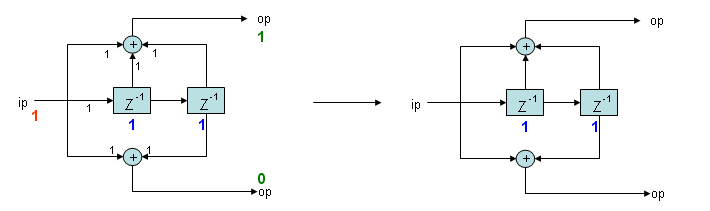
h) Answer following questions for the illustration.
What is the current status (Values in shift register) ? --> 11 (The diagram on the left - Blue)
What is the input value ? --> 1 (The diagram on the left - Red)
What is the output value ? --> 10 (The diagram on the left - Green)
What is the next status (Values in shift register after encoding) ? --> 11 (The diagram on the right - Blue)
State Diagram
The shift register above shows what the encoder contains. The state diagram throws that detail away and keeps one thing, which is the pair of bits held in memory. Four states are possible, and every input bit moves the encoder from one of them to another.
Following two are the same encoding process. (The description is transition a) in previous section)
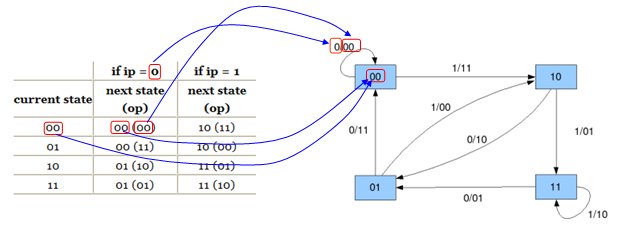
- The table on the left gives, for each current state, the next state with the output bits in brackets, once for input 0 and once for input 1.
- The highlighted row is current state 00 with input 0. The next state is 00 and the output is 00.
- In the diagram on the right that row is the self loop on state 00, labelled 0/00. Each label reads input over output.
- The shift register beside it shows the same move. Both memory cells hold 0, the input is 0, and both adders therefore produce 0.
Following two are the same encoding process. (The description is transition e) in previous section)
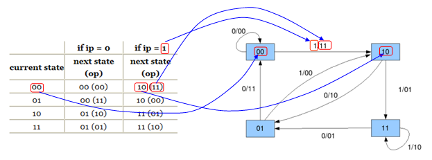
- The highlighted row is now current state 00 with input 1. The next state is 10 and the output is 11.
- In the diagram that row is the arrow from 00 to 10, labelled 1/11.
- The shift register shows why. The input 1 reaches both adders directly, so both outputs are 1, and after the shift the first memory cell holds that 1, which is the state 10.
Two points matter later. The state is the memory contents and nothing else, so an encoder with two memory cells has exactly four states. Each state also has exactly two arrows leaving it, one per input bit, and the trellis diagram below depends on that.
Trellis Diagram
At least to me, Trellis Diagram is the most complicated presentation camparing the other two representation we saw above. But once I understand the logic, I found it so useful way of presentation.
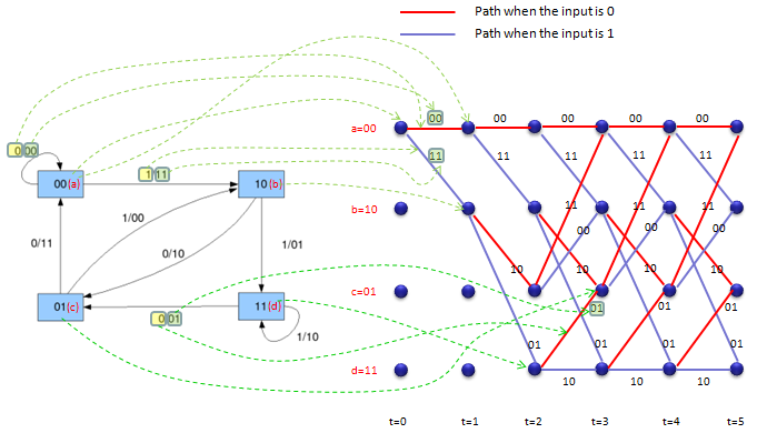
Basically Trellis Diagram is made up of matrix of nodes (Blue filled circle shown below). Each of the nodes represents each status in the status diagram. Each column of the nodes represents all the possible status at a certain time. For example, the first column (the leftmost colum represents all the possible status at the initial status (t = 0) of the statemachine. The second column represents all th possible status when t = 1. The third column represents all th possible status when t = 2 and so on.
Each of the nodes can have two possible path to move to next status. One path is the transition path when the input bit is 0 and the other path is the transition path when the input bit is 1. The path when the input bit = 0 is marked in red line and the path when the input bit = 1 is marked in blue line.
If the statemachine starts with '00', all the possible state transition can be represented as below. Follow each of green arrows (dotted lines) and trying to assosicate the statemachine and Trellis diagram.
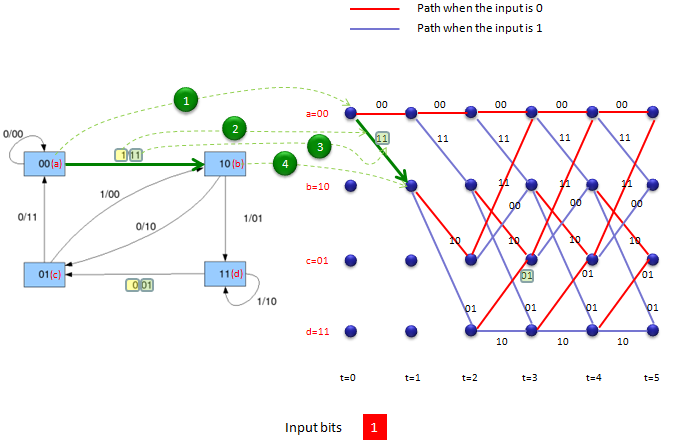
To represent the process in simpler way, let's take an example of the first single transition.
I will explain the steps of interpretation in Q & A form. I assume that the state machine is at t = 0 (initial status) and the status bits are '00'.
i) What is the current status bit ? --> 00 (follow the green line marked as (1))
ii) What is the input bit ? --> '1' (Input bit at t = 0 is given as '1' shown at the bottom in red rectangle).
iii) There are two path coming out of '00' status. Which path we have to follow ? --> Follow the path marked in green arrow.(follow the green line marked as (2))
iv) What is the output of this transition --> 11.(follow the green line marked as (3))
v) What is the next status ? --> 10(follow the green line marked as (4))
Follow these steps several times until you clearly understand the procedure before you go next.
Polynomial
In previous sections, we saw several different ways to represent a same entity ('Convolutional encoder') and you would have seen those representation in the most of digital communication text books. But if you look for the encoder description in various technical specification(for example, 3GPP specification 36.212 5.1.3 Channel Coding), you would see the encoders represented in the form of polynomials. At first glance, it would be hard to grasp the meaning out of those polynomials, but it is very handy way of expression because it is simple and probably more importantly it can be analyzed by many mathematical techniques.
The first thing you need to understand the meaning of a polynomial is to understand how each term of the polynomial is related to each component of shift register representation. Do practice of this kind of conversion until your brain automatically draw the pictures when you see a set of polynomial.
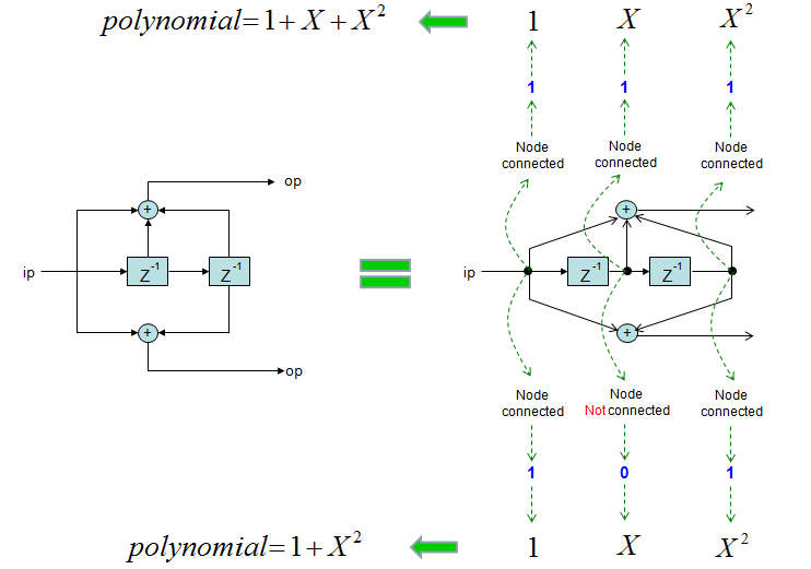
- The encoder on the left is the one used throughout this page, drawn without labels.
- On the right the same encoder is redrawn with a tap above and below each stage, and every tap is marked either node connected or not connected.
- The upper adder takes the input, the first register and the second register, so all three taps are connected. The coefficients read 1, 1, 1 and the polynomial is 1 + X + X2.
- The lower adder skips the middle tap, so the coefficients read 1, 0, 1 and the polynomial is 1 + X2.
- The power of X counts delay stages. The constant term is the undelayed input, X is one stage back, and X2 is two stages back.
In addition to polynomials, there are a couple of parameters you need to know to understand various text and software (e.g, Matlab). Try to remember the meaning of the following terms.
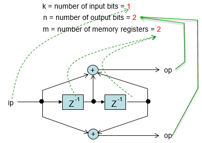
The three parameters in the drawing above are the ones that software asks for. Here k = 1, n = 2 and m = 2, so one bit enters, two leave, and two memory registers hold the history. Matlab names each polynomial in octal, reading its coefficients as binary digits. So 1 + X + X2 becomes 111 and then 7, while 1 + X2 becomes 101 and then 5. The pair 7 and 5 with constraint length 3 is the encoder every diagram on this page uses.
Encoding Example
Applying the procedures explained above, let's take an example when we have input bit stream '11010' going into the encoder. The output bit stream become '1101010010'. This encoding process can be illustrated as shown below. This is the one of the simplest example of trellis diagram for the simplest encoder (only two shift register). So make it sure that you clearly understand this example.
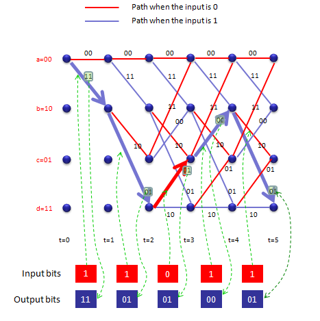
This example assumes that the state start with 'a=00'.
Step 1 :
Current status : a = 00
Encoding Rule : 0 --> 00, 1 --> 11
Input to the status : 1 (1 bit)
Output bit (according to Econding Rule) : 11 (2 bits)
Output Status : b = 10
Step 2 :
Current status : b = 10 (The result of Previous Step)
Encoding Rule : 0 --> 10, 1 --> 01
Input to the status : 1 (1 bit)
Output (according to Econding Rule) : 01 (2 bits)
Output Status : d = 11
Step 3 :
Current status : d = 11 (The result of Previous Step)
Encoding Rule : 0 --> 01, 1 --> 10
Input to the status : 0 (1 bit)
Output (according to Econding Rule) : 01 (2 bits)
Output Status : c = 01
Step 4 :
Current status : c = 01 (The result of Previous Step)
Encoding Rule : 0 --> 11, 1 --> 00
Input to the status : 1 (1 bit)
Output (according to Econding Rule) : 00 (2 bits)
Output Status : b = 10
Step 5 :
Current status : c = 10 (The result of Previous Step)
Encoding Rule : 0 --> 10, 1 --> 01
Input to the status : 1 (1 bit)
Output (according to Econding Rule) : 01 (2 bits)
Output Status : d = 01
Econded Bits : Just concatenate output bits of all steps = 1101010001
NOTE : You can find the same example done by Matlab here.
Decoding - Assuming No Error
This is a kind of imaginary situation that is meant for principles of basic decoding. Unless it is not guaranteed that there is no error in received data, this method (deterministic decoding) would not work. Of course, in real communication we cannot guarantee that there is no error. Actually we wouldn't need this kind of encoding/decoding process at all if we can guarantee that there is no error.
Then why I talk about anything that is not used in reality ? It is because I think it would help with understanding the decoding process which is more realistic but more complex. This realistic decoding process will be posted later.
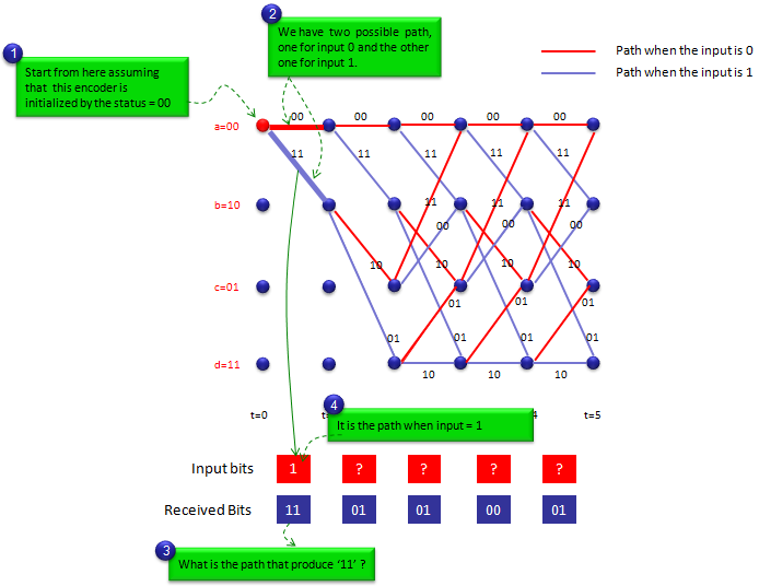
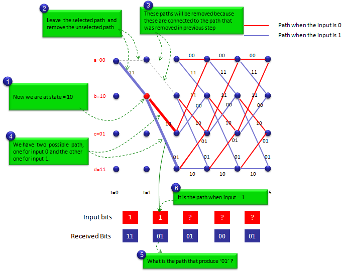
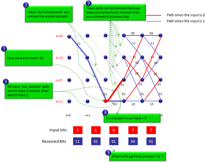
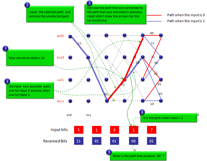
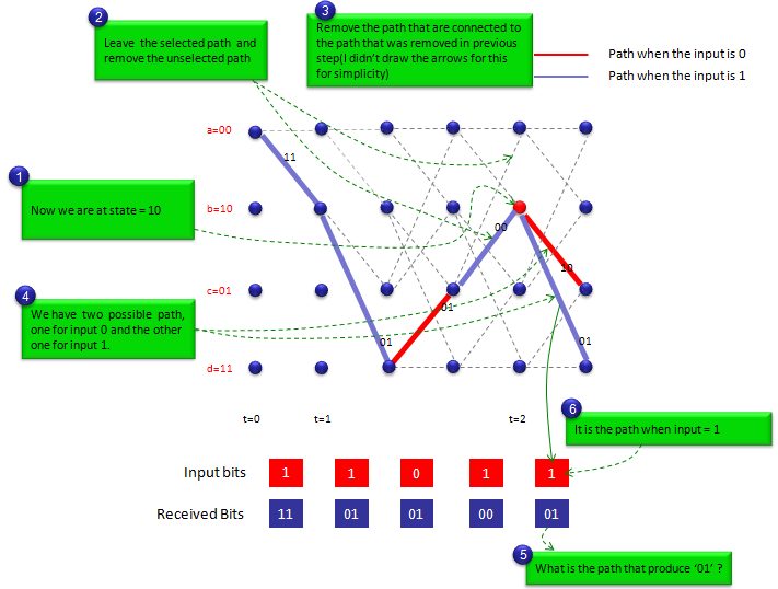
Let's assume that we have received a bit stream '1101010001' and want to decode this to get the original data (the data before encoding). Assuming that we have used 2 bit encoder, we split the received bit stream into multiple groups of two bits. Then we have 11 01 01 00 01. Now we have to do is to back track the trellis diagram to figure out the input bit stream that would have produced 11 01 01 00 01. This process would never been clearly described without using illustration and it would never been understood clearly without patiently follow step by step. If you skip even a single step, you would get confused and lose the whole track.
YouTube
[1] Lec 49 | Principles of Communication-II | Introduction to Convolutional Codes| IIT Kanpur
[2] Lec 50 | Principles of Communication-II | Example of Convolutional Code Output| IIT Kanpur
[3] Lec 51 | Principles of Communication-II | Matrix Representation of Convolutional Codes| IIT Kanpur
[4] Lec 52 | Principles of Communication-II |State Diagram representation Convolutional Code| IIT Kanpur
[5] Lec 53 | Principles of Communication-II |Trellis Representation of Convolutional Code| IIT Kanpur
[6] Lec 54 | Principles of Communication-II | Decoding of the Convolutional Code| IIT Kanpur
[7] Lec 55 | Principles of Communication-II | Principle of Decoding of Convolutional code| IIT Kanpur
[8] Lec 56 | Principles of Communication-II | Viterbi Decoder for Convolutional Code| IIT Kanpur