The list below is the short answer to most questions about LTE downlink timing. Each line is a figure worth remembering. The sections after it show where each one comes from, and several lines mark where LTE and NR agree.
|
LTE DL Frame Structure in Detail
One good way to study this kind of thing and get some practical understanding would be to start from the view from the highest level and get deeper into it step by step.
- LTE DL Frame Structure in a Nutshell
- LTE DL Frame Structure in Detail
- Overview - FDD : Frame Structure Type 1
- Overview-TDD : Frame Structure Type 2
- Overview-LAA : Frame Structure Type 3
- Physical Channels and Signals in Radio Frame
- Whole Frame Snapshot
- Physical Channels in Communication
- Gallery
- Reference
Overview - FDD : Frame Structure Type 1
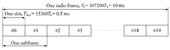
The highest level view from 36.211 for FDD LTE is as follows. It only shows the structure of one frame in time domain. It does not show any structure in frequency domain.
Some of high level description you can get from this figure would be
i) Time duration for one frame (One radio frame, One system frame) is 10 ms. This means that we have 100 radio frame per second.
ii) the number of samples in one frame (10 ms) is 307200 (307.200 K) samples. This means that the number of samples per second is 307200 x 100 = 30.72 M samples.
iii) Number of subframe in one frame is 10.
iv) Number of slots in one subframe is 2. This means that we have 20 slots within one frame.
< 36.211 Figure 4.1-1 : Frame Structure type 1 >
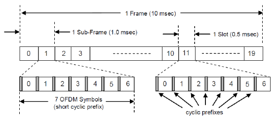
So one slot is the smallest structure in time domain ? No, if you magnify this frame structure one step further, you would get the following figure.
Now you see that one slot is made up of 7 small blocks called 'symbol'. (One symbol is a certain time span of signal that carry one spot in the I/Q constellation.).
And you see even smaller structures within a symbol. At the beginning of symbol you see a very small span called 'Cyclic Prefix' and the remaining part is the real symbol data.
There are two different type of Cyclic Prefix. One is normal Cyclic Prefix and the other is 'Extended Cyclic Prefix' which is longer than the Normal Cyclic Prefix. (Since the length of one slot is fixed and cannot be changed, if we use 'Extended Cyclic Prefix', the number of symbols that can be accomodated within a slot should be decreased. So we can have only 6 symbols if we use 'Extended Cyclic Prefix').
If you magnify a subframe to show the exact timing and samples, it can be illustrated as below. The length shown in this illustration does not vary with the Sampling Rate, but the number of samples in each symbol and CP varies with the sampling rate. The number of samples shown in this illustration is based on the case of 30.72 Mhz sampling rate.
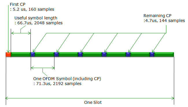
A couple of things to be noticed about the subframe structure illustrated above is
-
the first OFDM symbol within a slot is a little bit longer than the other OFDM symbols
-
the number of samples shown in this illustration is based on the assumption that the sampling rate is 30.72 M samples/sec and 2048 bins/IFFT(N_ifft). Real sampling rate and N_ifft may vary depending on system BW, you need to scale this number according to a specific BW. (or you may implement the hardware sampling at the same rate regardless of bandwidth (e.g, 30.72 Mhz sampling) and decimate the samples to the rate corresponding to each bandwidth after decoding MIBs. Actually this is more practical since you don't know the system bandwidth until you decode MIB.)
-
Typical N_ifft for each system BW is as follows
|
System BW |
Number of RBs |
N IFFT (bins/IFFT) |
|
1.4 |
6 |
128 |
|
3.0 |
15 |
256 |
|
5.0 |
25 |
512 |
|
10.0 |
50 |
1024 |
|
15.0 |
75 |
2048 |
|
20.0 |
100 |
2048 |
Following shows the overal subframe structure from "LTE Resource Grid" (I realized that this site is not available any more. Fortunately, recently another expert put great effort to create another resource grid application and allowed me to share with everybody. Here goes Sandesh Dhagle's Resource Grid)
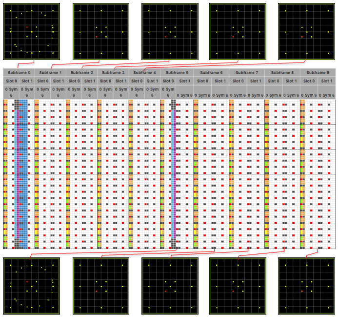
Following is an example of Downlink Frame Structure and RE (Resource Element) mapping for 4 Antenna case. Actually this is an ideal case of showing all 4 Antenna's signal super-imposed (overlapped). In reality, the signal from each antenna has a little different symbol data and reference signal position. The constellation shown on top and at the bottom of the RE mapping is the measurement result from LTE signal Analyzer measuring the LTE signal coming out of the LTE network simulator. This was captured at Antenna port 0 while LTE network is transmitting MIB/SIBs and UE is not connected. If you do the similar thing with different channel power (e.g, PCFICH power, PDCCH Power, CRS Power etc) you may see a little bit different constellation.
< FDD LTE Frame Structure with Constellation >
Now let's magnify the structure even further, but this time expand in frequency domain, not in time domain. You will get the following full detail diagram.
< FDD LTE Frame Structure with Focus On Physical Channels >
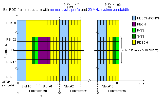
The first thing you have to be very familiar with as an engineer working on LTE is the following channel map shown above.
We can represent an LTE signal in a two dimensional map as shown above. The horizontal axis is time domain and the vertical axis is frequency domain. The minimum unit on vertical axis is a sub carrier and the minimum unit on horizontal axis is symbol. For both time domain and frequency domain, there are multiple hiarachies of the units, meaning a multiple combination of a smaller unit become a larger units.
Let's look at the frequency domain structure first.
LTE (any OFDM/OFDMA) band is made up of multiple small spaced channels and we call each of these small channels as "Sub Carrier".
Space between the chhanel and the next channel is always same regardless of the system bandwidth of the LTE band.
So if the system bandwidth of LTE channel changes, number of the channels (sub carriers) changes but the space between channels does not change.
Q> What is the space between a subcarrier and the next sub carrier ? A> 15 Khz
Q> What is the number of channels(sub carriers) for 20 Mhz LTE band ? A> 1200 sub carriers.
Q> What is the number of channels(sub carriers) for 10 Mhz LTE band ? A> 600 sub carriers.
Q> What is the number of channels(sub carriers) for 5 Mhz LTE band ? A> 300 sub carriers.
Got any feelings about sub carriers and it's relation to system bandwidth ?
Now let's look at the basic units of horizontal axis which is time domain. The minimum unit of the time domain is a Symbol, which amounts to 66.7 us. Regardless of bandwidth, the symbol length does not changes.In case of time domain, we have a couple of other structures as well. The largest unit in time domain is a frame, each of which is 10 ms in length. Each of the frame consists of 10 sub frames, each of which is 1 ms in length. Each of sub frame consists of 2 slots, each of which is 0.5 ms in length.Each of slots consists of 7 symbols, each of which is 66.7 us.
With this in mind, let's think about the scale in reverse direction.
Q> How many symbols are there in a slot ? A> 7 symbols.
Q> How many symbols in a sub frame ? A> 14 symbols.
Q> How many slots are there in a frame ? A> 20 slots.
Now let's look at the units which is made up of both time domain (horizontal axis) and frequency domain (vertical axis). Let's call this type of unit a two-dimensional unit.
The minimum two dimensional unit is resource element which is made up of one symbol in time domain and one sub carrier in frequency domain. Another two dimensional unit is resource block(RB) which is made up of one slot in time domain and 12 sub-carrier in frequency domain. Resource Block(RB) is the most important units in LTE both for protocol side and RF measurement side.
Now here goes questions.
Q> How many symbols in a resource block ? A> 7 symbols.
Q> How many sub-carriers in a resource block ? A> 12 sub-carriers.
Q> How many resource elements in a resource block ? A> 84 resource elements.
Now it's time to combine all the units we covered. The following questions are very important to read any of the LTE specification.
Q> How many resource blocks in a 20 Mhz band ? A> 100 resource blocks.
Q> How many resource blocks in a 10 Mhz band ? A> 50 resource blocks.
Q> How many resource blocks in a 5 Mhz band ? A> 25 resource blocks.
I have seen this type of mapping so many times from so many different sources, but do I really understand all the details of the map ? No not yet. It will take several years to understand every aspects of the map.
Probably what I do as the first step is to describe each part of the map in a verbal form
Overview-TDD : Frame Structure Type 2
TDD gives the uplink and the downlink the same carrier. It separates them in time instead. A radio frame therefore has to say which subframes carry which direction. One configuration number settles that for the whole frame.
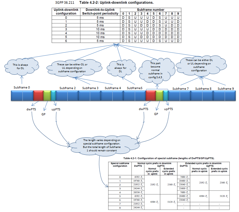
36.211 Table 4.2-2 is reproduced in the picture above, and it holds all seven configurations. A D marks a subframe reserved for downlink. A U marks one reserved for uplink. An S marks the special subframe, where the turnaround happens.
Two of the ten are fixed. Subframe 0 and subframe 5 are always downlink. The synchronization signals and the broadcast channel sit in them, and a UE has to find those before it knows the configuration.
The switch-point periodicity column splits the seven into two groups. Configurations 0, 1, 2 and 6 turn around every 5 ms, so a special subframe appears in each half-frame. Configurations 3, 4 and 5 turn around every 10 ms. Only the first half-frame then carries one, and subframe 6 becomes an ordinary downlink subframe.
The seven differ in how much uplink each one gives. Configuration 0 has six uplink subframes and configuration 5 has one, with the rest in between. The choice is a direct trade of uplink against downlink capacity.
One number fixes the whole frame : the configuration decides the direction of all ten subframes, and 36.211 allows seven of them.Subframe 0 and subframe 5 are always downlink : the synchronization signals and PBCH live there, so they cannot move.The periodicity decides the number of special subframes : 5 ms gives one in each half-frame, 10 ms gives one in the frame.The choice is a capacity trade : six uplink subframes at one end and one at the other.
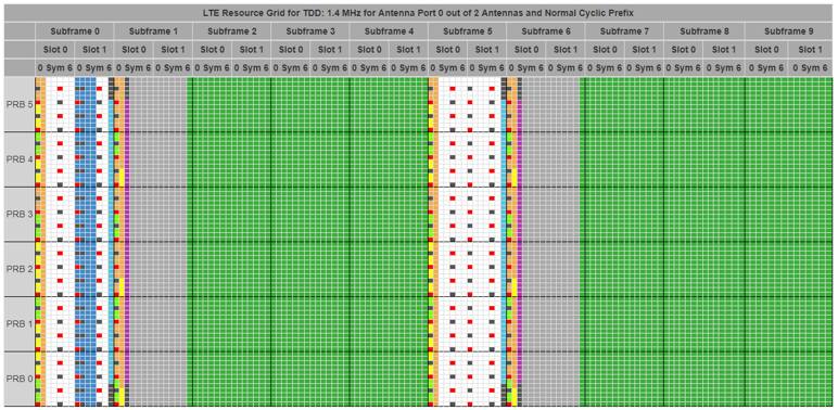
Followings are examples for various TDD UL/DL configurations. I got all of the following examples using Sandesh Dhagle's Resource Grid.
< TDD UL/DLConfiguration 0, Special Subframe Config 0 >
< TDD UL/DLConfiguration 1, Special Subframe Config 0 >
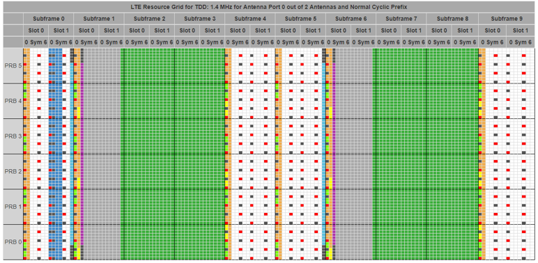
< TDD UL/DLConfiguration 2, Special Subframe Config 0 >
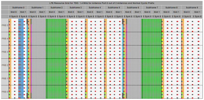
< TDD UL/DLConfiguration 3, Special Subframe Config 0 >
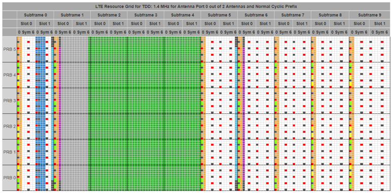
< TDD UL/DLConfiguration 4, Special Subframe Config 0 >
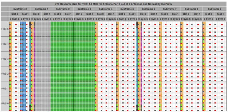
< TDD UL/DLConfiguration 5, Special Subframe Config 0 >
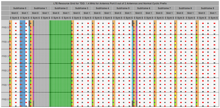
< TDD UL/DLConfiguration 6, Special Subframe Config 0 >
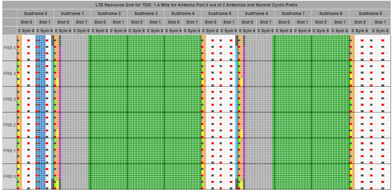
The seven grids above are coloured the same way. A green subframe is uplink. A white subframe is downlink, and the reference signal pattern shows in it. The grey block is the guard period inside a special subframe.
Counting the green columns reproduces the table exactly. Configuration 1 shows subframes 2, 3, 7 and 8 in green, which is where its row has a U. Configuration 5 shows only subframe 2.
The 10 ms configurations look different. Configurations 3, 4 and 5 carry one grey block rather than two, because their second half-frame never turns around.
Followings are the examples showing the radio resource grid with different Special Subframe Configuration. In these examples, just pay attention to how the symbol structure in subframe 0 and subframe 6 varies.
< TDD UL/DLConfiguration 0, Special Subframe Config 0 >
< TDD UL/DLConfiguration 0, Special Subframe Config 1 >
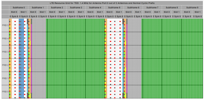
< TDD UL/DLConfiguration 0, Special Subframe Config 2 >
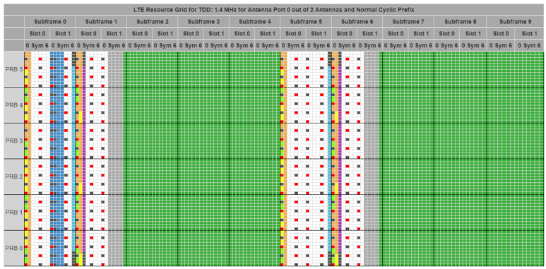
< TDD UL/DLConfiguration 0, Special Subframe Config 3 >
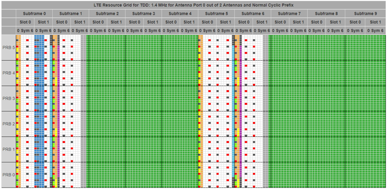
< TDD UL/DLConfiguration 0, Special Subframe Config 4 >
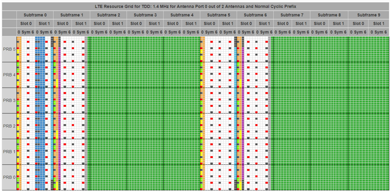
< TDD UL/DLConfiguration 0, Special Subframe Config 5 >
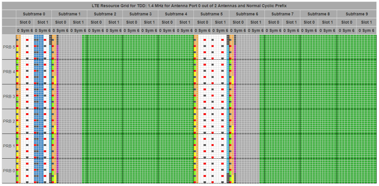
< TDD UL/DLConfiguration 0, Special Subframe Config 6 >
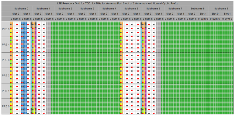
< TDD UL/DLConfiguration 0, Special Subframe Config 7 >
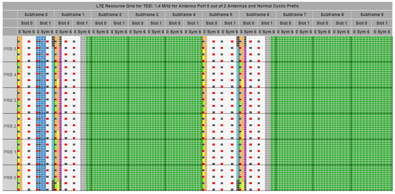
< TDD UL/DLConfiguration 0, Special Subframe Config 8 >
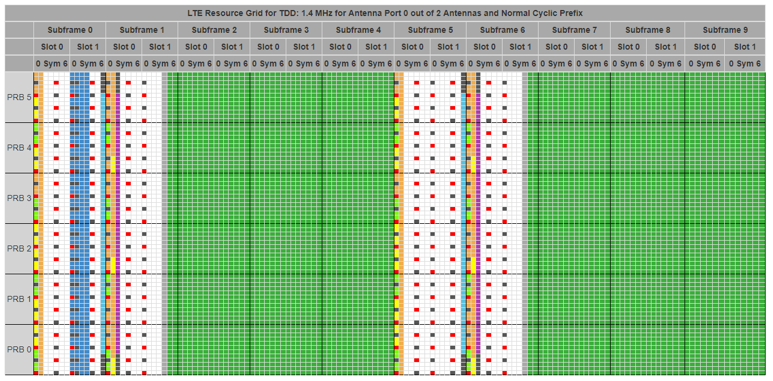
The nine grids above hold the configuration at 0. They step the special subframe configuration from 0 to 8. Only subframe 1 changes, and it is worth watching one field at a time.
Subframe 1 has three fields. DwPTS comes first and is downlink. The guard period follows and carries nothing. UpPTS ends the subframe and is uplink. Table 4.2-1 sets the first and the last, and the guard period takes what is left.
The total never changes. DwPTS grows from configuration 0 to configuration 4. The guard period shrinks by the same amount, and subframe 1 is still 1 ms long. The annotation in the picture further up this section makes the same point.
Configuration 5 starts the sequence again rather than continuing it. Its DwPTS matches configuration 0 again. What changed is UpPTS, which is now two symbols instead of one. Configurations 5 to 8 repeat the DwPTS lengths of 0 to 3 with that longer UpPTS.
The guard period is why any of this is adjustable. It covers the round trip to the edge of the cell, and the time the radio needs to switch direction. A large cell therefore takes a short DwPTS, and a small cell can use a long one.
Only subframe 1 changes across the nine grids : the configuration is held at 0, so the rest of the frame is fixed.Three fields share a fixed 1 ms : Table 4.2-1 sets DwPTS and UpPTS, and the guard period takes the remainder.The sequence starts again at configuration 5 : configurations 5 to 8 repeat the DwPTS lengths of 0 to 3 with a longer UpPTS.The guard period limits the cell radius : it covers the round trip to the cell edge, so a large cell gives up downlink symbols.
Overview-LAA : Frame Structure Type 3
From 3GPP Rel 13, a new frame structure (Frame Structure Type 3) and major application of this type is LAA. I don't find much details on this as of 36.211 V13.1.0. Following description is all for now. I think the green part is same as the existing frame type (Type 1 / Type 2) and the blue part is unique to Type 3.
Frame structure type 3 is applicable to LAA secondary cell operation with normal cyclic prefix only. Each radio frame is Tf = 307200⋅Ts =10ms long and consists of 20 slots of lengthTslot = 15360⋅Ts = 0.5 ms , numbered from 0 to 19. A subframe is defined as two consecutive slots where subframe i consists of slots 2i and 2i +1 .
The 10 subframes within a radio frame are available for downlink transmissions. Downlink transmissions occupy one or more consecutive subframes, starting anywhere within a subframe and ending with the last subframe either fully occupied or following one of the DwPTS durations in Table 4.2-1.
Another differences in Rel 13 is in following table. As you see here, in Rel 13 the length of UpPTS became parameterized (become a variable). If you set X = 0, the table is indentical to Frame type 2 case. I think X would get different values in Frame Type 3, but I haven't found any details about the value range of this parameter X yet (I will update as I find more information).
< 36.211 Table 4.2-1: Configuration of special subframe (lengths of DwPTS/GP/UpPTS) >
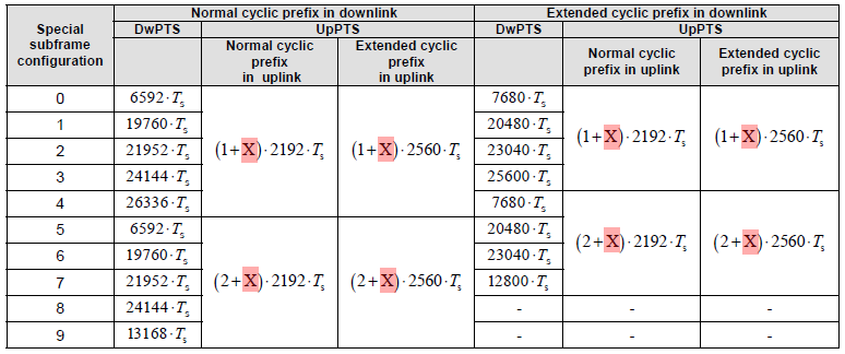
36.211 has changed since the paragraphs quoted above. In v19.3.0 the ten subframes of a type 3 radio frame are available for downlink or uplink. Clause 4.3 adds that uplink transmissions occupy one or more consecutive subframes. The Release 13 text above offers downlink only.
The table above has grown as well. It ends at special subframe configuration 9, and v19.3.0 lists configurations 0 to 10.
One line of the list at the top of this page has gained a footnote too. 36.211 now applies frame structure type 1 to FDD and to IoT NTN TDD. Clause 4.4 describes that second case in band 249.
Type 3 carries uplink now : the current clause 4.3 reads downlink or uplink, where the Release 13 text above reads downlink.A tenth special subframe configuration exists : Table 4.2-1 runs to configuration 10, and the picture above stops at 9.Type 1 is no longer FDD alone : 36.211 also applies it to IoT NTN TDD, described in clause 4.4 for band 249.The quoted paragraphs stay as they are : they carry the version they came from, so the differences are recorded beside them.
Physical Channels and Signals in Radio Frame
Now I will talk about the details of various type of physical channels that will be embedded into the frame structure shown above. The description on this page is just an overview of each physical channels. It is too much to put all the details of each physical channels in single page. I recommed you to use this as a summary (cheat sheet) for each channels and refer to other pages linked under each descriptions if you want to get further details.
PBCH
PBCH is the physical broadcast channel. A UE reads it as soon as it has found the cell. It carries the Master Information Block and nothing else, which is why the list below is short.
- It carries only the MIB.
- It is using QPSK.
- Mapped to 6 Resource Blocks (72 subcarriers), centered around DC subcarrier in sub frame 0.
- Mapped to Resource Elements which is not reserved for transmission of reference signals, PDCCH or PCHICH
- Refer to Physical Layer : PBCH and Matlab Toolbox : PBCH page for the details.
The first L Symbols
The number of symbols in that region is 1, 2 or 3. This page writes it as L, and PCFICH is what tells the UE which.
This is one of the most confusing area of the map because multiple channels are located in this area. On the first symbol is PCFICH but PCFICH takes only part of the resource blocks on the first symbol not all. PHICH is carried by this area as well. And the remaining space not occupied by PCFICH and PHICH is allocated for PDCCH.
PCFICH
PCFICH is the physical control format indicator channel. It answers one question: how many symbols the control region takes. A UE has to know that before it can decode anything else in the subframe.
- It carries the number of symbols that can be used for control channels (PDCCH and PHICH).
- Mapped to the first OFDM symbol in each of the downlink sub-frame. This contains the information on number of OFDM symbols carrying the control channels (PDCCH and PHICH). UE decode this channel to figure out how many OFDM symbols are assigned for the control channels(PDCCH and PHICH)
- It is 16 data subcarriers of the first OFDM symbol of the subframe.
- PCFICH data is carried by 4 REGs and these four REGs are evenly distributed across the whole band regardless of the bandwidth.
- The exact position of PCFICH is determined by cell ID and bandwidth.
- For further details, refer to Physical Layer : PCFICH and Matlab Toolbox : PCFICH page.
PDCCH
PDCCH is the physical downlink control channel, and it carries the scheduling decisions. Every downlink assignment and every uplink grant reaches the UE through it. A UE therefore searches it in every subframe it monitors.
- Mapped to the first L OFDM symbols in each of the downlink sub-frame.
- Number of the symbols (L) for PDCCH can be 1,2, or 3.
- Number of the symbols for PDCCH is specified by PCFICH
- PDCCH carries DCIs and the DCI carries Transport format, resource allocation, H-ARQ information related to DL-SCH, UL-SCH and PCH and other additional information depending on DCI format.
- PDCCH also carries DCI 0 which is for UL Scheduling assignment (e.g, UL Grants).
- Multiple PDCCH can be assigned in single subframe and a UE do blind decoding of all the PDCCHs.
- Modulation Scheme is QPSK.
- PDCCH is like HS-SCCH for HSDPA and PDCCH for R99, E-AGCH/E-RGCH for HSUPA
- Even though PDCCH has a lot of functions, not all of them are used at the same time so PDCCH configuration should be done flexibly.
- If you are interested in the detailed information mapping in this channel, refer to 6.8.1 of 36.211. Following is the initial descrition on this section.
- Refer to Physical Layer : PDCCH and Matlab Toolbox : PDCCH for the details
The physical downlink control channel carries scheduling assignments and other control information. A physical controlchannel is transmitted on an aggregation of one or several consecutive control channel elements (CCEs), where a control channel element corresponds to 9 resource element groups. The number of resource-element groups notassigned to PCFICH or PHICH is REG N . The CCEs available in the system are numbered from 0 and N_CCE-1 , where N_CCE = floor(N_REG/9) . The PDCCH supports multiple formats as listed in Table 6.8.1-1. A PDCCH consisting of nconsecutive CCEs may only start on a CCE fulfilling imod n = 0 , where i is the CCE number.
PHICH
PHICH carries the acknowledgement for an uplink transport block, and little else. The channel is tiny, and its timing matters more than its capacity. A UE cannot retransmit until the acknowledgement arrives.
- Carries H-ARQ Feedback for the received PUSCH
- After UE trasmitted the data in UL, it is waiting for PHICH for the ACK.
- It is like E-HICH in HSPA
- Sometimes several PHICH constitutes a PHICH group using the same resource elements.
- Refer to Physical Layer : PHICH and Matlab Toolbox : PHICH for the details
PDSCH
PDSCH is the physical downlink shared channel, and it carries the payload. The network sends all user data here, and the random access response as well. The channel takes whatever the control region leaves.
- Carries user specific data (DL Payload).
- Carries Random Access Response Message.
- It is using AMC with QPSK, 16 QAM, 64 QAM, 256 QAM modulation scheme (This modulation scheme is determined by MCS that is carried by DCI)
- Refer to Physical Layer : PDSCH and Matlab Toolbox : PDSCH for the details.
PRACH
PRACH is an uplink channel. It appears in this downlink list because the exchange it starts is answered on PDSCH. A UE uses it to reach a cell that does not yet know the UE exists.
- It carries the random access preamble
- It is occupying 72 subcarriers (6 RB) of bandwidth in the frequency domain.
- Within this channel is Random Access Preamble. This Random Access Preamble is generated with Zadoff-Chu sequence.
- Refer to RACH page and Matlab Toolbox : PRACH page for the details.
PSS
P-SS is the primary synchronization signal. It is the first thing a UE looks for in an unknown cell. Finding it fixes the slot timing and supplies part of the physical cell ID.
- Mapped to 72 active sub carriers(6 resource blocks), centered around the DC subcarrier in slot 0 (Subframe 0) and slot 10 (Subframe 5).
- Made up of 62 Zadoff Chu Sequence Values
- Used for Downlink Frame Synchronization
- One of the critical factors determining Physical Cell ID
- Refer to Physical Layer : PSS and Matlab Toolbox : PSS for the details.
May Not be a big issues for most of the case since it would be working fine for most of the device that you have for test. Otherwise it would have not been given to you for test.
However, if you are a developer working at early stage of LTE chipset, this would be one of the first signal you have to implement.
How can you find the exact location of the PSS from the sequence of IQ data captured at baseband ? This is one of the most import part of Timing Synchronization. This is one of the very tricky part of understanding LTE protocol and it would take a long time for study.
SSS
S-SS is the second signal a UE acquires, and it finishes what P-SS started. It resolves the radio frame boundary and the rest of the physical cell ID.
SSS is a specific physical layer signal that is used for radio frame synchronization. It has characterstics as listed below.
- Mapped to 72 active sub carriers(6 resource blocks), centered around the DC subcarrier in slot 0 (Subframe 0) and slot 10 (Subframe 5) in FDD.
- The sequence of SSS in subframe 0 and the one in subframe 5 are different from each other
- Made up of 62 Scrambling Sequence (based on m-sequence)
- The value in odd indexed resource element and the one in even indexed resource elements is generated by different equation
- Used for Downlink Frame Synchronization
- One of the critical factors determining Physical Cell ID
- Refer to Physical Layer : SSS and Matlab Toolbox : SSS for the details
May Not be a big issues for most of the case since it would be working fine for most of the device that you have for test. Otherwise it would have not been given to you for test.
However, If you are a developer working at early stage of LTE chipset (especially at baseband area), this would be one of the first signal you have to implement.
RS - Cell Specific
Most of the channels (e.g, PDSCH, PDCCH, PBCH etc) is for carrying a special information (a sequence of bits) and they have some higher layer channel connected to them, but Reference Signal is a special signal that exists only at PHY layer. This is not for delivering any specific information. The purpose of this Reference Signal is to deliver the reference point for the downlink power.
When UE try to figure out DL power (i.e, the power of the signal from a eNode B), it measure the power of this reference signal and take it as downlink cell power.
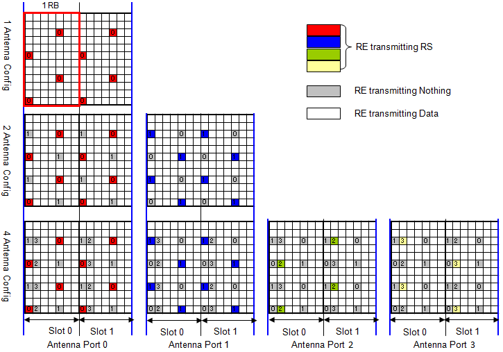
These reference signal are carried by multiples of specific Resource Elements in each slots and the location of the resource elements are specifically determined by antenna configuration.
In the figures below, Red/Blue/Green/Yellow is the part where the reference signal are carried and the resource elements marked in gray are the ones reserved for reference signal, but are not carrying Reference Signal for that specific antenna. (Follwing illustration is based on 36.211 Figure 6.10.1.2-1. Mapping of downlink reference signals (normal cyclic prefix))
< LTE Cell Specific Reference Signal (CRS) >
Following is an example of physical channel configuration and RE (Resource Element) mapping for 4 Antenna case. The measurement result is from LTE signal Analyzer measuring the LTE signal coming out of the LTE network simulator. It shows only one RB (RB0) of 20 Mhz System Bandwidth (i.e, 100 RBs in total) and was captured at Antenna port 0, 1, 2, 3 respectively while LTE network is transmitting MIB/SIBs and UE is not connected. You would notice that location of Reference Signal is different for each antenna. Due to this reference signal location difference, the REG grouping may vary slightly resuting in a little bit different location of PCFICH.
< LTE Cell Specific Reference Signal for Each Antenna >
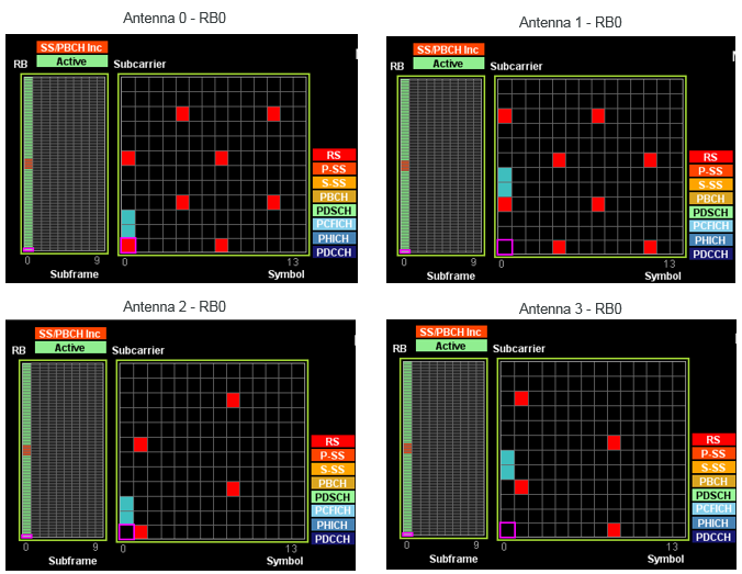
There are two different types of reference signal : Cell Specific Reference Signa and UE specific Reference Signal
- Cell Specific Reference Signal : This reference signal is being transmitted at every subframe and it spans all across the operating bandwidht. It is being transmitted by Antenna port 0,1,2,3.
- UE Specific Reference Signal : This reference signal is being transmitted within the resource blocks allocated only to a specific UE and is being transmitted by Antenna port 5.
Is the Resource element for the cell specific reference signal fixed ?
A UE has to know where to look before it has decoded anything at all. Two indices fix a reference signal, one in time and one in frequency. Only one of the two is the same in every cell.
No, the location changes according to Physical Cell ID as described below.
- The time domain index (l) for the reference signal = fixed. ( l = [0,4] )
- The frequency domain index k for the reference signal = changes according to physical cell ID as specified in 36.211 6.10.1.2 Mapping to resource element.
- main rule is : k = 6 m + (v + v_shift) mod 6, where v_shift = Physical Cell ID mod 6. For further details, refer to 36.211 6.10.1.2
What kind of value is carried by the downlink reference signal ?
The value is a pseudo random sequence generated by the algorithm defined in 36.211 6.10.1.1 Sequence Generation and described in Physical Layer : Cell Specific Reference Signal page.(Note : The uplink reference signal - DMRS (i.e, PUSCH DMRS and PUCCH DMRS) - is Zadoff Chu sequence)
One of the determining value of this sequence is Physical Cell ID, meaning that the physical cell ID influences the value of the reference signal as well.
Is CRS transmitted in any subframe type ?
At the initial phase of LTE develoyment, you haven't doubt on that every LTE subframe would carries CRS(Cell Sepecific Reference Signal) in it. But as we see more diverse types of subframe structure (FDD-frame structure Type1, TDD -frame structure Type 2, LAA - frame structure type 3), I see my confidence gets weaker. The question is 'Does every frame type(type 1, 2, 3) transmit CRS ?
The short anwer is 'YES'. More detailed answer is following as stated in 36.211 - 6.10.1 Cell-specific Reference Signal (CRS).
- CRS is transmitted in all downlink subframes for frame structure type 1,
- CRS is transmitted in all downlink subframes and DwPTS for frame structure type 2,
- CRS is transmitted in non-empty subframes for frame structure type 3
RS - MBSFN
MBSFN reference signals occupy antenna port 4. They appear only in the subframes a cell reserves for multicast. The figure below uses extended cyclic prefix, so each slot holds six symbols rather than seven.
Following is based on 36.211 Figure 6.10.2.2-1: Mapping of MBSFN reference signals (extended cyclic prefix, Δf = 15 kHz )
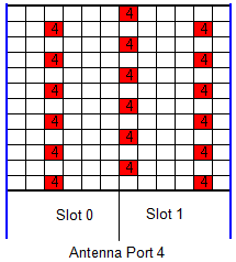
RS - UE Specific
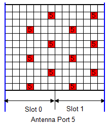
A UE specific reference signal is sent only inside the resource blocks assigned to one UE. It is sent only when the transmission mode needs it. Antenna port 5 is the Release 8 case, and ports 7 to 10 arrived with the later transmission modes.
Following is based on 36.211 Figure 6.10.3.2-1: Mapping of UE-specific reference signals, antenna port 5 (normal cyclic prefix)
< Reference Signal - UE Specific - Antenna Port 5 >
< Reference Signal - UE Specific - Antenna Port 7,8,9,10 >
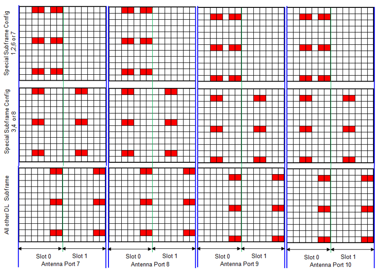
RS - Positioning
Positioning reference signals occupy antenna port 6. They let a UE measure the arrival time of several cells at once. The pattern is deliberately sparse and spread out, which is what makes a time difference measurable.
Following is based on 36.211 Figure 6.10.4.2-1: Mapping of positioning reference signals (normal cyclic prefix)
< Reference Signal - Positioning - Antenna Port 6 >
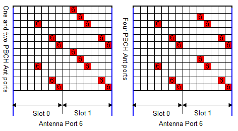
- The picture holds two panels, and both are antenna port 6. The left one is for a cell with one or two PBCH antenna ports, the right one for a cell with four.
- The occupied resource elements sit at a different subcarrier in each symbol, rather than repeating at one. A receiver therefore sees the port across many frequencies within a single subframe.
RS - CSI
CSI reference signals cover antenna ports 15 to 22. They are there for channel measurement rather than demodulation. They are far sparser than the cell specific signals, because a UE only has to estimate the channel well enough to report it.
Following is based on 36.211 Figure 6.10.5.2-1: Mapping of CSI reference signals (CSI configuration 0, normal cyclic prefix)
< Reference Signal - CSI - Antenna Port 15,16,17,18,19,20,21,22 >
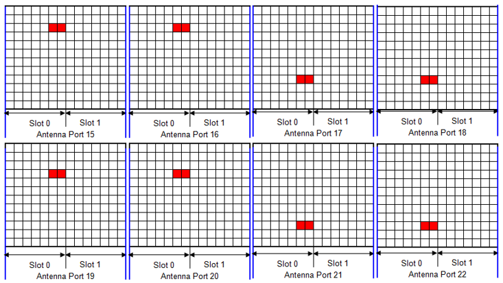
- Each of the eight panels carries a single pair of resource elements. That is how little a channel measurement needs.
- Several ports share the same pair of positions in the slot. The eight ports therefore do not need eight separate places in the grid.
Whole Frame Snapshot
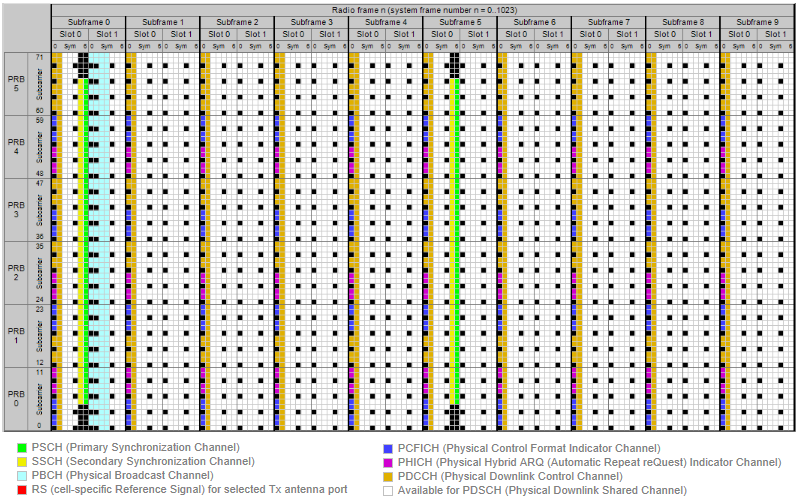
Following is a snapshot showing the whole channels described above. Of course this is not to give you the detailed information. It is to give you a overall picture of a whole frame. Would you be able to identify the locations of each channels described above ? Just try it, it will be a good practice.
Each components in this grid has it's own role and used in various different context. If you are interested in how each of these channels are used in real communication process, refer to following sections in Quick Reference page.
- Cell ID Detection and System Information Detection
- Uplink Data Transmission Scheduling - Persistent Scheduling
- Uplink Data Transmission Scheduling - Non Persistent Scheduling
- Downlink Data transmission Process
- Channel Coding Processing for DL SCH/PCH/MCH
- Physical Channel Processing
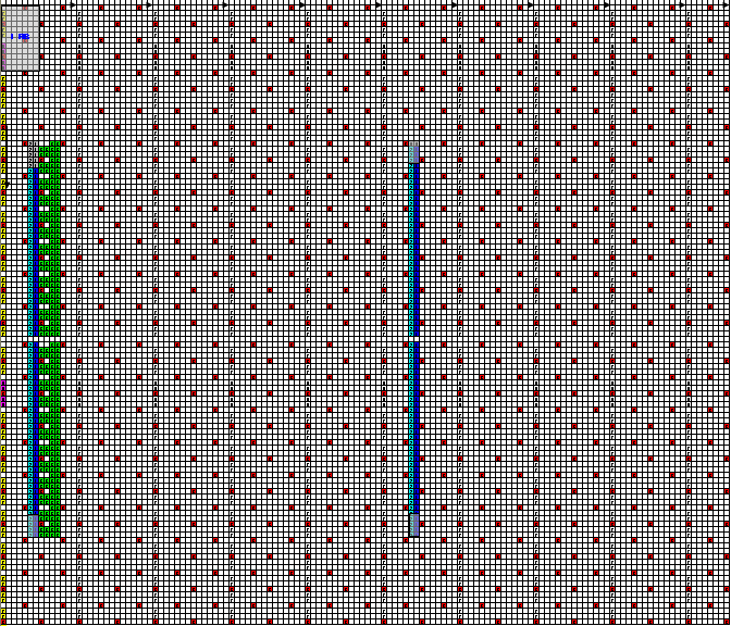
- The red dots across the whole grid are the cell specific reference signals. They appear in every resource block and in every subframe, which is what lets a UE estimate the channel anywhere in the band.
- Two narrow coloured columns interrupt that pattern. They sit in the middle of the band, in subframe 0 and subframe 5, and hold the synchronization signals and the broadcast channel.
- Everything left white is available for data, which is most of the grid.
Those two columns are why a UE can find a cell it knows nothing about. They always occupy the middle 6 resource blocks, whatever the system bandwidth. A receiver can search a fixed window of 1.08 MHz and ignore the rest.
The reference signals cost a fixed share of every subframe : they are spread over the grid rather than gathered in one place.The middle 6 resource blocks are special : synchronization and broadcast sit there at a fixed width, whatever the carrier bandwidth.Twice per frame is enough : subframe 0 and subframe 5 both carry the pair, 5 ms apart.
Physical Channels in Communication
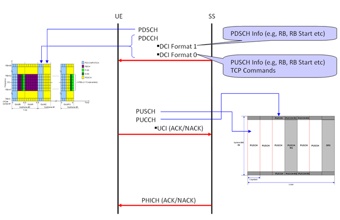
Following diagram shows overall sequence of Uplink/Downlink data transmission. You would be able to associate the data transmission sequence diagram and the specific location of each channels in DL/UL frame structure.
< Physical Channels in Communication >
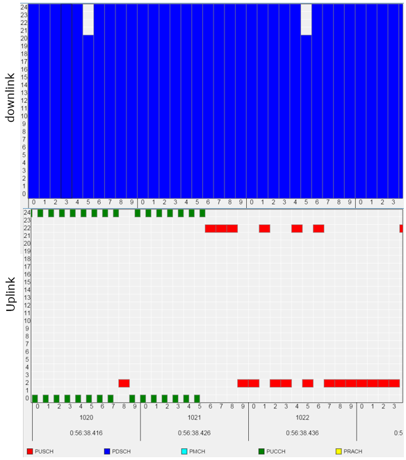
Following is an example of channel map that is happening during real communication between UE and Amarisoft LTE Network Simulator. It has an excellent log analysis tool that shows physicall channel mapping for every subframe as shown below. If you roll over mouse pointer onto each channel, it will give you the detailed physical parameter. It would be very helpful for troubleshooting and for study. This example is a snapshot while I was watching YouTube over the phone.
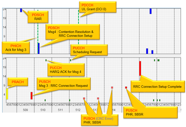
Now let's look at another example, which might look more complicated and confusing but hopefully look more interesting :). This shows an example of what's happening during the initial process (RACH process) after you turn on your mobile phone.
Again, the log and background RB map is from Amarisoft LTE Network simulator. All the labels were put manually (If you roll over the mouse pointer onto each channel it shows some detailed information, but it would not show information on the exact contents. This is understandable.. because Physical channel by itself does not have any detailed knowledge on the contents).
< LTE RB Map - Example 02 - 1 >
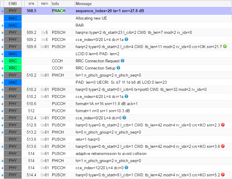
How can I figure out all the details printed on each labels shown above ? It came from the text based log as shown below.
It took me almost an hour to pul all the lables shown above based on the log below. However, this can be a good practice if you are at learning phase of LTE protocol.. or you HAVE TO go through this tedious process when you are in troubleshooting situation.
< LTE RB Map - Example 02 - 2 >

Gallery
I would not put much of the comments for the following captures. These captures are for your practice to associate what you read in previous sections to the real life signal pattern.
< Spectrogram - LTE FDD DL - Radio Frame >
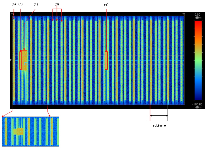
The vertical stripes above are OFDM symbols, and the span marked at the lower right is one subframe. The brighter columns repeat at a regular spacing. That is the signature of the symbols carrying the cell specific reference signals. Two thin horizontal lines run across the middle of the band. The red boxes on that line surround the region where the synchronization signals sit.
< Spectrogram - LTE FDD DL - PBCH >
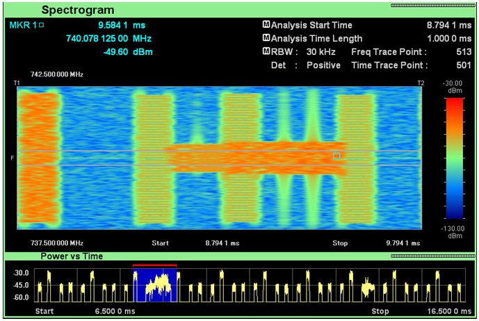
The instrument above is set to a 1 ms window, which is one subframe. It reports that window as 8.7941 ms to 9.7941 ms. The wide red band across the middle of the span is the center of the carrier holding the broadcast channel. The trace at the bottom is power against time over 10 ms, with the measured subframe highlighted.
< Spectrogram - LTE FDD DL - PSS/SSS>
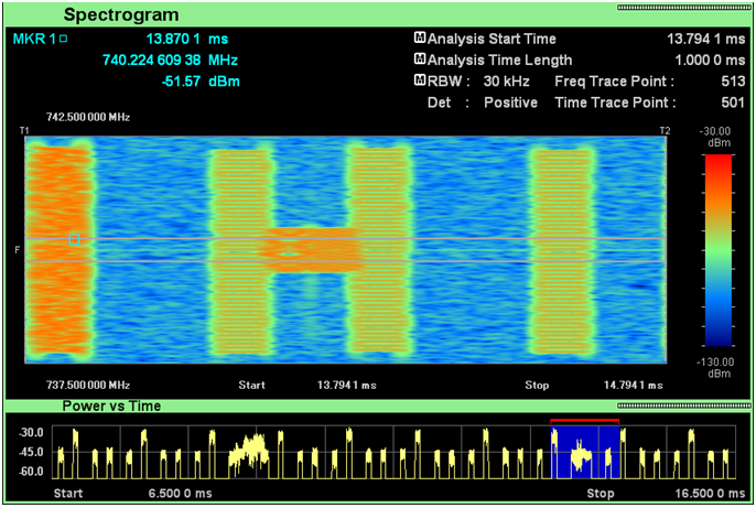
The capture above is the same measurement taken 5 ms later. The difference is in how long the center of the band stays busy. The synchronization signals occupy two symbols where the broadcast channel occupies four. The red band is therefore short here and long in the capture before it.
< Spectrogram - LTE FDD DL - Each Symbol >
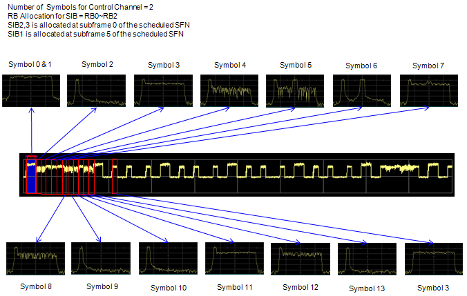
The last capture breaks one subframe into its symbols and shows the spectrum of each. The notes at the top give the conditions. The control region is two symbols, and the system information sits in resource blocks 0 to 2. SIB2 and SIB3 are in subframe 0, and SIB1 is in subframe 5.
The small plots differ in how much of the band each symbol occupies. Matching them against the channel map earlier on this page is the exercise.
Reference
[1] 36.211 : 3GPP - E-UTRA; Physical channels and modulation, v19.3.0. Clause 4 defines the three frame structures. Table 4.2-1 gives the special subframe configurations and Table 4.2-2 the uplink-downlink configurations. Clause 4.3 covers frame structure type 3, and clause 4.4 covers type 1 for IoT NTN TDD.