This page will explain about various aspect of Measurement Process that is happening in a LTE. In any technology, Measurement is done roughly at two stage. One is measurement in Idle mode and the other one is in Connected mode. Idle mode measurement is mainly for Cell Selection and Reslection process and most of idle mode measurement criteria is determined by SIB messages, the connected mode measurement is mostly for Handover or CSFB and the measurement criteria is determined by specific RRC messages dedicated for a specific UE.
This page will deal with connected mode measurement process only. Idle mode measurement is not the scope of this page.
In terms of RRC Message, you may say Measurement Process would be a simple one, that is,
i) eNB sends an RRC message indicating what kind of items to be measured and
ii) UE sends an RRC message that carries the result of the measurement
You're right at the high level, but you will find it very tricky if you are asked to create the RRC message with all the detailed parameters (IE : Information Elements) to trigger UE to perform the specific measurement. There are so many details you need to understand.
On UE protocol stack as well, implmentating the measurement process would be one of the most challenging item. According to my experience, it tend to take huge time and effort to implement all sorts of measurement algorithm and take a lot of time for verification process as well.
Topics on this page are as follows.
- LTE Measurement Report Trigger (EVENT for Measurement Report)
- Measurement GAP
- Layer 3 Filtering for Measurement Report
- Measurement with Examples
- Example 1 > - Measuring RSRP, RSRQ for current Cell
- Example 2 > - Event Based Measurement : A1, A2, A3
- Example 3 > - Event Based Measurement : A5
- Measurement with CGI report
- Frequent Issues Regarding Measurement Report
- Get the Test Procedure and Log / Amarisoft TechAcademy
LTE Measurement Report Trigger (EVENT for Measurement Report)
One of the most important step for Handover is Measurement Report from UE before the handover. Network make a decision on whether it will let UE handover or not, based on the measurement value from UE. There are many different measurement items and many different ways to measure the signal quality of the current cell (serving cell) and target cell.
Ideally a network let UE to report the signal quality (usually RSRP) of the current cell (serving cell) and target cell and set the arbitrary rule for handover. But this can be too complicated and too much load on network since the network may need a multiple times of consecutive measurement result in stead of using only a single or a couple of measured signal quality value (Can you think of why only one or a couple of signal quality measurement (RSRP) would not be a good enough for this kind of decision making ?).
As a kind of solution, 3GPP defines several set of predefined set of measurement report mechanism to be performed by UE. These predefined measurement report type is called "Event". What kind of "event" a UE has to report is specified by RRC Connection Reconfiguration message as follows (shown in red).
+-rrcConnectionReconfiguration ::= SEQUENCE
+-rrc-TransactionIdentifier ::= INTEGER (0..3) [0]
+-criticalExtensions ::= CHOICE [c1]
+-c1 ::= CHOICE [rrcConnectionReconfiguration-r8]
+-rrcConnectionReconfiguration-r8 ::= SEQUENCE [100000]
+-measConfig ::= SEQUENCE [01010111111] OPTIONAL:Exist
| +-measObjectToRemoveList ::= SEQUENCE OF OPTIONAL:Omit
| +-measObjectToAddModList ::= SEQUENCE OF SIZE(1..maxObjectId[32]) [1]
| | +-MeasObjectToAddMod ::= SEQUENCE
| | +-measObjectId ::= INTEGER (1..maxObjectId[32]) [1]
| | +-measObject ::= CHOICE [measObjectEUTRA]
| | +-measObjectEUTRA ::= SEQUENCE [100000]
| | +-carrierFreq ::= INTEGER (0..maxEARFCN[65535]) [6300]
| | +-allowedMeasBandwidth ::= ENUMERATED [mbw25]
| | +-presenceAntennaPort1 ::= BOOLEAN [FALSE]
| | +-neighCellConfig ::= BIT STRING SIZE(2) [01]
| | +-offsetFreq ::= ENUMERATED [dB0] OPTIONAL:Exist
| | +-cellsToRemoveList ::= SEQUENCE OF OPTIONAL:Omit
| | +-cellsToAddModList ::= SEQUENCE OF OPTIONAL:Omit
| | +-blackCellsToRemoveList ::= SEQUENCE OF OPTIONAL:Omit
| | +-blackCellsToAddModList ::= SEQUENCE OF OPTIONAL:Omit
| | +-cellForWhichToReportCGI ::= INTEGER OPTIONAL:Omit
| +-reportConfigToRemoveList ::= SEQUENCE OF OPTIONAL:Omit
| +-reportConfigToAddModList ::= SEQUENCE OF SIZE(1..maxReportConfigId[32]) [1]
| | +-ReportConfigToAddMod ::= SEQUENCE
| | +-reportConfigId ::= INTEGER (1..maxReportConfigId[32]) [1]
| | +-reportConfig ::= CHOICE [reportConfigEUTRA]
| | +-reportConfigEUTRA ::= SEQUENCE
| | +-triggerType ::= CHOICE [event]
| | | +-event ::= SEQUENCE
| | | +-eventId ::= CHOICE [eventA3]
| | | | +-eventA3 ::= SEQUENCE
| | | | +-a3-Offset ::= INTEGER (-30..30) [0]
| | | | +-reportOnLeave ::= BOOLEAN [FALSE]
| | | +-hysteresis ::= INTEGER (0..30) [0]
| | | +-timeToTrigger ::= ENUMERATED [ms640]
| | +-triggerQuantity ::= ENUMERATED [rsrp]
| | +-reportQuantity ::= ENUMERATED [both]
| | +-maxReportCells ::= INTEGER (1..maxCellReport[8]) [1]
| | +-reportInterval ::= ENUMERATED [ms1024]
| | +-reportAmount ::= ENUMERATED [r1]
Brief description you can find from 3GPP 36.331 5.5.4 Measurement report triggering is as follows. You will see pretty complicated description of the exact procedure of each of these events, but if you convert those descriptions into a graphical format it would be much easier/intuitive to understand the nature of these events.
|
Event Type |
Description |
|
Event A1 |
Serving becomes better than threshold |
|
Event A2 |
Serving becomes worse than threshold |
|
Event A3 |
Neighbour becomes offset better than serving |
|
Event A4 |
Neighbour becomes better than threshold |
|
Event A5 |
Serving becomes worse than threshold1 and neighbour becomes better than threshold2 |
|
Event A6 |
Neighbour become offset better than S Cell (This event is introduced in Release 10 for CA) |
|
Event B1 |
Inter RAT neighbour becomes better than threshold |
|
Event B1-NR |
NR neighbour becomes better than threshold |
|
Event B2 |
Serving becomes worse than threshold1 and inter RAT neighbour becomes better than threshold2 |
|
Event B2-NR |
Serving becomes worse than threshold1 and NR neighbour becomes better than threshold2 |
|
Event C1 |
CSI-RS resource becomes better than threshold |
|
Event C2 |
CSI-RS resource becomes offset better than reference CSI-RS resource |
|
Event W1 |
WLAN becomes better than a threshold |
|
Event W2 |
All WLAN inside WLAN mobility set becomes worse than threshold1 and a WLAN outside WLAN mobility set becomes better than threshold2 |
|
Event W3 |
All WLAN inside WLAN mobility set becomes worse than a threshold |
|
Event V1 |
The channel busy ratio is above a threshold |
|
Event V2 |
The channel busy ratio is below a threshold |
|
Event H1 |
The Aerial UE height is above a threshold |
|
Event H2 |
The Aerial UE height is below a threshold |
Following is an illustration showing possible conditions triggering each of the events A1~A6. Just suppose that you become a UE and generating measurement report following along the timeline. If you don't get confused, you are high quality UE :)

Simply put, Measurement Report is triggered by whether the measured value crosses (goes higher or goes lower) a certain target value. The target value can be set by one of two methods. One is to use threshold which is a kind of absolute value and the other one is to use Offsef value which is a kind relative value with a reference to 'something' like serving cell value. However, in reality the measured value can fluctuate pretty frequently sometimes by measurement error by UE modem and sometimes by the fluctuation of Radio channel itself. In most case, the network would not be interested in such a small fluctuation and does not want to get too many measurement reports triggered by such a small fluctuation. To provent this kind of unnecessarily frequent measurement report caused by small range of fluctuation, the parameter called 'Hysterisis' is introduced. The role of Hysterysis can be illustrated as below and hope this would make sense to you.

Measurement GAP
Before the handover, UE normally measure the cell power (signal quality) of the target cell and report it to the network, so that network can make a decision whether to allow UE to handover to the target cell or not.
It is not a big issue to measure the signal quality of the target cell if the target cell is at the same frequency as the current cell (Intrafrequency measurement). But there would be an issue when the target cell is at a different frequency from the current cell (Interfrequency measurement). Just in terms of logical sense of view, the simplest solution for Interfrequency measurement, the simplest solution for this would be to implement two RF tranciever on UE. However, there are some practical problems with this kind of two tranciever solution. One of the problems is cost issue. It would require additional cost to implement the additional tranciever. The other problem would be the possible interference between the current frequency and target frequency especially when the current frequency and target frequency are close to each other.
So they come out with a special techique called "Measurement GAP". This is the same concept as "Compressed Mode" in UMTS. The idea of the Measurement GAP is to create a small gap during which no transmission and reception happens. since there is no signal transmission and reception during the gap, UE can switch to the target cell and perform the signal quality measurement and come back to the current cell.
To make this work seamlessly, there should be a well established agreement between UE and Network about the gap definition (e.g, Starting Position of the Gap, Gap length, number of Gaps etc) and this agreement is established by MeasGapConfig IE of RRC Connection Reconfiguration message.
Measurement GAP for LTE and Legacy (UTRAN, GRAN etc)
If you see this part, RRC contents is small but you need to go through several steps as followsto fully understand the implementation of the measurement GAP. (The spreadsheet shown at the bottom is here. Let me know if you find any problem with this spreadsheet).

One of the complications about the measurement GAP would be how to schedule data transmission around the gap. Situation would be more complicated than you may think because we have to think about not only the data transmission itself, but also the scheduling grant and ACK/NACK transmission. One of possible scheduling example around measurement gap is as follows.

Measurement GAP for LTE and NR
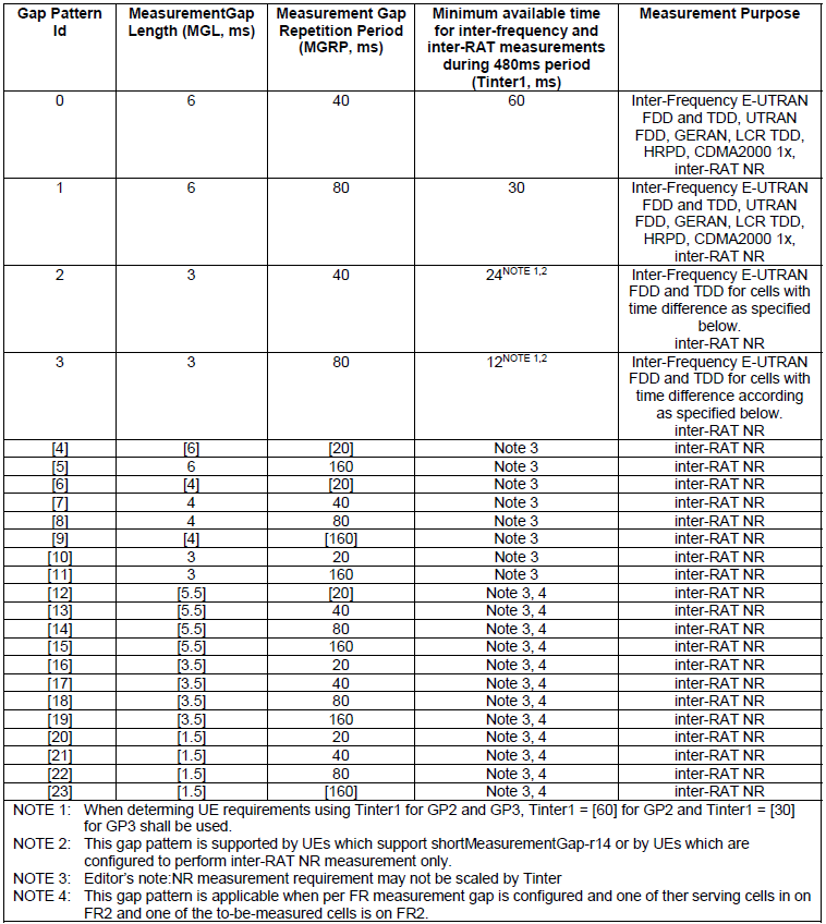
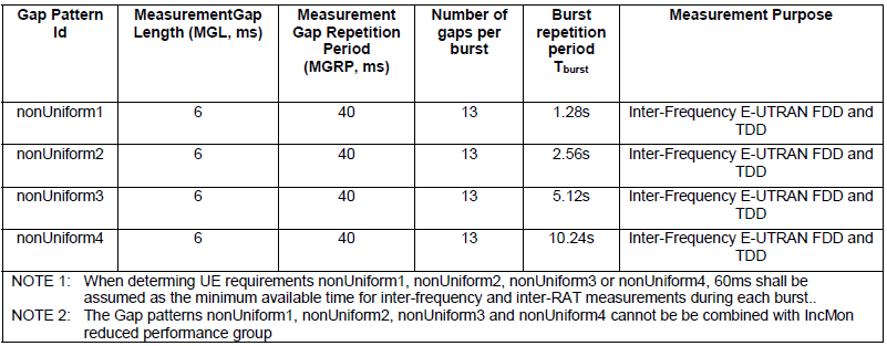
As LTE evolves, we got increasing number of measurement gap definition and with the introduction of NR, this list got exploded as below.
Fundamental logic of the GAP setting is same as in LTE and Legacy case as explained above. Recap the procedure, it can be summarized as follows.
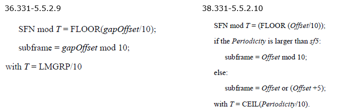
i) Get the Gap Pattern ID from RRC MeasGapConfig and additional SMTC parameter from
ii) Get the detailed Gap Setting Parameters for the Gap Pattern from 36.133 Table 8.1.2.1-1
iii) Determine Gap Subframe based on the condition described as below
Rules may sound simple ? It may sound simple, but you would not know how complicated it is before you really try it. Rehan has put a lot of his time and effort on this and completed the excel spreadsheet to show the gap settings for each subframe automatically according to the parameters you set. He kindly allowed me to share the spreadsheet for readers. Click here to get the file.
Followings a few examples from the spreadsheet.
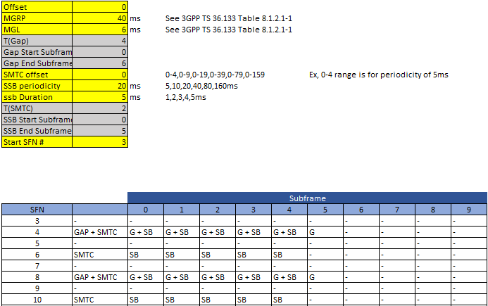
Basically overall RRC Structure is similar to LTE/Legacy case explained above, but there are a couple of additiona flags a shown and a lot of different gapoffset as shown below.
From 36.331
MeasConfig ::= SEQUENCE {
....
measGapConfig MeasGapConfig OPTIONAL,
...
[[
measGapConfigPerCC-List-r14 MeasGapConfigPerCC-List-r14 OPTIONAL,
measGapSharingConfig-r14 MeasGapSharingConfig-r14 OPTIONAL
]],
[[
fr1-Gap-r15 BOOLEAN OPTIONAL, -- Need ON
mgta-r15 BOOLEAN OPTIONAL -- Need ON
]],
[[
measGapConfigDensePRS-r15 MeasGapConfigDensePRS-r15 OPTIONAL,
heightThreshRef-r15 CHOICE {
release NULL,
setup INTEGER (0..31)
} OPTIONAL --Need ON
]]
}
MeasGapConfig ::= CHOICE {
release NULL,
setup SEQUENCE {
gapOffset CHOICE {
gp0 INTEGER (0..39),
gp1 INTEGER (0..79),
...,
gp2-r14 INTEGER (0..39),
gp3-r14 INTEGER (0..79),
gp-ncsg0-r14 INTEGER (0..39),
gp-ncsg1-r14 INTEGER (0..79),
gp-ncsg2-r14 INTEGER (0..39),
gp-ncsg3-r14 INTEGER (0..79),
gp-nonUniform1-r14 INTEGER (0..1279),
gp-nonUniform2-r14 INTEGER (0..2559),
gp-nonUniform3-r14 INTEGER (0..5119),
gp-nonUniform4-r14 INTEGER (0..10239),
gp4-r15 INTEGER (0..19),
gp5-r15 INTEGER (0..159),
gp6-r15 INTEGER (0..19),
gp7-r15 INTEGER (0..39),
gp8-r15 INTEGER (0..79),
gp9-r15 INTEGER (0..159),
gp10-r15 INTEGER (0..19),
gp11-r15 INTEGER (0..159)
}
}
}
From 38.331
MeasObjectNR ::= SEQUENCE {
}
SSB-MTC ::= SEQUENCE {
periodicityAndOffset CHOICE {
sf5 INTEGER (0..4),
sf10 INTEGER (0..9),
sf20 INTEGER (0..19),
sf40 INTEGER (0..39),
sf80 INTEGER (0..79),
sf160 INTEGER (0..159)
},
duration ENUMERATED { sf1, sf2, sf3, sf4, sf5 }
}
SSB-MTC2 ::= SEQUENCE {
pci-List SEQUENCE (SIZE (1..maxNrofPCIsPerSMTC)) OF PhysCellId OPTIONAL,
periodicity ENUMERATED {sf5, sf10, sf20, sf40, sf80, spare3, spare2, spare1}
}
< 36.133 v15.3 - Table 8.1.2.1-1: Gap Pattern Configurations supported by the UE >
< 36.133 v15.3 - Table 8.1.2.1-2: Gap Pattern Configurations for UE supporting low density burst gap pattens >
Layer 3 Filtering for Measurement Report
To be honest, I've never paid attention to this parameter before, but lately I heard an apisode of a serious field problem (too frequent handover failure) which was caused by a wrong implementation of this filter. It is the motivation for me to look into this parameter.
It is about the parameter for Layer 3 filtering for the measurement report value which is specified in rrcConnectionReconfiguration as specified below (in blue)
+-rrcConnectionReconfiguration-r8 ::= SEQUENCE [100000]
+-measConfig ::= SEQUENCE [01010111111] OPTIONAL:Exist
| +-measObjectToRemoveList ::= SEQUENCE OF OPTIONAL:Omit
| +-measObjectToAddModList ::= SEQUENCE OF SIZE(1..maxObjectId[32]) [1]
| | +-MeasObjectToAddMod ::= SEQUENCE
| | +-measObjectId ::= INTEGER (1..maxObjectId[32]) [1]
| | +-measObject ::= CHOICE [measObjectEUTRA]
| +-reportConfigToRemoveList ::= SEQUENCE OF OPTIONAL:Omit
| +-reportConfigToAddModList ::= SEQUENCE OF SIZE(1..maxReportConfigId[32]) [1]
| | +-ReportConfigToAddMod ::= SEQUENCE
| | +-reportConfigId ::= INTEGER (1..maxReportConfigId[32]) [1]
| | +-reportConfig ::= CHOICE [reportConfigEUTRA]
| | +-reportConfigEUTRA ::= SEQUENCE
| | +-triggerType ::= CHOICE [event]
| | | +-event ::= SEQUENCE
| | | +-eventId ::= CHOICE [eventA3]
| | | | +-eventA3 ::= SEQUENCE
| | | | +-a3-Offset ::= INTEGER (-30..30) [0]
| | | | +-reportOnLeave ::= BOOLEAN [FALSE]
| | | +-hysteresis ::= INTEGER (0..30) [0]
| | | +-timeToTrigger ::= ENUMERATED [ms640]
| | +-triggerQuantity ::= ENUMERATED [rsrp]
| | +-reportQuantity ::= ENUMERATED [both]
| | +-maxReportCells ::= INTEGER (1..maxCellReport[8]) [1]
| | +-reportInterval ::= ENUMERATED [ms1024]
| | +-reportAmount ::= ENUMERATED [r1]
| +-measIdToRemoveList ::= SEQUENCE OF OPTIONAL:Omit
| +-measIdToAddModList ::= SEQUENCE OF SIZE(1..maxMeasId[32]) [1] OPTIONAL:Exist
| | +-MeasIdToAddMod ::= SEQUENCE
| | +-measId ::= INTEGER (1..maxMeasId[32]) [1]
| | +-measObjectId ::= INTEGER (1..maxObjectId[32]) [1]
| | +-reportConfigId ::= INTEGER (1..maxReportConfigId[32]) [1]
| +-quantityConfig ::= SEQUENCE [1111] OPTIONAL:Exist
| | +-quantityConfigEUTRA ::= SEQUENCE [11] OPTIONAL:Exist
| | | +-filterCoefficientRSRP ::= ENUMERATED [fc0] OPTIONAL:Exist
| | | +-filterCoefficientRSRQ ::= ENUMERATED [fc0] OPTIONAL:Exist
fc0 in filterCoefficientRSRP IE means "Do not apply Layer 3 filter and report the raw measured data". If filterCoefficientRSRP use a value other than fc0, it means "Apply Layer 3 filter with the specified the coefficient". The filter function and the meaning of each parameter is defined in 3GPP 36.331 5.5.3.2 Layer 3 filtering as follows.
Fn = (1 - a) · Fn-1 + a · Mn
- Fn: Updated filtered measurement result.
- Fn-1: Previous filtered measurement result.
- Mn: Latest raw measurement from the physical layer.
- a: Filter coefficient, defined as a = 1/2(k/4), where k is the filterCoefficient (e.g., filterCoefficientRSRP).
Where:
The filtered result Fn is used for evaluating reporting criteria or measurement reporting.
The coefficient a determines the weight of the new measurement (Mn) versus the previous filtered result (Fn-1):
- If k = 0, then a = 1/2(0/4) = 1. This means Fn = Mn, so no filtering occurs.
- If k is larger, a becomes smaller, giving more weight to Fn-1, resulting in heavier smoothing.
a = 1/2(k/4)
The parameter filterCoefficientRSRP set to fc0 (k = 0) disables filtering, reporting raw data directly, which caused the field issue.
The Issue with filterCoefficientRSRP = fc0
The configuration shows:
- quantityConfigEUTRA → filterCoefficientRSRP = ENUMERATED {fc0} [OPTIONAL:exist]
With k = 0:
a = 1/2(0/4) = 1
Fn = (1 - 1) · Fn-1 + 1 · Mn = Mn
This results in unfiltered measurements, leading to:
- Unnecessary handovers due to rapid RSRP fluctuations.
- Ping-pong effects between cells.
- Poor network performance from noisy data.
A non-zero filterCoefficientRSRP (e.g., fc4) should be used for smoothing.
The Layer 3 Filtering Algorithm with an Example
- Raw RSRP measurements: [-90, -92, -88, -94, -89] dBm.
- Initial F0 = M1 = -90 dBm.
- Compare fc0 (k = 0) and fc4 (k = 4).
a = 1/2(0/4) = 1
Fn = Mn
|
Time (n) |
Raw Measurement (Mn) |
Filtered Result (Fn) |
|---|---|---|
|
1 |
-90 dBm |
-90 dBm (initial) |
|
2 |
-92 dBm |
-92 dBm |
|
3 |
-88 dBm |
-88 dBm |
|
4 |
-94 dBm |
-94 dBm |
|
5 |
-89 dBm |
-89 dBm |
Observation: No smoothing; sudden drops (e.g., -88 to -94) may trigger unnecessary handovers.
a = 1/2(4/4) = 1/21 = 0.5
Fn = 0.5 · Fn-1 + 0.5 · Mn
|
Time (n) |
Raw Measurement (Mn) |
Filtered Result (Fn) |
|---|---|---|
|
1 |
-90 dBm |
-90 dBm (initial) |
|
2 |
-92 dBm |
0.5 · (-90) + 0.5 · (-92) = -91 dBm |
|
3 |
-88 dBm |
0.5 · (-91) + 0.5 · (-88) = -89.5 dBm |
|
4 |
-94 dBm |
0.5 · (-89.5) + 0.5 · (-94) = -91.75 dBm |
|
5 |
-89 dBm |
0.5 · (-91.75) + 0.5 · (-89) = -90.375 dBm |
Observation: Smoothing reduces the impact of sudden drops (e.g., -89.5 to -91.75), stabilizing decisions.
Why filtering the measurement ?
Filtering the measurement is a critical process in wireless communication systems, particularly in 3GPP networks like LTE and NR, where devices continuously monitor signal strength and quality (e.g., RSRP) to ensure seamless mobility and reliable connectivity. Raw measurements from the physical layer are inherently noisy due to environmental factors such as fading, interference, and device movement, which can lead to erratic behavior if used directly for decision-making. By applying Layer 3 filtering, the system smooths these fluctuations, providing a more stable and accurate representation of the signal, which helps prevent unnecessary handovers, reduces network strain, and enhances overall performance, ensuring a consistent user experience even in challenging conditions.
Without filtering, these measurements can be very noisy due to things like signal fading or interference, leading to several problems:
- Unnecessary Handovers: Raw measurements can fluctuate a lot, even if the change is temporary. For example, a brief drop in signal strength might make the device (UE) think it needs to switch to another cell, triggering a handover. This can happen too often, overloading the network and potentially disrupting the user’s connection.
- Ping-Pong Effects: If the signal measurements are unstable, the device might keep switching back and forth between two cells. For instance, if the signal strength jumps up and down rapidly, the device could hand over to a new cell, then immediately switch back to the original one, creating a "ping-pong" loop. This wastes resources and can cause call drops or data interruptions.
- Poor Network Performance: Unfiltered, noisy measurements can confuse the network. The network might not hand over to a better cell when it should, or it might delay a necessary handover. This can lead to lower data speeds, dropped calls, or a generally unreliable connection.
- Instability in Reporting: When the device sends these erratic measurements to the network, the network struggles to make consistent decisions about managing the connection. This instability can make the whole system less reliable.
Adjust filterCoefficientRSRP to a non-zero value:
- fc4 (k = 4, a = 0.5) for moderate smoothing.
- fc6 (k = 6, a ≈ 0.353) for heavier smoothing.
Choose k based on scenario:
- High mobility: Lower k (e.g., fc2 or fc4).
- Static/low mobility: Higher k (e.g., fc6 or fc8).
Measurement with Examples
In 3GPP networks (LTE and NR), the eNodeB (eNB) in LTE or gNodeB (gNB) in NR directs the User Equipment (UE) to perform measurements through the Radio Resource Control (RRC) protocol. This process ensures the network can manage mobility (e.g., handovers) and optimize radio resource usage based on the UE's measurements of signal strength and quality. From an RRC perspective, this involves configuring the UE with measurement instructions, defining what to measure, how to filter and process the measurements, and when to report them back to the network. Below, I’ll explain this step-by-step in a human-readable format, focusing on LTE (eNB), but the concepts are similar in NR with some differences in terminology.
From an RRC perspective, the eNB’s ability to direct the UE to perform measurements ensures the network can maintain optimal connectivity. By configuring what, how, and when to measure and report, the eNB can make informed decisions about handovers, load balancing, and interference management, all while minimizing signaling overhead and ensuring a stable user experience.
RRC Connection Setup and Measurement Configuration
The process begins when the UE establishes an RRC connection with the eNB, typically during the transition from RRC_IDLE to RRC_CONNECTED state (e.g., when the UE initiates a call or data session). Once connected, the eNB sends measurement instructions to the UE using an RRC Connection Reconfiguration message, which is a key RRC message used to configure various UE behaviors, including measurements.
Inside this message, the eNB includes a Measurement Configuration (often abbreviated as MeasConfig) information element (IE). This MeasConfig tells the UE what measurements to perform, how to process them, and when to report the results. The main components of MeasConfig relevant to measurements are:
Measurement Objects (MeasObject) : These specify what the UE should measure. For example, the eNB might instruct the UE to measure the serving cell’s frequency (e.g., E-UTRA frequency) and neighboring cells’ frequencies. In LTE, this could include intra-frequency (same frequency as the serving cell), inter-frequency (different E-UTRA frequencies), or inter-RAT (e.g., frequencies for UMTS or GSM). An example is measObjectEUTRA, which defines the E-UTRA frequency to measure, along with parameters like the frequency band and cell-specific offsets.Report Configuration (ReportConfig) : This defines the criteria for reporting the measurements back to the eNB. For instance, it specifies events that trigger a measurement report, such as:- Event A1: Serving cell becomes better than a threshold (e.g., good signal strength, so stop looking for other cells).
- Event A3: A neighboring cell becomes better than the serving cell by an offset (e.g., triggering a handover).
- Event A4: A neighboring cell becomes better than a threshold. The ReportConfig also includes parameters like the time-to-trigger (how long the condition must hold before reporting) and the report interval (how often to send periodic reports if configured).
Quantity Configuration (QuantityConfig) : This defines how the UE should process the measurements, including the filtering parameters. For example, quantityConfigEUTRA specifies the filterCoefficientRSRP and filterCoefficientRSRQ to smooth the RSRP (Reference Signal Received Power) and RSRQ (Reference Signal Received Quality) measurements, as we discussed earlier with Layer 3 filtering.Measurement Identity (MeasId) : This links a Measurement Object with a Report Configuration. For example, MeasId #1 might link measObjectEUTRA (measure frequency X) with reportConfigEUTRA (report when Event A3 occurs). The UE uses this to know which measurements to perform and when to report them.Other Parameters : The MeasConfig may also include parameters like the measurement gap configuration (to allow the UE to measure inter-frequency or inter-RAT cells without interfering with data transmission) and the s-Measure (a threshold for the serving cell’s RSRP below which the UE starts measuring neighboring cells).
UE Performs the Measurements
Once the UE receives the MeasConfig via the RRC Connection Reconfiguration message, it starts performing the measurements as instructed. The UE measures the specified quantities (e.g., RSRP, RSRQ) on the defined frequencies or cells:
- The UE uses its physical layer to take raw measurements of the serving cell and neighboring cells.
- These raw measurements are passed to the UE’s Layer 3 (RRC layer), where they are filtered using the Layer 3 filtering mechanism we discussed earlier:
- Fn = (1 - a) · Fn-1 + a · Mn, where a = 1/2(k/4), and k is the filterCoefficient (e.g., filterCoefficientRSRP).
- The filtered measurements are then evaluated against the reporting criteria defined in the ReportConfig.
UE Evaluates Reporting Criteria
The UE checks if the filtered measurements meet the conditions specified in the ReportConfig. For example:
- For Event A3 (neighbor becomes better than serving by an offset), the UE compares the filtered RSRP of the serving cell and a neighboring cell. If the neighbor’s RSRP exceeds the serving cell’s RSRP by a defined offset (e.g., 3 dB) for a specified time-to-trigger (e.g., 320 ms), the event is triggered.
- For periodic reporting, the UE might be configured to send measurement reports at regular intervals (e.g., every 480 ms), regardless of events.
UE Sends Measurement Reports to the eNB
When a reporting condition is met (e.g., Event A3 is triggered), the UE sends a Measurement Report message to the eNB via the RRC protocol. This message includes:
- The MeasId that triggered the report.
- The filtered measurement results for the serving cell and any neighboring cells that meet the criteria (e.g., RSRP and RSRQ values).
- Cell identities (e.g., Physical Cell ID) for the measured cells.
For example, if Event A3 is triggered because a neighbor cell’s RSRP is better than the serving cell’s by 3 dB, the UE reports the RSRP of both cells, allowing the eNB to decide if a handover is needed.
eNB Takes Action Based on the Report
Upon receiving the Measurement Report, the eNB evaluates the reported measurements and decides on actions like:
- Initiating a handover to a better cell (e.g., if Event A3 indicates a stronger neighbor).
- Adjusting the UE’s connection parameters (e.g., modifying the serving cell’s power).
- Reconfiguring the UE’s measurement settings if needed (via another RRC Connection Reconfiguration message).
Dynamic Updates to Measurement Configuration
The eNB can dynamically update the UE’s measurement configuration by sending a new RRC Connection Reconfiguration message with an updated MeasConfig. For example, if the UE moves into an area with new neighboring frequencies, the eNB might add a new Measurement Object to instruct the UE to start measuring those frequencies.
Examples
However in detail I explain it would be challenging to embody all these details without practice. And the best practice in this case would be be to analyze the real life RRC messages about the process explained above.
Following is an example for RRC Connection Reconfiguration (Measurement) for the current cell (Serving Cell). You would notice that we don't need to configure anything about MeasurementGap since UE does not have to jump to other frequencies for the measurement.
+-c1 ::= CHOICE [rrcConnectionReconfiguration]
+-rrcConnectionReconfiguration ::= SEQUENCE
+-rrc-TransactionIdentifier ::= INTEGER (0..3) [0]
+-criticalExtensions ::= CHOICE [c1]
+-c1 ::= CHOICE [rrcConnectionReconfiguration-r8]
+-rrcConnectionReconfiguration-r8 ::= SEQUENCE [100000]
+-measConfig ::= SEQUENCE [01010110000] OPTIONAL:Exist
| +-measObjectToRemoveList ::= SEQUENCE OF OPTIONAL:Omit
| +-measObjectToAddModList ::= SEQUENCE OF SIZE(1..maxObjectId[32]) [1] OPTIONAL:Exist
| | +-MeasObjectToAddMod ::= SEQUENCE
| | +-measObjectId ::= INTEGER (1..maxObjectId[32]) [1]
| | +-measObject ::= CHOICE [measObjectEUTRA]
| | +-measObjectEUTRA ::= SEQUENCE [001000]
| | +-carrierFreq ::= INTEGER (0..maxEARFCN[65535]) [2175]
| | +-allowedMeasBandwidth ::= ENUMERATED [mbw50]
| | +-presenceAntennaPort1 ::= BOOLEAN [FALSE]
| | +-neighCellConfig ::= BIT STRING SIZE(2) [00]
| | +-offsetFreq ::= ENUMERATED OPTIONAL:Omit
| | +-cellsToRemoveList ::= SEQUENCE OF OPTIONAL:Omit
| | +-cellsToAddModList ::= SEQUENCE OF SIZE(1..maxCellMeas[32]) [1] OPTIONAL:Exist
| | | +-CellsToAddMod ::= SEQUENCE
| | | +-cellIndex ::= INTEGER (1..maxCellMeas[32]) [1]
| | | +-physCellId ::= INTEGER (0..503) [0]
| | | +-cellIndividualOffset ::= ENUMERATED [dB-24]
| | +-blackCellsToRemoveList ::= SEQUENCE OF OPTIONAL:Omit
| | +-blackCellsToAddModList ::= SEQUENCE OF OPTIONAL:Omit
| | +-cellForWhichToReportCGI ::= INTEGER OPTIONAL:Omit
| +-reportConfigToRemoveList ::= SEQUENCE OF OPTIONAL:Omit
| +-reportConfigToAddModList ::= SEQUENCE OF SIZE(1..maxReportConfigId[32]) [1] OPTIONAL:Exist
| | +-ReportConfigToAddMod ::= SEQUENCE
| | +-reportConfigId ::= INTEGER (1..maxReportConfigId[32]) [1]
| | +-reportConfig ::= CHOICE [reportConfigEUTRA]
| | +-reportConfigEUTRA ::= SEQUENCE
| | +-triggerType ::= CHOICE [periodical]
| | | +-periodical ::= SEQUENCE
| | | +-purpose ::= ENUMERATED [reportStrongestCells]
| | +-triggerQuantity ::= ENUMERATED [rsrp]
| | +-reportQuantity ::= ENUMERATED [both]
| | +-maxReportCells ::= INTEGER (1..maxCellReport[8]) [1]
| | +-reportInterval ::= ENUMERATED [ms480]
| | +-reportAmount ::= ENUMERATED [infinity]
| +-measIdToRemoveList ::= SEQUENCE OF OPTIONAL:Omit
| +-measIdToAddModList ::= SEQUENCE OF SIZE(1..maxMeasId[32]) [1] OPTIONAL:Exist
| | +-MeasIdToAddMod ::= SEQUENCE
| | +-measId ::= INTEGER (1..maxMeasId[32]) [1]
| | +-measObjectId ::= INTEGER (1..maxObjectId[32]) [1]
| | +-reportConfigId ::= INTEGER (1..maxReportConfigId[32]) [1]
| +-quantityConfig ::= SEQUENCE [1000] OPTIONAL:Exist
| | +-quantityConfigEUTRA ::= SEQUENCE [11] OPTIONAL:Exist
| | | +-filterCoefficientRSRP ::= ENUMERATED [fc4] OPTIONAL:Exist
| | | +-filterCoefficientRSRQ ::= ENUMERATED [fc4] OPTIONAL:Exist
| | +-quantityConfigUTRA ::= SEQUENCE OPTIONAL:Omit
| | +-quantityConfigGERAN ::= SEQUENCE OPTIONAL:Omit
| | +-quantityConfigCDMA2000 ::= SEQUENCE OPTIONAL:Omit
| +-measGapConfig ::= CHOICE OPTIONAL:Omit
| +-s-Measure ::= INTEGER OPTIONAL:Omit
| +-preRegistrationInfoHRPD ::= SEQUENCE OPTIONAL:Omit
| +-speedStatePars ::= CHOICE OPTIONAL:Omit
+-mobilityControlInfo ::= SEQUENCE OPTIONAL:Omit
+-dedicatedInfoNASList ::= SEQUENCE OF OPTIONAL:Omit
+-radioResourceConfigDedicated ::= SEQUENCE OPTIONAL:Omit
+-securityConfigHO ::= SEQUENCE OPTIONAL:Omit
+-nonCriticalExtension ::= SEQUENCE OPTIONAL:Omit
An example of Measurement Report for the measurement configuration specified above is as follows.
+-c1 ::= CHOICE [measurementReport]
+-measurementReport ::= SEQUENCE
+-criticalExtensions ::= CHOICE [c1]
+-c1 ::= CHOICE [measurementReport-r8]
+-measurementReport-r8 ::= SEQUENCE [0]
+-measResults ::= SEQUENCE [0]
| +-measId ::= INTEGER (1..maxMeasId[32]) [1]
| +-measResultServCell ::= SEQUENCE
| | +-rsrpResult ::= INTEGER (0..97) [52]
| | +-rsrqResult ::= INTEGER (0..34) [18]
| +-measResultNeighCells ::= CHOICE OPTIONAL:Omit
+-nonCriticalExtension ::= SEQUENCE OPTIONAL:Omit
Following is an example log captured in live network with Azenqos tool . In this example, network configures various measurement objects simultaneously with multiple different events. You wouldn't see the event based measurement report in this example (since UE didn't meet the condition for those events), but you will see the good examples how multiple different events are defined in a single rrc message and how UE report those multiple measurement. Usually measurements configuration in live network is much more complicated than those settings in the test equipment. So this can be a very practical examples for you.
DL-DCCH-Message ::= {
message: c1: rrcConnectionReconfiguration: RRCConnectionReconfiguration ::= {
rrc-TransactionIdentifier: 3
criticalExtensions: c1: rrcConnectionReconfiguration-r8:
RRCConnectionReconfiguration-r8-IEs ::= {
measConfig: MeasConfig ::= {
measObjectToAddModList: MeasObjectToAddModList ::= {
MeasObjectToAddMod ::= {
measObjectId: 1
measObject: measObjectEUTRA: MeasObjectEUTRA ::= {
carrierFreq: 1300
allowedMeasBandwidth: 3 (mbw50)
presenceAntennaPort1: FALSE
neighCellConfig: '01'
offsetFreq: 15 (dB0)
cellsToAddModList: CellsToAddModList ::= {
CellsToAddMod ::= {
cellIndex: 1
physCellId: 290
cellIndividualOffset: 15 (dB0)
}
}
}
}
}
reportConfigToAddModList: ReportConfigToAddModList ::= {
ReportConfigToAddMod ::= {
reportConfigId: 1
reportConfig: reportConfigEUTRA: ReportConfigEUTRA ::= {
triggerType: event: event ::= {
eventId: eventA3: eventA3 ::= {
a3-Offset: 2
reportOnLeave: FALSE
}
hysteresis: 2
timeToTrigger: 8 (ms320)
}
triggerQuantity: 0 (rsrp)
reportQuantity: 0 (sameAsTriggerQuantity)
maxReportCells: 4
reportInterval: 1 (ms240)
reportAmount: 7 (infinity)
reportconfigeutra-ext1: reportconfigeutra-ext1 ::= {
reportAddNeighMeas-r10: 0 (setup)
}
}
}
ReportConfigToAddMod ::= {
reportConfigId: 2
reportConfig: reportConfigEUTRA: ReportConfigEUTRA ::= {
triggerType: event: event ::= {
eventId: eventA3: eventA3 ::= {
a3-Offset: -20
reportOnLeave: TRUE
}
hysteresis: 4
timeToTrigger: 11 (ms640)
}
triggerQuantity: 0 (rsrp)
reportQuantity: 1 (both)
maxReportCells: 8
reportInterval: 6 (ms5120)
reportAmount: 7 (infinity)
reportconfigeutra-ext1: reportconfigeutra-ext1 ::= {
reportAddNeighMeas-r10: 0 (setup)
}
}
}
ReportConfigToAddMod ::= {
reportConfigId: 3
reportConfig: reportConfigEUTRA: ReportConfigEUTRA ::= {
triggerType: event: event ::= {
eventId: eventA1: eventA1 ::= {
a1-Threshold: threshold-RSRP: 37
}
hysteresis: 2
timeToTrigger: 11 (ms640)
}
triggerQuantity: 0 (rsrp)
reportQuantity: 1 (both)
maxReportCells: 1
reportInterval: 2 (ms480)
reportAmount: 0 (r1)
}
}
ReportConfigToAddMod ::= {
reportConfigId: 4
reportConfig: reportConfigEUTRA: ReportConfigEUTRA ::= {
triggerType: event: event ::= {
eventId: eventA2: eventA2 ::= {
a2-Threshold: threshold-RSRP: 33
}
hysteresis: 2
timeToTrigger: 11 (ms640)
}
triggerQuantity: 0 (rsrp)
reportQuantity: 1 (both)
maxReportCells: 1
reportInterval: 2 (ms480)
reportAmount: 0 (r1)
}
}
ReportConfigToAddMod ::= {
reportConfigId: 5
reportConfig: reportConfigEUTRA: ReportConfigEUTRA ::= {
triggerType: event: event ::= {
eventId: eventA1: eventA1 ::= {
a1-Threshold: threshold-RSRP: 45
}
hysteresis: 2
timeToTrigger: 11 (ms640)
}
triggerQuantity: 0 (rsrp)
reportQuantity: 1 (both)
maxReportCells: 1
reportInterval: 2 (ms480)
reportAmount: 0 (r1)
}
}
ReportConfigToAddMod ::= {
reportConfigId: 6
reportConfig: reportConfigEUTRA: ReportConfigEUTRA ::= {
triggerType: event: event ::= {
eventId: eventA2: eventA2 ::= {
a2-Threshold: threshold-RSRP: 41
}
hysteresis: 2
timeToTrigger: 11 (ms640)
}
triggerQuantity: 0 (rsrp)
reportQuantity: 1 (both)
maxReportCells: 1
reportInterval: 2 (ms480)
reportAmount: 0 (r1)
}
}
}
measIdToAddModList: MeasIdToAddModList ::= {
MeasIdToAddMod ::= {
measId: 1
measObjectId: 1
reportConfigId: 1
}
MeasIdToAddMod ::= {
measId: 2
measObjectId: 1
reportConfigId: 2
}
MeasIdToAddMod ::= {
measId: 3
measObjectId: 1
reportConfigId: 3
}
MeasIdToAddMod ::= {
measId: 4
measObjectId: 1
reportConfigId: 4
}
MeasIdToAddMod ::= {
measId: 5
measObjectId: 1
reportConfigId: 5
}
MeasIdToAddMod ::= {
measId: 6
measObjectId: 1
reportConfigId: 6
}
}
quantityConfig: QuantityConfig ::= {
quantityConfigEUTRA: QuantityConfigEUTRA ::= {
filterCoefficientRSRP: 6 (fc6)
filterCoefficientRSRQ: 6 (fc6)
}
}
s-Measure: 0
speedStatePars: release: <present>
}
}
}
}
Now UE reports multiple measurement reports for each measurement ID.
UL-DCCH-Message ::= {
message: c1: measurementReport: MeasurementReport ::= {
criticalExtensions: c1: measurementReport-r8: MeasurementReport-r8-IEs ::= {
measResults: MeasResults ::= {
measId: 2
measResultPCell: measResultPCell ::= {
rsrpResult: 21
rsrqResult: 10
}
measResultNeighCells: measResultListEUTRA: MeasResultListEUTRA ::= {
MeasResultEUTRA ::= {
physCellId: 284
measResult: measResult ::= {
rsrpResult: 20
rsrqResult: 17
}
}
}
measresults-ext0: measresults-ext0 ::= {
}
measresults-ext1: measresults-ext1 ::= {
measResultServFreqList-r10: MeasResultServFreqList-r10 ::= {
MeasResultServFreq-r10 ::= {
servFreqId-r10: 1
measResultSCell-r10: measResultSCell-r10 ::= {
rsrpResultSCell-r10: 29
rsrqResultSCell-r10: 23
}
}
}
}
}
}
}
}
UL-DCCH-Message ::= {
message: c1: measurementReport: MeasurementReport ::= {
criticalExtensions: c1: measurementReport-r8: MeasurementReport-r8-IEs ::= {
measResults: MeasResults ::= {
measId: 4
measResultPCell: measResultPCell ::= {
rsrpResult: 21
rsrqResult: 10
}
measresults-ext0: measresults-ext0 ::= {
}
measresults-ext1: measresults-ext1 ::= {
measResultServFreqList-r10: MeasResultServFreqList-r10 ::= {
MeasResultServFreq-r10 ::= {
servFreqId-r10: 1
measResultSCell-r10: measResultSCell-r10 ::= {
rsrpResultSCell-r10: 29
rsrqResultSCell-r10: 23
}
}
}
}
}
}
}
}
UL-DCCH-Message ::= {
message: c1: measurementReport: MeasurementReport ::= {
criticalExtensions: c1: measurementReport-r8: MeasurementReport-r8-IEs ::= {
measResults: MeasResults ::= {
measId: 6
measResultPCell: measResultPCell ::= {
rsrpResult: 21
rsrqResult: 10
}
measresults-ext0: measresults-ext0 ::= {
}
measresults-ext1: measresults-ext1 ::= {
measResultServFreqList-r10: MeasResultServFreqList-r10 ::= {
MeasResultServFreq-r10 ::= {
servFreqId-r10: 1
measResultSCell-r10: measResultSCell-r10 ::= {
rsrpResultSCell-r10: 29
rsrqResultSCell-r10: 23
}
}
}
}
}
}
}
}
Following is an example log captured in live network with Azenqos tool . In this example, network configures various measurement objects simultaneously with multiple different events. You wouldn't see the event based measurement report in this example (since UE didn't meet the condition for those events), but you will see the good examples how multiple different events are defined in a single rrc message and how UE report those multiple measurement. Usually measurements configuration in live network is much more complicated than those settings in the test equipment. So this can be a very practical examples for you.
DL-DCCH-Message ::= {
message: c1: rrcConnectionReconfiguration: RRCConnectionReconfiguration ::= {
rrc-TransactionIdentifier: 0
criticalExtensions: c1: rrcConnectionReconfiguration-r8:
RRCConnectionReconfiguration-r8-IEs ::= {
measConfig: MeasConfig ::= {
measObjectToAddModList: MeasObjectToAddModList ::= {
MeasObjectToAddMod ::= {
measObjectId: 2
measObject: measObjectEUTRA: MeasObjectEUTRA ::= {
carrierFreq: 251
allowedMeasBandwidth: 3 (mbw50)
presenceAntennaPort1: FALSE
neighCellConfig: '01'
offsetFreq: 15 (dB0)
measobjecteutra-ext0: measobjecteutra-ext0 ::= {
measCycleSCell-r10: 2 (sf320)
}
}
}
MeasObjectToAddMod ::= {
measObjectId: 3
measObject: measObjectEUTRA: MeasObjectEUTRA ::= {
carrierFreq: 1275
allowedMeasBandwidth: 4 (mbw75)
presenceAntennaPort1: FALSE
neighCellConfig: '01'
offsetFreq: 15 (dB0)
}
}
}
reportConfigToAddModList: ReportConfigToAddModList ::= {
ReportConfigToAddMod ::= {
reportConfigId: 7
reportConfig: reportConfigEUTRA: ReportConfigEUTRA ::= {
triggerType: event: event ::= {
eventId: eventA5: eventA5 ::= {
a5-Threshold1: threshold-RSRP: 31
a5-Threshold2: threshold-RSRP: 37
}
hysteresis: 2
timeToTrigger: 11 (ms640)
}
triggerQuantity: 0 (rsrp)
reportQuantity: 0 (sameAsTriggerQuantity)
maxReportCells: 4
reportInterval: 1 (ms240)
reportAmount: 7 (infinity)
reportconfigeutra-ext1: reportconfigeutra-ext1 ::= {
reportAddNeighMeas-r10: 0 (setup)
}
}
}
ReportConfigToAddMod ::= {
reportConfigId: 8
reportConfig: reportConfigEUTRA: ReportConfigEUTRA ::= {
triggerType: event: event ::= {
eventId: eventA3: eventA3 ::= {
a3-Offset: 2
reportOnLeave: FALSE
}
hysteresis: 2
timeToTrigger: 8 (ms320)
}
triggerQuantity: 0 (rsrp)
reportQuantity: 0 (sameAsTriggerQuantity)
maxReportCells: 4
reportInterval: 1 (ms240)
reportAmount: 7 (infinity)
reportconfigeutra-ext1: reportconfigeutra-ext1 ::= {
reportAddNeighMeas-r10: 0 (setup)
}
}
}
}
measIdToAddModList: MeasIdToAddModList ::= {
MeasIdToAddMod ::= {
measId: 7
measObjectId: 2
reportConfigId: 7
}
MeasIdToAddMod ::= {
measId: 8
measObjectId: 3
reportConfigId: 8
}
}
measGapConfig: setup: setup ::= {
gapOffset: gp0: 32
}
}
}
}
}
Followings are the measurement report from UE based on the configuration shown above. Here again, there is no report about Event 5 or 3 configured above sinec UE didn't hit the condition for those events in this test.
UL-DCCH-Message ::= {
message: c1: measurementReport: MeasurementReport ::= {
criticalExtensions: c1: measurementReport-r8: MeasurementReport-r8-IEs ::= {
measResults: MeasResults ::= {
measId: 2
measResultPCell: measResultPCell ::= {
rsrpResult: 19
rsrqResult: 6
}
measResultNeighCells: measResultListEUTRA: MeasResultListEUTRA ::= {
MeasResultEUTRA ::= {
physCellId: 284
measResult: measResult ::= {
rsrpResult: 20
rsrqResult: 17
}
}
MeasResultEUTRA ::= {
physCellId: 288
measResult: measResult ::= {
rsrpResult: 17
rsrqResult: 8
}
}
}
measresults-ext0: measresults-ext0 ::= {
}
measresults-ext1: measresults-ext1 ::= {
measResultServFreqList-r10: MeasResultServFreqList-r10 ::= {
MeasResultServFreq-r10 ::= {
servFreqId-r10: 1
measResultSCell-r10: measResultSCell-r10 ::= {
rsrpResultSCell-r10: 27
rsrqResultSCell-r10: 20
}
measResultBestNeighCell-r10: measResultBestNeighCell-r10 ::= {
physCellId-r10: 284
rsrpResultNCell-r10: 26
rsrqResultNCell-r10: 19
}
}
}
}
}
}
}
}
Measurement with CGI report
There is a special type of Measurement Report. Normally Measurement Control/Report is for detecting the signal strength of the target cell, but CGI report is not for measuring the signal strength. It is to detect the Cell ID. It is not a simple cell ID, it is to measure CGI (Cell Global Identity) which uniquely identifies a cell in the whole world.
For a ordinary measurement report, UE only have to switch its tuner to target cell and measure the signal strength and it does not have to decode any MIB, SIB of the target cell. It would take very short time to measure the signal strength. But it is different story in case of CGI. CGI is made up of PLMN + LAC + Cell ID. It means UE has to decode MIB/SIBs of the target cell.
Decoding MIB/SIB is not a big issue if it is in idle mode, but the problem is that measurement control/report should happen in Connected Mode. Measurement GAP in LTE would not give enough time for UE to decode MIB/SIBs of the target cell.
Then how can we give UE enough time to measure MIB/SIBs of target cell in connected mode. You can use DRX for this. Using DRX, you can give UE time long enough to measure MIB/SIBs of target cell.
One think you have to be careful about DRX is that you have to make it sure that network should not send any data or UL Grant during the drx cycle. In case of measurement gap, measurement gap has high priority than data transmission/reception, but in DRX data transmission or handling UL grant has higher priority than DRX. It means if UE has any DL data or UL Grant during onTime of DRX cycle it does not goes into OFF period for a certain duration. If network keep sending data or UL grant during the DRX cycle (see DRX page for details), UE can never gets into OFF period meaning it cannot have time to switch to target cell for CGI detection. In this case, UE would still send Measurement Report but cgi-info field would be missing in the report.
Following is one example of RRC Connection Reconfiguration for CGI Report measurement control. See if my description above is properly reflecting the real message. For the details of this message, refer to following tables from 36.521-1.
- Table 8.3.3.2.3.3-7: RRCConnectionReconfiguration (step 5, Table 8.3.3.2.3.2-2)
- Table 8.3.3.2.3.3-8 MeasConfig (step 5, Table 8.3.3.2.3.2-2)
- Table 8.3.3.2.3.3-9: MeasObjectUTRA-CGI (step 5, Table 8.3.3.2.3.2-2)
- Table 8.3.3.2.3.3-10: ReportConfigUTRA-CGI (step 5, Table 8.3.3.2.3.2-2)
- Table 8.3.3.2.3.3-11: RadioResourceConfigDedicated-DRX (step 5, Table 8.3.3.2.3.2-2)

Following is one example of Measurement Report that UE reported.

Frequent Issues Regarding Measurement Report
Measurement reports in 3GPP networks (LTE and NR) are critical for network management, mobility decisions, and ensuring a good user experience. However, various issues can arise in the field due to improper measurement configurations, environmental factors, or network conditions. Below, I’ll expand on each of the listed issues and add additional relevant points to provide a more comprehensive understanding.
Inaccurate Measurements
Inaccurate measurement reports can stem from a variety of sources, often leading to poor network decisions. For instance, incorrect network settings, such as improper frequency configurations or misaligned measurement offsets, can cause the UE to report inaccurate signal strength (e.g., RSRP) or quality (e.g., RSRQ) values. Additionally, device-related issues, such as a faulty UE antenna or software bugs in the measurement algorithms, can contribute to this problem. Environmental factors, like multipath fading or interference from neighboring cells, may also distort raw measurements. If these inaccuracies are not mitigated—through proper filtering (e.g., Layer 3 filtering) or calibration—the network might make incorrect decisions, such as handing over to a suboptimal cell or failing to detect a better neighboring cell. This can lead to dropped calls, reduced data rates, or overall degraded user experience.
Causes of Inaccuracy: - Network Configuration Issues: Incorrect frequency settings or misaligned measurement offsets.
- Device-Related Factors: Faulty UE antenna or software bugs in measurement algorithms.
- Environmental Effects: Multipath fading and interference from neighboring cells.
Impact of Inaccuracies: - Incorrect reporting of signal strength (RSRP) or quality (RSRQ).
- Poor network decisions, such as unnecessary handovers or failure to detect optimal cells.
- Potential issues like dropped calls, reduced data rates, and degraded user experience.
Mitigation Strategies: - Filtering Techniques: Use of Layer 3 filtering to smooth measurement variations.
- Calibration: Proper tuning of network parameters and device measurements.
Delayed Reporting
Delayed measurement reporting can cause significant problems, especially in high-speed mobility scenarios, such as when a user is traveling in a car or on a train. In such cases, the UE needs to quickly detect and report changes in signal conditions to ensure timely handovers. However, delays can occur due to several factors: the UE might be configured with a long time-to-trigger (TTT) in the ReportConfig, meaning it waits too long before reporting an event (e.g., Event A3 for handover). Alternatively, the network might have a high signaling load, causing delays in processing the UE’s measurement reports. Another factor could be the UE’s internal processing limitations, especially in older devices with slower chipsets. These delays can result in increased risk of call drops or poor network performance, as the UE might stay connected to a weakening cell for too long, leading to a radio link failure (RLF) before a handover can occur. In dense urban environments, delayed reporting can also contribute to network congestion, as the UE fails to switch to a less loaded cell in time.
Causes of Delay: - Long Time-to-Trigger (TTT): UE waits too long before reporting an event (e.g., Event A3 for handover).
- High Network Signaling Load: Delays in processing UE measurement reports.
- UE Processing Limitations: Older devices with slower chipsets may struggle with timely reporting.
Impact of Delayed Reporting: - Increased risk of call drops due to staying connected to a weakening cell for too long.
- Radio Link Failure (RLF) before a handover can be executed.
- Poor performance in high-speed mobility scenarios (e.g., cars, trains).
- In dense urban environments, failure to switch to a less congested cell in time, worsening network congestion.
Mitigation Strategies: - Optimize TTT settings to balance stability and responsiveness.
- Improve network processing efficiency to handle measurement reports faster.
- Upgrade UE hardware or optimize software for better real-time processing.
Insufficient Measurement Reporting
Insufficient measurement reporting occurs when the UE does not report frequently enough or misses critical measurement events, leading to poor network performance and reduced user experience. This can be caused by inadequate measurement configurations, such as setting a very high threshold for reporting events (e.g., an overly strict Event A3 offset), which prevents the UE from reporting a better neighbor cell. Another cause could be a lack of measurement opportunities, such as insufficient measurement gaps for inter-frequency or inter-RAT measurements, especially if the UE is heavily engaged in data transmission. Additionally, if the filterCoefficient (e.g., filterCoefficientRSRP) is set too high (e.g., fc8), the heavy smoothing might mask real changes in signal conditions, delaying or preventing event triggers. Insufficient reporting can lead to missed handover opportunities, causing the UE to remain on a suboptimal cell, which might result in lower data throughput, increased latency, or even connection drops. From the user’s perspective, this might manifest as slow internet speeds or interrupted calls.
Causes of Insufficient Reporting: - Inadequate Measurement Configurations: : High reporting thresholds (e.g., strict Event A3 offset) prevent UE from detecting better cells.
- Lack of Measurement Opportunities: : Limited measurement gaps for inter-frequency or inter-RAT measurements, especially during high data transmission.
- Overly Aggressive Filtering: : A high filterCoefficient (e.g., fc8) causes excessive smoothing, masking real signal variations.
Impact of Insufficient Reporting: - Missed Handover Opportunities: UE stays connected to a suboptimal cell.
- Decreased Network Performance: Lower data throughput and higher latency.
- Connection Issues: Increased risk of call drops or poor internet speeds.
Mitigation Strategies: - Optimize event thresholds to allow timely detection of better cells.
- Ensure sufficient measurement gaps for inter-frequency and inter-RAT measurements.
- Adjust filterCoefficient to balance smoothing and responsiveness.
Excessive Reporting
Excessive measurement reporting can overwhelm the network, leading to congestion and resource depletion. This issue often arises due to incorrect measurement configurations, such as setting a very short report interval for periodic reporting or a very low time-to-trigger for event-based reporting (e.g., Event A3 triggers too easily). Another contributing factor could be frequent measurement reporting triggers caused by unstable signal conditions, especially if filtering is disabled (e.g., filterCoefficientRSRP = fc0). For example, in an urban area with many small cells, rapid signal fluctuations might cause the UE to send measurement reports too frequently. This excessive signaling consumes uplink resources, increases the load on the eNB’s RRC layer, and can lead to network congestion, delaying other critical signaling messages (e.g., handover commands). From the user’s perspective, this might result in slower network response times or even failed handovers due to the network being overwhelmed.
Causes of Excessive Reporting: - Incorrect Measurement Configurations:
- Very short report interval in periodic reporting.
- Very low time-to-trigger (TTT) causing frequent event-based reports (e.g., overly sensitive Event A3).
- Unstable Signal Conditions: Frequent fluctuations in signal strength, especially in dense urban areas with many small cells.
- Disabled Filtering: filterCoefficientRSRP = fc0 (no smoothing) leads to frequent reporting of minor signal changes.
Impact of Excessive Reporting: - Increased Network Congestion: Overloaded uplink resources and high RRC signaling load.
- Delayed Critical Messages: Slower handover execution due to excessive signaling.
- User Experience Issues:
- Slower network response times.
- Possible handover failures due to network overload.
Mitigation Strategies: - Optimize report intervals to reduce unnecessary reporting.
- Adjust TTT settings to avoid excessive event triggers.
- Enable Layer 3 filtering (adjust filterCoefficient) to smooth fluctuations and reduce redundant reports.
Interference Issues
Interference from other devices or networks can significantly affect measurement reporting accuracy, leading to reduced network performance. For example, co-channel interference from neighboring cells operating on the same frequency can distort the UE’s RSRP or RSRQ measurements, causing the UE to report misleading values. Similarly, inter-RAT interference (e.g., from a nearby Wi-Fi network or a UMTS cell) can degrade measurement accuracy, especially if the UE is configured to measure inter-RAT frequencies. In dense deployments, such as urban small-cell scenarios, high interference levels might cause the UE to frequently trigger events like Event A3, leading to unnecessary handovers or ping-pong effects between cells. Additionally, if the network does not properly configure cell-specific offsets or interference mitigation techniques (e.g., through proper frequency planning), the UE’s measurements might consistently overestimate or underestimate signal quality, leading to poor mobility decisions and degraded user experience.
Causes of Interference: - Co-Channel Interference: Neighboring cells on the same frequency distort RSRP/RSRQ measurements.
- Inter-RAT Interference:
- Nearby Wi-Fi or UMTS cells affect LTE/NR measurement accuracy.
- UE struggles with cross-technology frequency measurements.
- Dense Deployments: High interference in urban small-cell scenarios leads to excessive event triggers (e.g., Event A3).
- Improper Network Configuration:
- Poor frequency planning.
- Incorrect cell-specific offsets fail to mitigate interference.
Impact of Interference: - Misleading Measurement Reports: UE may overestimate or underestimate signal quality.
- Unnecessary Handovers: Frequent ping-pong effects between cells.
- Reduced Network Performance: Poor mobility decisions lead to dropped calls and lower data rates.
Mitigation Strategies: - Interference Mitigation Techniques: Proper frequency planning and power control.
- Adaptive Handover Strategies: Adjust event thresholds (e.g., Event A3) to prevent ping-pong effects.
- Cell-Specific Offsets: Fine-tune offsets to compensate for interference-prone areas.
Handover Issues
Handover failures can occur due to incorrect measurement reports, directly impacting user experience and network performance. For instance, if the UE reports inaccurate or delayed measurements, the eNB might initiate a handover to a cell that is not actually the best candidate, resulting in a handover failure or a quick return to the original cell (ping-pong effect). Another issue could be insufficient reporting, where the UE fails to report a better neighboring cell in time, causing it to stay on a weakening cell until a radio link failure occurs. Excessive reporting can also contribute to handover issues by overloading the network, delaying the handover command. Additionally, improper configuration of measurement gaps for inter-frequency or inter-RAT handovers can prevent the UE from measuring target cells effectively, leading to failed handovers. These issues can result in dropped calls, interrupted data sessions, and poor network reliability, especially in high-mobility scenarios.
Causes of Handover Failures: - Inaccurate or Delayed Measurement Reports: UE may trigger a handover to a suboptimal cell, leading to a quick return (ping-pong effect).
- Insufficient Reporting: UE fails to detect and report a better neighboring cell in time, increasing the risk of radio link failure (RLF).
- Excessive Reporting: Overloads the network, delaying critical handover commands.
- Measurement Gap Issues: Improper configuration for inter-frequency or inter-RAT handovers prevents accurate measurement of target cells.
Impact of Handover Failures: - Dropped Calls & Data Interruptions: Poor user experience due to unstable connections.
- Reduced Network Reliability: Frequent failed handovers degrade overall mobility management.
- Performance Degradation in High-Mobility Scenarios: Trains, cars, and fast-moving users experience more failures.
Mitigation Strategies: - Optimize measurement configurations (event thresholds, report intervals, and time-to-trigger settings).
- Ensure balanced filtering (filterCoefficient) to prevent excessive or delayed reporting.
- Fine-tune measurement gaps for inter-frequency and inter-RAT scenarios.
- Use handover optimization techniques to minimize unnecessary ping-pong effects.
Congestion Management Issues
Measurement reports are an essential tool for congestion management in LTE networks, as they help the eNB balance load across cells by initiating handovers to less congested cells. However, inaccurate or delayed reporting can lead to poor congestion management, reducing network performance. For example, if the UE reports outdated or incorrect RSRP values due to lack of filtering or delayed reporting, the eNB might not realize that the serving cell is overloaded and fail to hand over the UE to a less congested neighbor. Similarly, excessive reporting can contribute to congestion by consuming signaling resources, leaving less capacity for other UEs to report their measurements or receive handover commands. Insufficient reporting might also prevent the eNB from detecting a heavily loaded cell, missing opportunities to offload traffic. These issues can lead to reduced data rates, increased latency, and a higher likelihood of connection drops, particularly in dense urban environments with high user density.
Causes of Congestion Management Failures: - Inaccurate or Delayed Reporting: UE reports outdated or incorrect RSRP/RSRQ values, preventing proper load balancing.
- Excessive Reporting: Overloads network signaling, reducing capacity for other UEs and delaying handover commands.
- Insufficient Reporting: eNB fails to detect congested cells, missing opportunities to offload traffic.
Impact of Poor Congestion Management: - Reduced Data Rates & Increased Latency: Users experience slower speeds and delays.
- Higher Risk of Connection Drops: Overloaded cells struggle to maintain stability.
- Performance Issues in Dense Urban Areas: High user density amplifies congestion effects.
Mitigation Strategies: - Optimize Measurement Reporting: Balance filterCoefficient, reporting intervals, and event triggers.
- Load-Aware Handover Strategies: Ensure timely offloading of UEs to less congested cells.
- Efficient Signaling Management: Prevent excessive measurement reporting to avoid network overload.
Battery Drain on the UE
Frequent or improperly configured measurement reporting can lead to excessive power consumption on the UE, draining its battery faster. For example, if the eNB configures the UE to perform frequent inter-frequency or inter-RAT measurements without sufficient measurement gaps, the UE’s radio must remain active for longer periods, consuming more power. Similarly, excessive reporting (e.g., due to a short report interval or low time-to-trigger) forces the UE to transmit measurement reports more often, increasing uplink signaling and power usage. In scenarios where the s-Measure parameter is set too low, the UE might be forced to measure neighboring cells even when the serving cell’s signal is strong, further draining the battery. This issue impacts the user experience by requiring more frequent charging and can be particularly problematic in areas with poor signal conditions, where the UE already consumes more power to maintain a connection.
Causes of Excessive Power Consumption: - Frequent Measurement Reporting: Short report intervals or low time-to-trigger (TTT) increase uplink signaling.
- Inefficient Inter-Frequency/Inter-RAT Measurements: Insufficient measurement gaps keep the UE’s radio active longer.
- Low s-Measure Parameter: Forces the UE to measure neighboring cells even when the serving cell’s signal is strong.
Impact on User Experience: - Faster Battery Drain: More frequent charging required.
- Worse Performance in Poor Signal Areas: UE consumes extra power to maintain a stable connection.
Mitigation Strategies: - Optimize Measurement Configuration: Adjust report intervals, TTT, and s-Measure settings.
- Improve Measurement Scheduling: Ensure adequate measurement gaps for inter-frequency and inter-RAT scenarios.
- Reduce Unnecessary Reporting: Use filterCoefficient to smooth variations and minimize excessive signaling.
Improper Measurement Gap Configuration
Measurement gaps are periods where the UE can pause its communication with the serving cell to measure inter-frequency or inter-RAT cells. If the eNB configures these gaps improperly, it can lead to measurement issues. For example, if the measurement gap length is too short (e.g., 6 ms every 40 ms), the UE might not have enough time to accurately measure target cells, leading to incomplete or inaccurate reports. Conversely, if the gaps are too frequent or too long, they can interrupt the UE’s data transmission, reducing throughput and increasing latency. Improper gap configuration can also prevent the UE from detecting a better cell in time, leading to delayed handovers or radio link failures. This issue is particularly critical in heterogeneous networks with a mix of macro and small cells operating on different frequencies, where inter-frequency measurements are essential for mobility.
Causes of Improper Gap Configuration: - Too Short Measurement Gaps: UE does not have enough time to measure target cells accurately.
- Too Frequent or Long Gaps: Interrupts UE’s data transmission, reducing throughput and increasing latency.
- Missed Cell Detection: UE fails to detect a better neighbor cell in time, causing delayed handovers or radio link failures (RLFs).
Impact on Network Performance: - Inaccurate or Incomplete Measurement Reports: Poor handover decisions.
- Reduced Data Throughput: Frequent measurement gaps disrupt active transmissions.
- Increased Latency: Delays in data flow due to frequent gaps.
- Handover Failures Macro and small cell coordination issues.
Mitigation Strategies: - Optimize Measurement Gap Length & Frequency: Balance between accuracy and minimal disruption.
- Adaptive Gap Scheduling: Adjust gaps based on UE activity and mobility state.
- Fine-Tune Inter-Frequency and Inter-RAT Configurations: Ensure efficient mobility between different cell types.