Based on Table 8G : Time slot formats for the Uplink in 25.221
This page covers the uplink slot formats of 1.28 Mcps TDD, the TDD option that TD-SCDMA networks use. The uplink table is much longer than the downlink one, because the uplink allows five spreading factors instead of two. The page explains how the table is built, how it differs from the downlink table, and how to find the slot format of a real uplink DPCH. The values are checked against 25.221 v19.0.0 and 25.331 v19.0.1.
The topics on this page are listed below.
- What does 25.221 Table 8G list ?
- How does the uplink table differ from the downlink table ?
- Which slot format does a real uplink DPCH use ?
- Reference
What does 25.221 Table 8G list ?
Let's first see how the table is organised, because its size can hide a simple pattern. Each slot format is one combination of a spreading factor, a TFCI code word size, and a number of SS and TPC bits. The table below is 25.221 Table 8G for QPSK, split over three images.
The first part holds slot formats 0 to 24. Slot formats 0 to 9 use SF 16, and slot formats 10 to 24 use SF 8. Inside each SF block, the rows run through the TFCI sizes 0, 4, 8, 16 and 32 bits, first without SS and TPC and then with them.
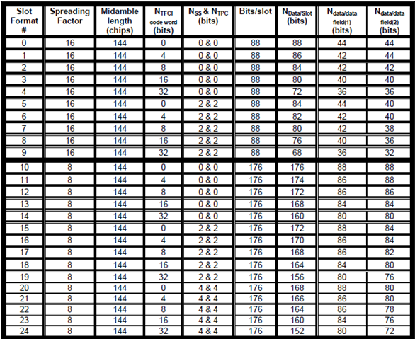
25.221 Table 8G, slot formats 0 to 24. At SF 16 a slot carries 88 bits, and at SF 8 it carries 176 bits.
Five TFCI sizes repeat in every block : 0, 4, 8, 16 and 32 bits. That is no TFCI, plus the four values that tfci-Coding can signal.SF 8 has a third SS and TPC size : slot formats 20 to 24 carry 4 and 4 bits, which is two symbols of each.
The second part holds slot formats 25 to 46. Slot formats 25 to 39 use SF 4, and slot formats 40 to 46 are the first rows with SF 2.
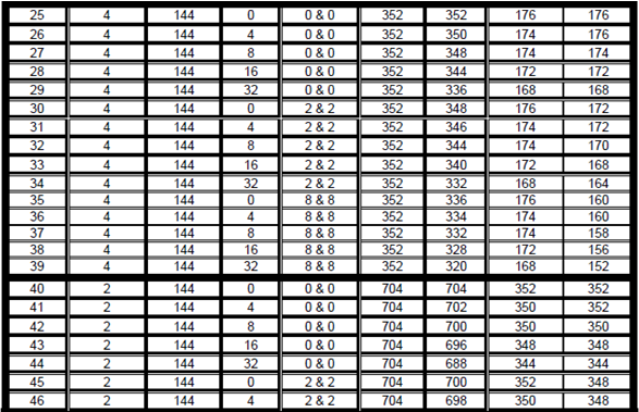
25.221 Table 8G, slot formats 25 to 46. Halving the SF doubles the bits per slot, to 352 bits at SF 4 and 704 bits at SF 2.
SF 4 carries up to 8 and 8 SS and TPC bits : slot formats 35 to 39, which is four symbols of each.
The third part holds slot formats 47 to 69. Slot formats 47 to 54 finish the SF 2 block, and slot formats 55 to 69 use SF 1.
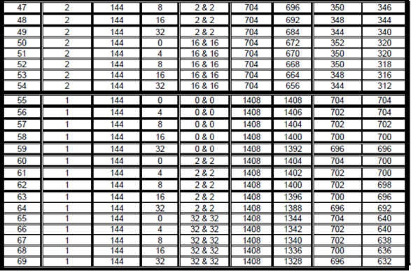
25.221 Table 8G, slot formats 47 to 69. SF 1 gives 1408 bits per slot, the same as the SF 1 rows of the downlink table.
The largest SS and TPC size grows as the SF falls : 16 and 16 bits at SF 2, and 32 and 32 bits at SF 1.The three images match the current table : the values agree with Table 8G in 25.221 v19.0.0, for all 70 slot formats.
You can rebuild any row with two rules. The data bits per slot are 2 x 352 / SF QPSK symbols, which is 2 x 352 / SF x 2 bits. One slot carries half of the TFCI code word, because the code word is split over the two sub-frames of a radio frame. So slot format 18, with SF 8, 16 TFCI bits and 2 and 2 SS and TPC bits, has 176 - 8 - 2 - 2 = 164 data bits.
Seventy slot formats come from three choices : five SFs, five TFCI sizes including none, and two or three SS and TPC sizes per SF.Bits per slot are fixed by the SF : 88, 176, 352, 704 and 1408 bits for SF 16, 8, 4, 2 and 1.A slot pays half of the TFCI code word : a 16-bit code word costs 8 bits of each slot that carries it.
How does the uplink table differ from the downlink table ?
The downlink table, 25.221 Table 8F, has only 25 rows, while Table 8G has 70. The two tables share the burst structure, so the difference comes from the spreading factors and from the SS and TPC sizes. The DL slot format page covers Table 8F.
The downlink of a dedicated channel uses only SF 16 or SF 1. The uplink allows SF 16, 8, 4, 2 and 1. A UE with one uplink code can therefore choose from five data rates per timeslot. The downlink changes its rate with the number of SF 16 codes, or with one SF 1 code, instead.
The SS and TPC column follows the IE ss-TPC-Symbols, with its values zero, one and sixteenOverSF. With QPSK, "one" means one symbol of 2 bits for SS and one for TPC, so it gives 2 and 2 bits at every SF. "sixteenOverSF" means 16/SF symbols. That is one symbol at SF 16, two at SF 8, four at SF 4, eight at SF 2 and sixteen at SF 1. This is where the rows with 4 and 4, 8 and 8, 16 and 16, and 32 and 32 bits come from. The downlink table has only SF 16 and SF 1, so it has only 2 and 2 and 32 and 32.
The meaning of the fields also differs by direction. An uplink TPC command controls the downlink power. An uplink slot still reserves space for SS symbols, but 25.221 notes that the uplink uses no SS symbol, and that the space is reserved for future use. This keeps the uplink and downlink slots in the same structure.
Five uplink SFs against two downlink SFs : that is the main reason for 70 rows against 25.sixteenOverSF scales with the SF : it gives 2 and 2 bits at SF 16 and up to 32 and 32 bits at SF 1.The uplink SS field is reserved : its bits are counted in the table, but the uplink carries no SS command in them.
Which slot format does a real uplink DPCH use ?
Let's apply the table to a real uplink DPCH. The HSDPA radio bearer page shows a tester decode of a RadioBearerSetup message, and its UL CCTrCH gives all the values we need. The method is the same as on the downlink page: each RRC field removes some rows of the table.
The UL CCTrCH of that message carries the following values in timeslot 1.
UL-TS-ChannelisationCode is cc2-1 : the code has SF 2, so only slot formats 40 to 54 remain.tfci-Existence is TRUE and tfci-Coding is tfci-bits-16 : the TFCI code word has 16 bits, so slot formats 43, 48 and 53 remain.ss-TPC-Symbols is one : this gives 2 and 2 bits, so slot format 48 remains.
Slot format 48 has 704 bits per slot and 692 data bits: 348 in the first data field and 344 in the second. If the same timeslot had used sixteenOverSF, the answer would be slot format 53, with 16 and 16 SS and TPC bits and only 664 data bits.
An uplink timeslot can also carry two codes, because UL-TS-ChannelisationCodeList has a size of 1 to 2. In that case the TFCI, SS and TPC go on the physical channel with the lowest physical channel sequence number. The second code then carries only data. So its slot format is the row without TFCI and without SS and TPC for its SF.
The uplink code gives the SF directly : unlike the downlink bitmap, the enumerated value cc2-1 names SF 2 and code 1.The same three filters apply in both directions : SF, TFCI code word size, and SS and TPC symbols.The HSDPA example uses slot format 48 : SF 2, 16 TFCI bits and 2 and 2 SS and TPC bits, with 692 data bits per slot.
Reference
- 25.221 Physical channels and mapping of transport channels onto physical channels TDD - v19.0.0, subclauses 5A.2.2 Burst format, 5A.2.2.1 to 5A.2.2.3 Transmission of TFCI, TPC and SS, and Table 8G
- 25.331 Radio Resource Control RRC protocol specification - v19.0.1, subclause 10.3.6.37 Individual timeslot info and the ASN.1 of UplinkTimeslotsCodes-LCR-r4 and UL-TS-ChannelisationCodeList