An E-TFCI is only a 7 bit index. The transport block size behind it depends on which table the UE uses, and 25.321 Annex B defines seven such tables for FDD. RRC chooses the table once, and the E-DPCCH carries the index in every TTI. This page shows where the table choice sits in the RRC message, which table each setting selects, and how the index then reaches the Node B.
E-TFCI Table Selection by RRC
How does the UE know which of the seven tables to use? Two RRC fields decide it together: the E-DCH TTI and the E-TFCI table index. The decoded message below shows both fields, and the arrows link each of them to the table name.
There are many different E-TFCI table specified in 25.321. Which table among those tables are used is determined by the RRC message (Radio Bearer Setup, RRC Connection Setup) as shown below.
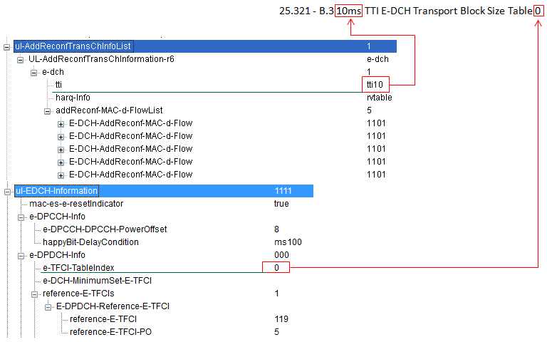
tti10 and e-TFCI-TableIndex 0 together select 25.321 Annex B.3, the 10ms TTI E-DCH Transport Block Size Table 0.
tti : sits in the e-dch entry of ul-AddReconfTransChInfoList. The value tti10 selects one of the 10 ms tables, and tti2 would select one of the 2 ms tables.e-TFCI-TableIndex : sits in e-DPDCH-Info under ul-EDCH-Information. The value 0 selects table 0 of the TTI in use.reference-E-TFCI 119 with reference-E-TFCI-PO 5 : the reference point for the E-DPDCH gain factor. In Annex B.3, E-TFCI 119 is a transport block of 14453 bits.e-DPCCH-DPCCH-PowerOffset 8 and happyBit-DelayCondition ms100 : set the E-DPCCH power and the happy bit timing. They do not affect the table choice.
The index field can only be 0 or 1, but there are five 2 ms tables. 25.331 clause 10.3.6.99 closes that gap with a note. When the UE operates in 16QAM mode, it adds 2 to the signalled index, so 0 and 1 become tables 2 and 3. When the UE operates in 64QAM mode, it uses table 4 whatever the index says. The table below lists all seven tables with their largest transport block.
TTI | Table | Selected when | 25.321 Annex | Largest TB size, bits | E-TFCI not used |
2 ms | 0 | index 0 | B.1 | 11484 | 120 |
2 ms | 1 | index 1 | B.2 | 11478 | 115 |
2 ms | 2 | index 0 in 16QAM mode | B.2a | 22995 | 121 |
2 ms | 3 | index 1 in 16QAM mode | B.2b | 22996 | 101, 102 |
2 ms | 4 | 64QAM mode, any index | B.2c | 34507 | - |
10 ms | 0 | index 0 | B.3 | 20000 | - |
10 ms | 1 | index 1 | B.4 | 19950 | - |
Every table starts at E-TFCI 0 with an 18 bit transport block. A few E-TFCIs in the 2 ms tables have no transport block size, marked N/A in 25.321, and 25.321 clause 11.8.1.4 forbids the UE to select them. The 10 ms table 0 ends at 20000 bits, which is the 10 ms limit of E-DCH categories 4 to 7 in 25.306.
E-DPDCH Info in 25.331
The e-DPDCH-Info block in the capture follows the E-DPDCH-Info IE of 25.331. The listing below shows the original structure with the table index as its first field.
Following is based on
E-DPDCH-Info ::=                    SEQUENCE {
    e-TFCI-TableIndex                   E-TFCI-TableIndex,
    e-DCH-MinimumSet-E-TFCI             E-DCH-MinimumSet-E-TFCI             OPTIONAL,
    reference-E-TFCIs                   E-DPDCH-Reference-E-TFCIList,
    maxChannelisationCodes              E-DPDCH-MaxChannelisationCodes,
    pl-NonMax                           E-DPDCH-PL-NonMax,
    schedulingInfoConfiguration         E-DPDCH-SchedulingInfoConfiguration,
    threeIndexStepThreshold             INTEGER (0..37)                     OPTIONAL,
    twoIndexStepThreshold               INTEGER (0..37)                     OPTIONAL
}

E-TFCI-TableIndex ::=               INTEGER (0..1)
E-DPDCH-Info-r7 and E-DPDCH-Info-r8 keep e-TFCI-TableIndex as the first field and the same INTEGER (0..1) range. They extend the reference E-TFCI list, and the -r8 version adds minReduced-E-DPDCH-GainFactor. So the table selection works in the same way in every release.
Two fields choose the table : the E-DCH TTI and e-TFCI-TableIndex.The modulation mode shifts the table : 16QAM adds 2 to the index, and 64QAM always uses table 4.Some E-TFCIs are never used : the N/A entries of the 2 ms tables 0 to 3.
E-TFCI Value in Each TTI
The table is fixed by RRC, but the index changes from one TTI to the next. The UE picks the index in every TTI and reports it, so the Node B never has to guess the transport block size.
Which specific E-TFCI value is used at a specified TTI ? It is specified in E-DPCCH which is transmitted by UE.
The E-DPCCH carries 10 bits in each TTI: the 7 bit E-TFCI, the 2 bit retransmission sequence number RSN, and the happy bit. The Node B decodes E-DPCCH first. It reads the E-TFCI and looks up the transport block size in the configured table, and only then decodes E-DPDCH. The 7 bit field covers the values 0 to 127, which matches the 128 entries of the largest tables.
The UE chooses the value with the E-TFC selection procedure of 25.321, which the E-TFCI Selection page describes. Let's apply it to the configuration in the capture. With the 10 ms Table 0, E-TFCI 127 means 20000 bits in 10 ms, the largest block of the table. E-TFCI 119 means 14453 bits, and the RRC message uses this value as its reference E-TFCI. The UE selects a smaller index when its power, its grant or its buffer does not support the larger one.
RRC fixes the table, the UE picks the index : the table stays for the whole configuration, and the index can change in every TTI.E-DPCCH carries the index : 7 bits of E-TFCI next to the RSN and the happy bit.The Node B needs E-DPCCH first : without the E-TFCI it cannot know the transport block size on E-DPDCH.
Reference
[1] 3GPP TS 25.321 v19.0.0 - clause 9.2.5.4, Transport block size, clause 11.8.1.4, E-TFC Selection, and Annex B
[2] 3GPP TS 25.331 v19.0.1 - clause 10.3.6.99, E-DPDCH Info, and the ASN.1 of clause 11.3
[3] 3GPP TS 25.212 v19.0.0 - clause 4.9, Coding for E-DPCCH
[4] 3GPP TS 25.306 v19.0.0 - Table 5.1g, FDD E-DCH physical layer categories