An RF connector joins two pieces of transmission line, and it has to do that without disturbing the signal. So a connector is really a short piece of coaxial line with a mechanical coupling built around it. Its size, its dielectric and its impedance decide how high in frequency it can go. On this page I'll start from the common structure, then go through the connector types and their frequency limits. Finally I'll show with two formulas why a smaller connector reaches a higher frequency.
- What Is the Common Structure of an RF Connector?
- Which Connector Types Are Common, and How High Can Each Go?
- Why Does a Smaller Connector Reach a Higher Frequency?
What Is the Common Structure of an RF Connector?
A catalog lists dozens of connector names, and at first they look unrelated. But electrically every coaxial connector is built from the same three parts. Once you know those three parts, you can compare any two connectors by asking the same three questions.
Even though there so many different types and variations of RF or mmWave connectors, they can be represented in a common structure as illustrated below. A type of connector is determined depending on the factors represented as questions below.
The drawing below is a cross section of a coaxial line. It shows the center conductor, the dielectric around it and the outer conductor, which also works as the shield. Each part carries one design question, written next to it.
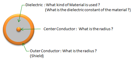
Figure 1. Cross section of a coaxial connector. Two radii and one dielectric constant fix both the characteristic impedance and the highest usable frequency.
The center conductor carries the signal : the drawing asks for its radius. In the impedance formula further down this page, its diameter is d. In a mated pair it is the pin on one side and the socket on the other.The dielectric fills the space between the conductors : it also holds the center conductor in place. The drawing asks for its dielectric constant, because the dielectric constant changes both the impedance and the speed of the wave. The Dielectric page explains the dielectric constant in more detail.The outer conductor is the shield and the return path : the drawing asks for its radius as well. Its inner diameter is D in the impedance formula. The coupling nut or the snap-on body is built around it.The three answers describe the line inside the connector : two connectors with the same radii and the same dielectric behave as the same coaxial line, even when their coupling mechanics differ.
Which Connector Types Are Common, and How High Can Each Go?
The table below lists common coaxial connector types in order of their maximum frequency. For each type it gives the maximum frequency and the dielectric, and three rows carry a photo of the connector. Read the Max Freq column as a rated upper limit. It is not a frequency where the connector suddenly stops working.
|
Connector type |
Max Freq |
Dielectric |
Image |
Comments |
|
BNC |
4 GHz |
PTFE |
|
|
|
SMB |
4 GHz |
PTFE |
|
|
|
OSMT |
6 GHz |
PTFE |
|
|
|
OSX, MCX, PCX |
6 GHz |
PTFE |
|
|
|
MMCX |
|
PTFE |
|
|
|
SMC |
10 GHz |
PTFE |
|
|
|
25 GHz |
PTFE |
|
||
|
TNC |
15 GHz |
PTFE |
|
|
|
N |
11 GHz/18 GHz |
PTFE |
|
|
|
APC-7, 7 mm |
18 GHz |
PTFE |
|
|
|
OSP |
22 GHz |
PTFE |
|
|
|
3.5 mm |
26.5 GHz |
Air |
|
|
|
OSSP |
28 GHz |
PTFE |
|
|
|
SSMA |
38 GHz |
PTFE |
|
|
|
2.92 mm |
40 GHz |
Air |
|
|
|
40 GHz |
Air |
|
||
|
GPO, OSMP, SMP |
40 GHz |
PTFE |
|
|
|
OS-50P |
40 GHz |
|
|
|
|
2.4 mm |
50 GHz |
Air |
|
|
|
1.85 mm |
60 GHz |
Air |
|
|
|
60 GHz |
Air |
|
||
|
1 mm |
110 GHz |
Air |
|
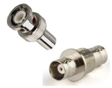
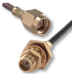
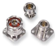
The photos show three of the most widely used families. The BNC row shows a plug and a jack with the bayonet coupling. The SMA row shows a cable plug and a bulkhead jack, both with a threaded coupling. The N row shows three flange-mount and bulkhead jacks, which are much larger than the SMA.
Now let's look at the pattern in the table. Every type up to 22 GHz uses PTFE as the dielectric. Above that the table mixes the two. The precision types that are named by a diameter, 3.5 mm, 2.92 mm, 2.4 mm, 1.85 mm and 1 mm, use air. The small subminiature and snap-on types such as OSSP, SSMA and GPO keep PTFE. The diameter in those names is the inner diameter of the outer conductor, and the maximum frequency rises as that diameter goes down. The next section shows why.
Some rows describe the same interface under two names. K is a trade name for the 2.92 mm connector, and V is a trade name for the 1.85 mm connector. So the table gives K the same 40 GHz and air dielectric as 2.92 mm, and V the same 60 GHz and air dielectric as 1.85 mm.
Several families are also designed to mate with each other mechanically. The 3.5 mm and 2.92 mm connectors mate with SMA, and the 1.85 mm connector mates with 2.4 mm. This lets you use one precision cable with several kinds of device port. But a mated pair performs no better than its weaker connector, so an SMA plugged into a 2.92 mm port is still an SMA connection. Also, an SMA is made to looser tolerances than a precision connector, and a bad SMA pin can damage a precision port. This is why many labs keep a connector saver on an expensive instrument port.
Max Freq rises as the connector gets smaller : BNC and SMB stop at 4 GHz, SMA reaches 25 GHz and the 1 mm connector reaches 110 GHz.The precision types from 3.5 mm upward use air : the subminiature and snap-on types at similar frequencies keep PTFE.Two names can mean one connector : K is the 2.92 mm interface and V is the 1.85 mm interface, so their rows match.A mated pair is limited by its weaker connector : mechanical compatibility does not carry the rating of the better connector across the joint.
Why Does a Smaller Connector Reach a Higher Frequency?
A connector is a short coaxial line, so its limits are the limits of a coaxial line. Two conditions limit the design. The line has to stay at 50 ohm, and it has to carry only one propagation mode. Let's put numbers on both conditions and see what is left to choose.
I'll start with the impedance. Take a coaxial line whose outer conductor has the inner diameter D and whose center conductor has the diameter d. The space between them is filled with a dielectric of relative dielectric constant εr. The characteristic impedance of this line is
Z0 = ( 60 / √εr ) x ln( D / d )
For air, εr = 1, so 50 ohm needs ln(D/d) = 50/60 and D/d = 2.30. For PTFE, εr is about 2.1, so 50 ohm needs D/d = 3.35. This means the ratio D/d is fixed as soon as you pick the impedance and the dielectric. The only free choice left is the absolute size of the line.
Next comes the frequency limit. A coaxial line carries the TEM mode at any frequency. But above a cutoff frequency it can also carry its first waveguide mode, TE11. Once TE11 can propagate, every discontinuity converts part of the signal into it. The insertion loss and the return loss then show sharp resonances. A good approximation of the TE11 cutoff is the frequency where the wavelength in the dielectric equals the mean circumference of the line:
fc = c / ( π x √εr x ( D + d ) / 2 )
Because D/d is already fixed, fc is inversely proportional to D. If you halve the connector, you double the cutoff. The table below applies the two formulas to the air-dielectric sizes in the connector table. The column d is computed from D/d = 2.30. The exact column solves the Bessel function equation of the TE11 mode instead of using the approximation.
Connector |
D, mm |
d for 50 ohm, mm |
TE11 cutoff, approximation, GHz |
TE11 cutoff, exact, GHz |
Max Freq in the table, GHz |
APC-7, 7 mm |
7.0 |
3.04 |
19.0 |
19.4 |
18 |
3.5 mm |
3.5 |
1.52 |
38.0 |
38.8 |
26.5 |
2.92 mm, K |
2.92 |
1.27 |
45.6 |
46.5 |
40 |
2.4 mm |
2.4 |
1.04 |
55.4 |
56.6 |
50 |
1.85 mm, V |
1.85 |
0.80 |
71.9 |
73.4 |
60 |
1 mm |
1.0 |
0.43 |
133.0 |
135.8 |
110 |
Every rated Max Freq sits below the computed cutoff, and the reason is that a real connector is not an ideal line. The dielectric support bead lowers the local cutoff, because the cutoff falls with √εr. The slots in the socket contacts and the manufacturing tolerances add discontinuities, and those couple energy into TE11 once it can propagate. So the rating keeps a margin below the ideal cutoff. The 3.5 mm connector keeps the largest margin in the table, 26.5 GHz against 38.8 GHz.
The dielectric has a cost as well. Let's fill a line with the same 3.5 mm outer diameter with PTFE instead of air. The 50 ohm condition now needs d = 3.5 / 3.35 = 1.05 mm, and the exact TE11 cutoff drops to about 29.8 GHz, against 38.8 GHz for air. So a PTFE-filled connector has to be smaller than an air connector to reach the same frequency. This is one reason why the precision types from 3.5 mm upward use air.
The impedance fixes the ratio D/d : 50 ohm needs D/d = 2.30 in air and about 3.35 in PTFE.The size fixes the cutoff : fc scales as 1/D, so the 1 mm line reaches about 3.5 times the cutoff of the 3.5 mm line.A dielectric lowers the cutoff : with the same 3.5 mm outer diameter, PTFE moves the TE11 cutoff from 38.8 GHz down to about 29.8 GHz.The rated Max Freq keeps a margin : beads, contact slots and tolerances make a real connector less ideal than the line it is built from, so the rating stays below the ideal TE11 cutoff.