|
5G Frame Structure in Detail
There has been long long discussions on frame structure both in academia and in 3GPP and now we have pretty clear agreements on what a NR(5G) radio frame would look like. In this page, I will describe on NR Frame Structure that is specified in 3GPP specification (38.211). If you are intrested in those long discussions and histories about show these specification came out for your personalinterests and study, refer to 5G Frame Structure Candidate page.
5G Frame structure
5G brings with it not only faster data rates and lower latency but also an entirely new frame structure to better handle the diverse range of wireless devices and applications we use today. This note will talk about the intricacies of the 5G frame structure and how it enables the seamless functioning of our ever-increasingly interconnected world.
First, it's crucial to understand that the 5G frame structure has been designed to be more flexible than its predecessors LTE in order to meet the demanding requirements of modern applications like autonomous vehicles, Internet of Things (IoT), and high-speed video streaming. Instead of sticking to a rigid design, the 5G frame structure adapts according to the needs of each application, making the entire network more efficient.
One key aspect of this flexible 5G frame structure is its time-frequency resources allocation method. The time frequency resources is divided into resource blocks and further subdivided into resource grid elements. This ensures an optimal distribution of network resources, delivering faster, uninterrupted connectivity to users. The network identifies and meets diverse connectivity needs, providing a high-speed connection for streaming a 4K video while simultaneously ensuring the low-latency connection needed for an autonomous vehicle.
Furthermore, the 5G frame structure is based on a slot and symbol-based design. This means the 5G network can dynamically adjust the duration of each time slot based on the service's needs. A data-heavy service might get longer slots, while services needing quick response times, like remote surgery or smart factories, might be allocated shorter slots. This flexibility improves the efficiency and responsiveness of the 5G network.
Then comes the 5G mini-slot concept. Mini-slots allow the 5G frame structure to provide faster response times for certain applications. In an emergency situation, where a fraction of a second can make a significant difference, the deployment of a mini-slot can ensure the prompt delivery of vital information. (NOTE : The details on Mini Slot is written in a separate note here).
Lastly, the 5G frame structure includes both self-contained and non-self-contained subframes. This feature adds another layer of flexibility, allowing different data transmission methods based on the specific requirements of the application, thereby maintaining the quality of service and reducing latency further.
The innovative design of the 5G frame structure is pivotal in unlocking the full potential of 5G technology. By providing a flexible, adaptable, and efficient way of managing network resources, it lays the groundwork for a truly interconnected future. This dynamic approach of the 5G frame structure has ushered in a new era of wireless technology, ensuring superior performance that caters to the diverse needs of modern digital society.
At the heart of various flexbility described above is the concept called Numerology. The major topics of this note is about the defnition of nemeroalogy and how each numerogy is related to physical properties of time and frequency domain resource allocation.
Numerology - Subcarrier Spacing
Numerology refers to the set of parameters that define the physical layer structure, specifically, the subcarrier spacing, symbol duration, and cyclic prefix length in an OFDM system.
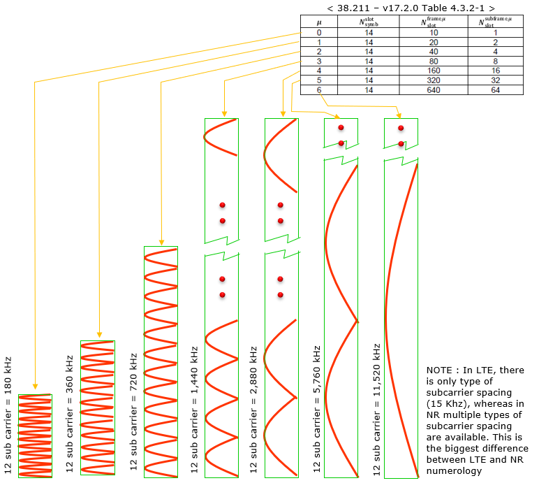
Comparing to LTE numberology (subcarrier spacing and symbol length), the most outstanding diffrence you can notice is thet NR support multiple different types of subcarrier spacing (in LTE there is only one type of subcarrier spacing, 15 Khz). The types NR numerology is summarized in 38.211 and I converted the table into illustration to give you intuitive understanding of these numerology.
As you see here, each numerology is labled as a parameter(u, mu in Greek). The numerology (u = 0) represents 15 kHz which is same as LTE. And as you see in the second column the subcarrier spacing of other u is derived from (u=0) by scaling up in the power of 2.
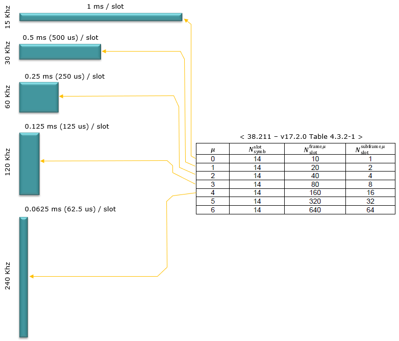
Numerology and Slot Length
As illustrated below, Slot length gets different depending on numerology. The general tendancy is that slot length gets shorter as subcarrier spacing gets wider. Actually this tendancy comes from the nature of OFDM. You would see further details on how the slot length is derived in Radio Frame Structure section.
Numerology and Supported Channels
Not every numerology can be used for every physical channel and signals. That is, there is a specific numerologies that are used only for a certain type of physical channels even though majority of the numerologies can be used any type of physical channels. Following table shows which numerologies can be used for which physical channels.
< 38.300-Table 5.1-1: Supported transmission numerologies and additional info.>
|
Numerology |
Subcarrier Spacing (kHz) |
CP type |
Supported for Data (PDSCH, PUSCH etc) |
Supported for Sync (PSS,SSS,PBCH) |
PRACH |
|
N/A |
1.25 |
No |
No |
Long Preamble |
|
|
N/A |
5 |
No |
No |
Long Preamble |
|
|
0 |
15 |
Normal |
Yes |
Yes |
Short Preamble |
|
1 |
30 |
Normal |
Yes |
Yes |
Short Preamble |
|
2 |
60 |
Normal,Extended |
Yes |
No |
Short Preamble |
|
3 |
120 |
Normal |
Yes |
Yes |
Short Preamble |
|
4 |
240 |
Normal |
No |
Yes |
|
|
5 |
480 |
Normal |
Yes |
Yes |
|
|
6 |
960 |
Normal |
Yes |
Yes |
OFDM Symbol Duration
The table shown below is outlining key parameters of the 5G network's physical layer frame structure for different numerologies (denoted by μ). The numerology in 5G is used to define these parameters, and includes the subcarrier spacing, the OFDM symbol duration, the cyclic prefix duration, and the total duration of the OFDM symbol including the cyclic prefix.
The numerology values range from 0 to 4, corresponding to subcarrier spacings of 15, 30, 60, 120, and 240 kHz respectively. A larger numerology indicates a wider subcarrier spacing. As the numerology increases, the OFDM symbol duration and the cyclic prefix duration decrease, resulting in a shorter overall OFDM symbol duration (including the cyclic prefix).
|
Parameter / Numerlogy (u) |
0 |
1 |
2 |
3 |
4 |
|
Subcarrier Spacing (Khz) |
15 |
30 |
60 |
120 |
240 |
|
OFDM Symbol Duration (us) |
66.67 |
33.33 |
16.67 |
8.33 |
4.17 |
|
Cyclic Prefix Duration (us) |
4.69 |
2.34 |
1.17 |
0.57 |
0.29 |
|
OFDM Symbol including CP (us) |
71.35 |
35.68 |
17.84 |
8.92 |
4.46 |
Numerology - Sampling Time
Sampling time can be defined differently depending on Numerogy (i.e, Subcarrier Spacing) and in most case two types of Timing Unit Tc and Ts are used.
- Tc = 0.509 ns
- Ts = 32.552 ns
See Physial Layer Timing Unit page to see how these numbers are derived and to see some other timing units.
Radio Frame Structure
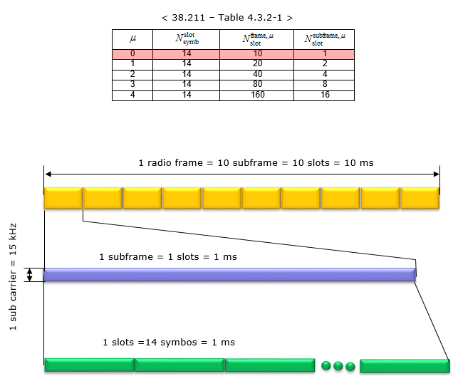
As described above, in 5G/NR multiple numerologies(waveform configuration like subframe spacing) are supported and the radio frame structure gets a little bit different depending on the type of the numerology. However, regardless of numerology the length of one radio frame and the length of one subfame is same. The length of a Radio Frame is always 10 ms and the length of a subframe is always 1 ms.
Then what should get different to accomondate the physical property of the different numerology ? The anwer is to put different number of slots within one subfame. There is another varying parameter with numerology. It is the number of symbols within a slot. However, the number of symbols within a slot does not change with the numberology, it only changes with slot configuration type. For slot with normal CP(Cyclic Prefix), the number of symbols for a slot is always 14 and for slot with extended CP, the number of symbols for a slot is always 12.
Summarizing this in bullets :
- Regardless of the numerology, the length of one radio frame (10 ms) and one subframe (1 ms) remains consistent.
- Accommodation for the physical properties of different numerologies is achieved by varying the number of slots within one subframe.
- Slots with a normal Cyclic Prefix (CP) always contain 14 symbols, while slots with an extended CP always contain 12 symbols.
Now let's look into the details of radio frame structure for each numerology and slot configuration.
< Normal CP, Numerology = 0 >
In this configuration, a subframe has only one slot in it, it means a radio frame contains 10 slots in it. The number of OFDM symbols within a slot is 14.
< Normal CP, Numerology = 1 >
In this configuration, a subframe has 2 slots in it, it means a radio frame contains 20 slots in it. The number of OFDM symbols within a slot is 14.

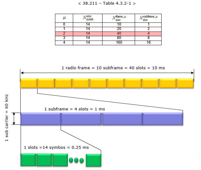
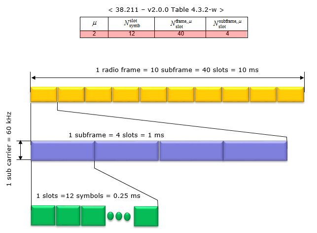
< Normal CP, Numerology = 2 >
In this configuration, a subframe has 4 slots in it, it means a radio frame contains 40 slots in it. The number of OFDM symbols within a slot is 14.
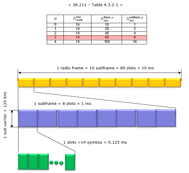
< Normal CP, Numerology = 3 >
In this configuration, a subframe has 8 slots in it, it means a radio frame contains 80 slots in it. The number of OFDM symbols within a slot is 14.
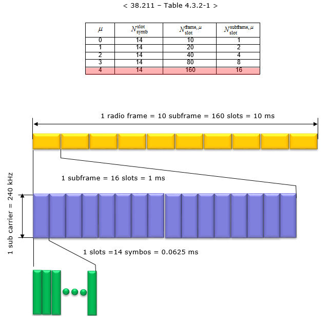
< Normal CP, Numerology = 4 >
In this configuration, a subframe has 16 slots in it, it means a radio frame contains 160 slots in it. The number of OFDM symbols within a slot is 14.
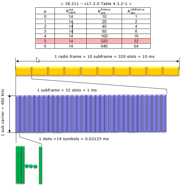
< Normal CP, Numerology = 5 >
In this configuration, a subframe has 32 slots in it, it means a radio frame contains 320 slots in it. The number of OFDM symbols within a slot is 14.
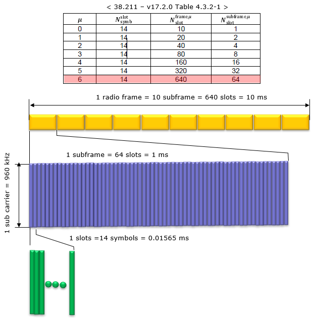
< Normal CP, Numerology = 6 >
In this configuration, a subframe has 64 slots in it, it means a radio frame contains 640 slots in it. The number of OFDM symbols within a slot is 14.
< Extended CP, Numerology = 2 >
In this configuration, a subframe has 4 slots in it, it means a radio frame contains 40 slots in it. The number of OFDM symbols within a slot is 12.
Slot Format
Slot Format indicates how each of symbols within a single slot is used. It defines which symbols are used for uplink and which symbols are used for downlink within a specific slot. In LTE TDD, if a subframe (equivalent to a Slot in NR) is configured for DL or UL, all of the symbols within the subframe should be used as DL or UL. But in NR, the symbols within a slot can be configured in various ways as follows.
- We don't need to use every symbols within a slot (this can be a similar concept in LAA subframe where only a part of subframes can be used for data transmission).
- Single slot can be devided into multiple segments of consecutive symbols that can be used for DL , UL or Flexible.
Theoretically we can think of almost infinite number of possible combinations of DL symbol, UL symbol, Flexible Symbol within a slot, but 3GPP allows only 61 predefined symbol combination within a slot as in following table. These predefined symbol allocation of a slot called Slot Format. (For the details on how these Slot Format is being used in real operation, refer to Slot Format Combination page).
<38.213 v15.7 -Table 11.1.1-1: Slot formats for normal cyclic prefix>
D : Downlink, U : Uplink, F : Flexible
|
|
Symbol Number in a slot |
|||||||||||||
|
Format |
0 |
1 |
2 |
3 |
4 |
5 |
6 |
7 |
8 |
9 |
10 |
11 |
12 |
13 |
|
0 |
D |
D |
D |
D |
D |
D |
D |
D |
D |
D |
D |
D |
D |
D |
|
1 |
U |
U |
U |
U |
U |
U |
U |
U |
U |
U |
U |
U |
U |
U |
|
2 |
F |
F |
F |
F |
F |
F |
F |
F |
F |
F |
F |
F |
F |
F |
|
3 |
D |
D |
D |
D |
D |
D |
D |
D |
D |
D |
D |
D |
D |
F |
|
4 |
D |
D |
D |
D |
D |
D |
D |
D |
D |
D |
D |
D |
F |
F |
|
5 |
D |
D |
D |
D |
D |
D |
D |
D |
D |
D |
D |
F |
F |
F |
|
6 |
D |
D |
D |
D |
D |
D |
D |
D |
D |
D |
F |
F |
F |
F |
|
7 |
D |
D |
D |
D |
D |
D |
D |
D |
D |
F |
F |
F |
F |
F |
|
8 |
F |
F |
F |
F |
F |
F |
F |
F |
F |
F |
F |
F |
F |
U |
|
9 |
F |
F |
F |
F |
F |
F |
F |
F |
F |
F |
F |
F |
U |
U |
|
10 |
F |
U |
U |
U |
U |
U |
U |
U |
U |
U |
U |
U |
U |
U |
|
11 |
F |
F |
U |
U |
U |
U |
U |
U |
U |
U |
U |
U |
U |
U |
|
12 |
F |
F |
F |
U |
U |
U |
U |
U |
U |
U |
U |
U |
U |
U |
|
13 |
F |
F |
F |
F |
U |
U |
U |
U |
U |
U |
U |
U |
U |
U |
|
14 |
F |
F |
F |
F |
F |
U |
U |
U |
U |
U |
U |
U |
U |
U |
|
15 |
F |
F |
F |
F |
F |
F |
U |
U |
U |
U |
U |
U |
U |
U |
|
16 |
D |
F |
F |
F |
F |
F |
F |
F |
F |
F |
F |
F |
F |
F |
|
17 |
D |
D |
F |
F |
F |
F |
F |
F |
F |
F |
F |
F |
F |
F |
|
18 |
D |
D |
D |
F |
F |
F |
F |
F |
F |
F |
F |
F |
F |
F |
|
19 |
D |
F |
F |
F |
F |
F |
F |
F |
F |
F |
F |
F |
F |
U |
|
20 |
D |
D |
F |
F |
F |
F |
F |
F |
F |
F |
F |
F |
F |
U |
|
21 |
D |
D |
D |
F |
F |
F |
F |
F |
F |
F |
F |
F |
F |
U |
|
22 |
D |
F |
F |
F |
F |
F |
F |
F |
F |
F |
F |
F |
U |
U |
|
23 |
D |
D |
F |
F |
F |
F |
F |
F |
F |
F |
F |
F |
U |
U |
|
24 |
D |
D |
D |
F |
F |
F |
F |
F |
F |
F |
F |
F |
U |
U |
|
25 |
D |
F |
F |
F |
F |
F |
F |
F |
F |
F |
F |
U |
U |
U |
|
26 |
D |
D |
F |
F |
F |
F |
F |
F |
F |
F |
F |
U |
U |
U |
|
27 |
D |
D |
D |
F |
F |
F |
F |
F |
F |
F |
F |
U |
U |
U |
|
28 |
D |
D |
D |
D |
D |
D |
D |
D |
D |
D |
D |
D |
F |
U |
|
29 |
D |
D |
D |
D |
D |
D |
D |
D |
D |
D |
D |
F |
F |
U |
|
30 |
D |
D |
D |
D |
D |
D |
D |
D |
D |
D |
F |
F |
F |
U |
|
31 |
D |
D |
D |
D |
D |
D |
D |
D |
D |
D |
D |
F |
U |
U |
|
32 |
D |
D |
D |
D |
D |
D |
D |
D |
D |
D |
F |
F |
U |
U |
|
33 |
D |
D |
D |
D |
D |
D |
D |
D |
D |
F |
F |
F |
U |
U |
|
34 |
D |
F |
U |
U |
U |
U |
U |
U |
U |
U |
U |
U |
U |
U |
|
35 |
D |
D |
F |
U |
U |
U |
U |
U |
U |
U |
U |
U |
U |
U |
|
36 |
D |
D |
D |
F |
U |
U |
U |
U |
U |
U |
U |
U |
U |
U |
|
37 |
D |
F |
F |
U |
U |
U |
U |
U |
U |
U |
U |
U |
U |
U |
|
38 |
D |
D |
F |
F |
U |
U |
U |
U |
U |
U |
U |
U |
U |
U |
|
39 |
D |
D |
D |
F |
F |
U |
U |
U |
U |
U |
U |
U |
U |
U |
|
40 |
D |
F |
F |
F |
U |
U |
U |
U |
U |
U |
U |
U |
U |
U |
|
41 |
D |
D |
F |
F |
F |
U |
U |
U |
U |
U |
U |
U |
U |
U |
|
42 |
D |
D |
D |
F |
F |
F |
U |
U |
U |
U |
U |
U |
U |
U |
|
43 |
D |
D |
D |
D |
D |
D |
D |
D |
D |
F |
F |
F |
F |
U |
|
44 |
D |
D |
D |
D |
D |
D |
F |
F |
F |
F |
F |
F |
U |
U |
|
45 |
D |
D |
D |
D |
D |
D |
F |
F |
U |
U |
U |
U |
U |
U |
|
46 |
D |
D |
D |
D |
D |
F |
U |
D |
D |
D |
D |
D |
F |
U |
|
47 |
D |
D |
F |
U |
U |
U |
U |
D |
D |
F |
U |
U |
U |
U |
|
48 |
D |
F |
U |
U |
U |
U |
U |
D |
F |
U |
U |
U |
U |
U |
|
49 |
D |
D |
D |
D |
F |
F |
U |
D |
D |
D |
D |
F |
F |
U |
|
50 |
D |
D |
F |
F |
U |
U |
U |
D |
D |
F |
F |
U |
U |
U |
|
51 |
D |
F |
F |
U |
U |
U |
U |
D |
F |
F |
U |
U |
U |
U |
|
52 |
D |
F |
F |
F |
F |
F |
U |
D |
F |
F |
F |
F |
F |
U |
|
53 |
D |
D |
F |
F |
F |
F |
U |
D |
D |
F |
F |
F |
F |
U |
|
54 |
F |
F |
F |
F |
F |
F |
f |
D |
D |
D |
D |
D |
D |
D |
|
55 |
D |
D |
F |
F |
F |
U |
U |
U |
D |
D |
D |
D |
D |
D |
|
62-254 |
Reserved |
|||||||||||||
|
255 |
UE determines the slot format for the slot based on tdd-UL-DL-ConfigurationCommon, or tdd-ULDL- ConfigurationDedicated and, if any, on detected DCI formats |
|||||||||||||
Why we need so many different types of slot formats ? Obviously it is not just to make your job difficult :). It is to make NR scheduling flexible especially for TDD operation. By applying a slot format or combining different slot formats in sequence, we can implement various different types of scheduling as in the following example (these examples are based on 5G NEW RADIO : Designing For The Future (Ericsson Technology Review))
|
DL-heavy transmission with UL part |
|||||||||||||||||||||||||||
|
Slot (e.g, slot format 28) |
Slot(e.g, slot format 28) |
||||||||||||||||||||||||||
|
D |
D |
D |
D |
D |
D |
D |
D |
D |
D |
D |
D |
F |
U |
D |
D |
D |
D |
D |
D |
D |
D |
D |
D |
D |
D |
F |
U |
|
UL-heavy transmission with DL Control |
|||||||||||||||||||||||||||
|
Slot(e.g, slot format 34) |
Slot(e.g, slot format 34) |
||||||||||||||||||||||||||
|
D |
F |
U |
U |
U |
U |
U |
U |
U |
U |
U |
U |
U |
U |
D |
F |
U |
U |
U |
U |
U |
U |
U |
U |
U |
U |
U |
U |
|
Slot aggregation for DL-heavy transmission (e.g, for eMBB) |
|||||||||||||||||||||||||||
|
Slot(e.g, slot format 0) |
Slot (e.g, slot format 28) |
||||||||||||||||||||||||||
|
D |
D |
D |
D |
D |
D |
D |
D |
D |
D |
D |
D |
D |
D |
D |
D |
D |
D |
D |
D |
D |
D |
D |
D |
D |
D |
F |
U |
|
Slot aggregation for UL-heavy transmission (e.g, for eMBB) |
|||||||||||||||||||||||||||
|
Slot |
Slot |
||||||||||||||||||||||||||
|
D |
F |
U |
U |
U |
U |
U |
U |
U |
U |
U |
U |
U |
U |
D |
U |
U |
U |
U |
U |
U |
U |
U |
U |
U |
U |
U |
U |
TDD DL/UL Common Configuration
See TDD DL/UL Common Configuration page.
Resource Grid
The resource grid for NR is defined as follows. If you just take a look at the picture, you would think it is almost identical to LTE resource grid. But the physical dimmension (i.e, subcarrier spacing, number of OFDM symbols within a radio frame) varies in NR depending on numerology.
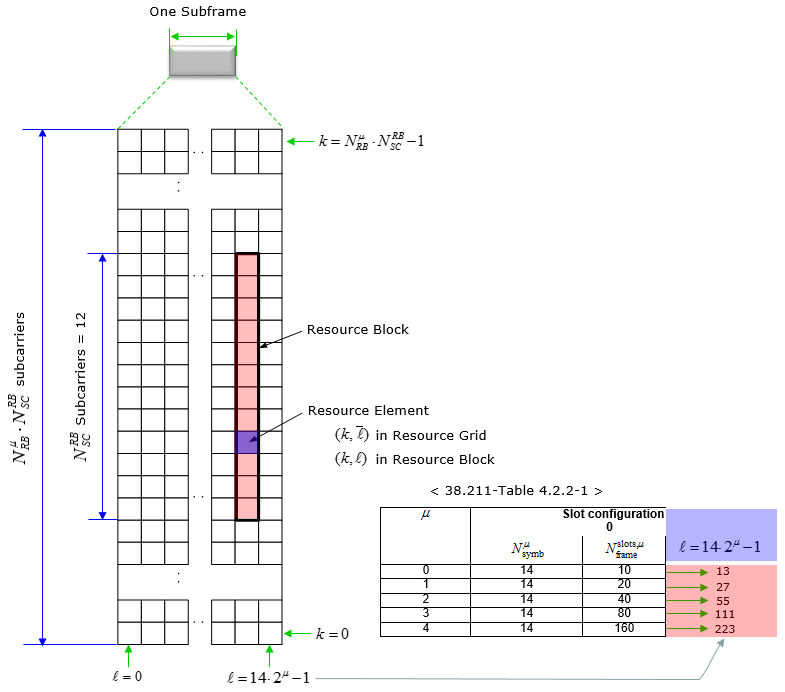
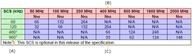
The maximum number of Resource blocks for downlink and uplink is defined as below (this is different from LTE). Following is the maximum number of RBs you can configure in RRC message and DCI. In terms of RF, you may need a little bit wider bandwidth than this because you need to consider the guardband. Refer to this page for estimating RF spectrum (RF bandwidth).
< 38.101-1 v17.6 : Table 5.3.2-1: Maximum transmission bandwidth configuration NRB : FR1 >
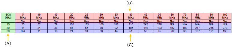
< 38.101-2 v17.6 - Table 5.3.2-1: Maximum transmission bandwidth configuration NRB : FR2 >
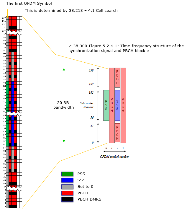
SS/PBCH
SS(PSS and SSS) and PBCH in NR is transmitted in the same 4 symbol block as specified in the following table.
< Frequency Domain Resource Allocation >
Overall description on the resource allocation for SS/PBCH block is described in 38.211 - 7.4.3.1 Time-frequency structure of an SS/PBCH block and followings are the summary of the specification.
- SS/PBCH block consists of 240 contiguous subcarriers (20 RBs)
- The subcarriers are numbered in increasing order from 0 to 239 within the SS/PBCH block
- The UE may assume that the contents(value) of the resource elements denoted as 'Set to 0' in Table 7.4.3.1-1 are set to zero. (This mean that the contents of the gray colored resource element in the SSB diagram shown below is filled with zeros).
- k_ssb corresponds to the gap between Subcarrier 0 of SS/PBCH block and Common Resource Block

- is obtained from the higher-layer parameter OffsetToPointA
- offset-ref-low-scs-ref-PRB corresponds to the FrequencyInfoDL.absoluteFrequencyPointA. Data type is ARFCN-ValueNR and the range of the value is INTEGER (0..3279165) in integer.
- There are two types of SS/PBCH Block
- Type A (Sub 6)
- k_ssb(k0 in older spec) = {0,1,2,...,23}
- 4 LSB bits of k_ssb value can informed to UE via ssb-subcarrierOffset in MIB
-
The MSB bit is informed to UE via a bit within the PBCH Data (
 )
)
- is expressed in terms of 15 Khz subcarrier spacing
- u (numerology) = {0,1}, FR1 (sub 6 Ghz)
- is expressed in terms of 15 Khz subcarrier spacing
- Type B (mmWave)
- k_ssb(k0 in older spec) = {0,1,2,...,11}
- the whole k_ssb value can be informed to UE via ssb-subcarrierOffset in MIB
- is expressed in terms of the subcarrier spacing provided by the higher-layer parameter subCarrierSpacingCommon in MIB .
- u (numerology) = {3,4}, FR2 (mmWave)
- is expressed in terms of 60 Khz subcarrier spacing
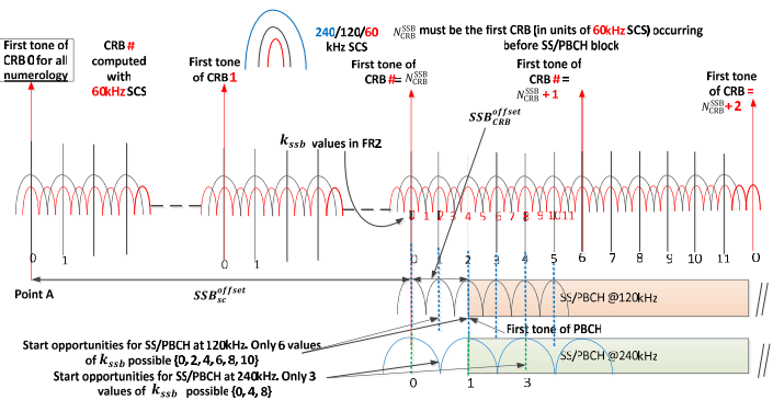
NOTE : Actually understanding k_ssb and ![]() in the resource grid often get confusing and hard to visualize. One of Sharetechnote reader Koray
Kkten kindly send me a nice diagram visualizing this and allowed me to share it in the note. Following is an example where the SubcarrierSpacingCommon is equal to 30KHz, and k_ssb=2, where in such a case the center of the first subcarrier of the SS/PBCH Block (which has 15KHz SCS) coincides with the center frequency of the subcarrier 1 of
in the resource grid often get confusing and hard to visualize. One of Sharetechnote reader Koray
Kkten kindly send me a nice diagram visualizing this and allowed me to share it in the note. Following is an example where the SubcarrierSpacingCommon is equal to 30KHz, and k_ssb=2, where in such a case the center of the first subcarrier of the SS/PBCH Block (which has 15KHz SCS) coincides with the center frequency of the subcarrier 1 of ![]()

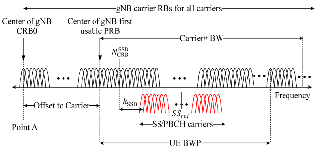
Almost same meaning as the digram shown above, I found another nice illustration explaining on this from On the Design Details of SS/PBCH, Signal Generation and PRACH in 5G-NR.
Maybe following figure (Figure 3) from the same paper look simpler (hopefully).
- Following table shows the time domain (OFDM symbol number) and frequency domain (Subcarrier Number) within SS/PBCH bloc.
< 38.211- Table 7.4.3.1-1: Resources within an SS/PBCH block for PSS, SSS, PBCH, and DM-RS for PBCH >
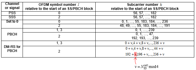
This table can be represented in Resource Grid as shown below. Note that the position of PBCH DM-RS varies with v and the value v changes depending on Physical Cell ID.
< Time Domain Resource Allocation >
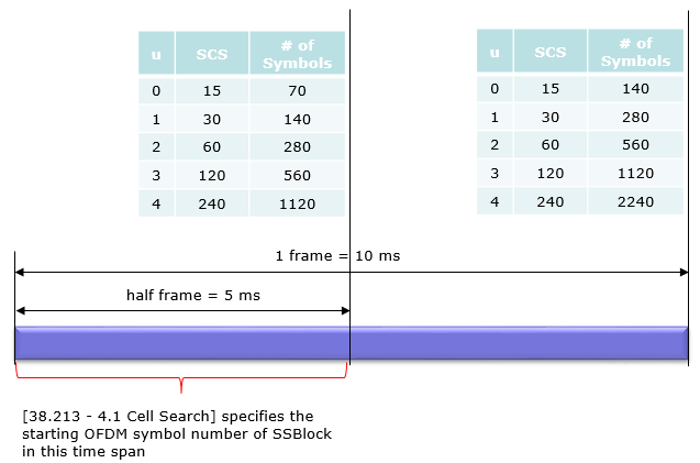
Following table indicates the first OFDM symbol number (s) where SS/PBCH is transmitted. This is based on 38.213 - 4.1 Cell Search.
The document states as follows :
For a half frame with SS/PBCH blocks, the number and first symbol indexes for candidate SS/PBCH blocks are determined according to the subcarrier spacing of SS/PBCH blocks as follows.
This mean that [38.213 - 4.1 Cell Search] specifies SS/PBCH location in time domain as illustrated below.
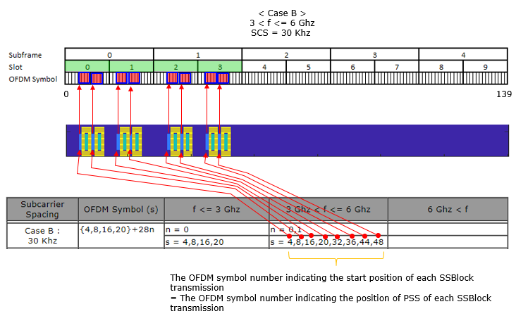
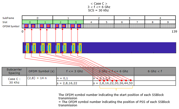
< Start Symbols for each subcarrier spacing and frequency >
NOTE : Case C definition has been changed a few times as 3GPP evolves, the current definition is based on 38.213 v17.2
NOTE : Lmax determines the bitlength of ssb bitmap
|
Subcarrier Spacing |
OFDM Symbol (s) |
f <= 3 Ghz |
3 Ghz < f <= 6 Ghz |
6 Ghz < f |
|
Case A : 15 KHz |
{2,8} + 14 n |
n = 0,1 |
n = 0,1,2,3 |
|
|
s = 2,8,16,22 (Lmax = 4) |
s = 2,8,16,22,30,36,44,50 (Lmax = 8) |
|
||
|
Case B : 30 Khz |
{4,8,16,20}+28n |
n = 0 |
n = 0,1 |
|
|
s = 4,8,16,20 (Lmax = 4) |
s = 4,8,16,20,32,36,44,48 (Lmax = 8) |
|
||
|
Case C : 30 Khz |
{2,8} + 14 n |
(TDD f < 3) n = 0,1 |
n = 0,1,2,3 (FDD) |
|
|
s = 2,8,16,22 (Lmax = 4) |
s = 2,8,16,22,30,36,44,50 (Lmax = 8) |
|
||
|
(TDD f < 1.88) n = 0,1 |
n = 0,1,2,3 (TDD) |
|
||
|
s = 2,8,16,22 (Lmax = 4) |
s = 2,8,16,22,30,36,44,50 (Lmax = 8) |
|
||
|
(TDD 1.88 < f < 3.0 ) n = 0,1,2,3 |
n = 0,1,2,3 (TDD) |
|
||
|
s=2,8,16,22,30,36,44,50 (Lmax = 8) |
s = 2,8,16,22,30,36,44,50 (Lmax = 8) |
|
||
|
Case D : 120 Khz |
{4,8,16,20} + 28n |
|
|
n=0, 1, 2, 3, 5, 6, 7, 8, 10, 11, 12, 13, 15, 16, 17, 18 |
|
|
|
s = 4,8,16,20, 32,36,44,48, 60,64,72,76, 88,92,100,104, 144,148,156,160, 172,176,184,188, 200,204,212,216, 228,232,240,244, 284,288,296,300, 312,316,324,328, 340,344,352,356, 368,372,380,384, 424,428,436,440, 452,456,464,468, 480,484,492,496, 508,512,520,524 (Lmax = 64) |
||
|
Case E : 240 Khz |
{8, 12, 16, 20, 32, 36, 40, 44} + 56n |
|
|
n=0, 1, 2, 3, 5, 6, 7, 8 |
|
|
|
s = 8,12,16,20, 32,36,40,44, 64,68,72,76, 88,92,96,100, 120,124,128,132, 144,148,152,156, 176,180,184,188, 200,204,208,212, 288,292,296,300, 312,316,320,324, 344,348,352,356, 368,372,376,380, 400,404,408,412, 424,428,432,436, 456,460,464,468, 480,484,488,492 (Lmax = 64) |
||
|
Case F : 480 Khz |
{2, 9} + 14n |
|
|
n=0, 1, 2, 3, 4, 5, 6, 7, 8, 9, 10, 11, 12, 13, 14, 15, 16, 17, 18, 19, 20, 21, 22, 23, 24, 25, 26, 27, 28, 29, 30, 31. |
|
|
|
s = 2,16,30,44, 58,72,86,100, 114,128,142,156, 170,184,198,212, 226,240,254,268, 282,296,310,324, 338,352,366,380, 394,408,422,436, 9,23,37,51, 65,79,93,107, 121,135,149,163, 177,191,205,219, 233,247,261,275, 289,303,317,331, 345,359,373,387, 401,415,429,443 (Lmax = 64) |
||
|
Case G : 960 Khz |
{2, 9} + 14n |
|
|
n=0, 1, 2, 3, 4, 5, 6, 7, 8, 9, 10, 11, 12, 13, 14, 15, 16, 17, 18, 19, 20, 21, 22, 23, 24, 25, 26, 27, 28, 29, 30, 31. |
|
|
|
s = 2,16,30,44, 58,72,86,100, 114,128,142,156, 170,184,198,212, 226,240,254,268, 282,296,310,324, 338,352,366,380, 394,408,422,436, 9,23,37,51, 65,79,93,107, 121,135,149,163, 177,191,205,219, 233,247,261,275, 289,303,317,331, 345,359,373,387, 401,415,429,443 (Lmax = 64) |
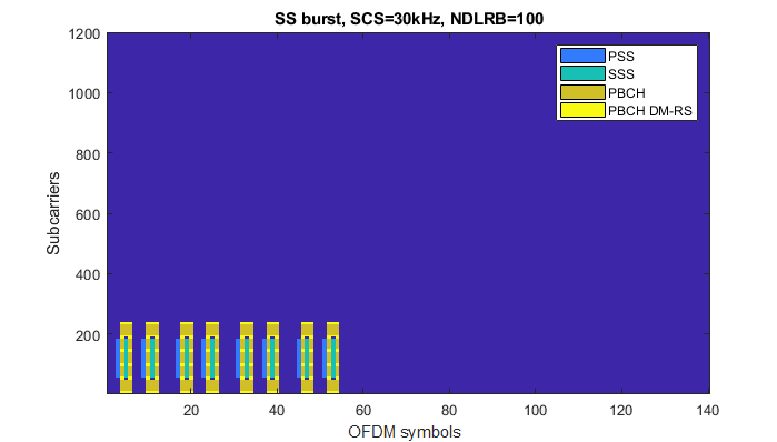
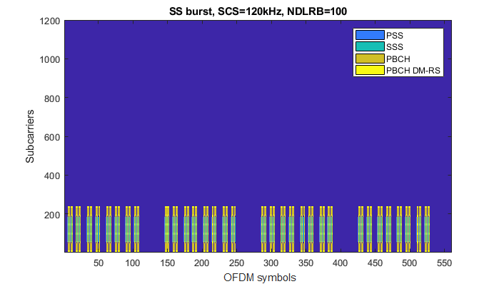
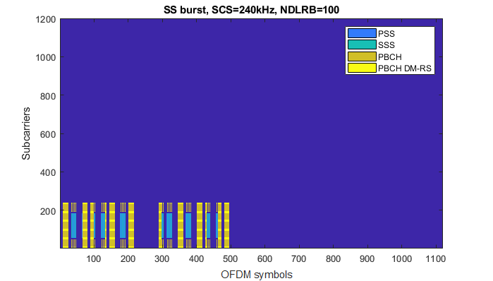
Followings are examples of SSB Transmission for each cases. For the simplicity, I set the frequency domain location of SSB block to be located at the bottom of the system bandwidth, but in reality the frequency domain location can change to other location (e.g, center frequency of the system bandwidth). The main purpose of these examples is o show the time domain location (transmission pattern) of each cases. In real deployment, it is highly likely (but not necessarily) that the frequency domain location of the SSB located around the center frequency.
The example below shows how you can correlate the above table to the SSB transmission plot shown in the following examples.
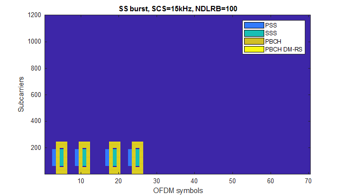
< Case A : f <= 3 Ghz >
This plot is created by Matlab 5G library. See this page for the Matlab code and more examples.
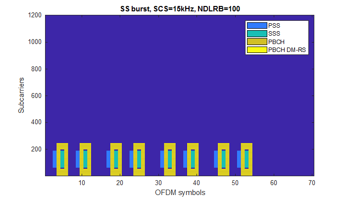
< Case A : 3 Ghz < f <= 6 Ghz >
This plot is created by Matlab 5G library. See this page for the Matlab code and more examples.
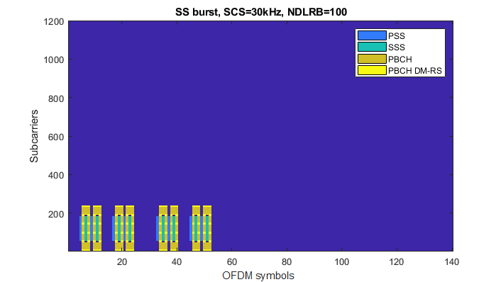
< Case B : f <= 3 Ghz >
This plot is created by Matlab 5G library. See this page for the Matlab code and more examples.

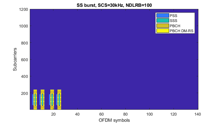
< Case B : 3 Ghz < f <= 6 Ghz >
This plot is created by Matlab 5G library. See this page for the Matlab code and more examples.
< Case C : f <= 3 Ghz >
This plot is created by Matlab 5G library. See this page for the Matlab code and more examples.
< Case C : 3 Ghz < f <= 6 Ghz >
This plot is created by Matlab 5G library. See this page for the Matlab code and more examples.
< Case D : 6 Ghz < f >
This plot is created by Matlab 5G library. See this page for the Matlab code and more examples.
< Case E : 6 Ghz < f >
This plot is created by Matlab 5G library. See this page for the Matlab code and more examples.
Reference
[1] 3GPP TSG RAN WG1 Meeting NR#3 : R1- 1716650 Comparison of PBCH DMRS mapping schemes
[2] 3GPP TSG RAN WG1 Meeting NR#3 : R1-1715841 Remaining Details on PBCH design and contents
[3] 3GPP TSG RAN WG1 Meeting AH_NR#3 : R1-1716609 - On remaining details of NR DL DMRS
[4] 3GPP TSG RAN WG1 NR Ad-Hoc#3 : R1-1716574 - Discussion on time domain resource allocation
[5] 5G NEW RADIO : Designing For The Future (Ericsson Technology Review)
[6] Making 5G NR a reality (Qualcomm)
[7] On the Design Details of SS/PBCH, Signal Generation and PRACH in 5G-NR
|
|
|