NOTE : At high level view, it would not be difficult to understand overall concept of CSI. However, getting deeper into the details.. it would become much complicated .. and tooooooooooooo confusing (at least very confusing to me). That is one of the reason why I wrote multiple pages for the same topic (CSI). Multiple pages for the same topic can be additional confusion to some readers (even to me). However, I thought the page would get too big for download if I put everything in single page and I also thought it would not be bad to provide a little bit different aspect for the same topic with multiple post. But as I add more pages (post), I thought it would be good to write a page to provide high level view and help readers combine all those multiple pages that I wrote. Refer to CSI Overview page if you are not familiar with big picture of the CSI report.
This page takes the periodic side of that pair. Answering it needs two numbers and one condition, and the two numbers are not carried in the message directly. Each one is an index that a table in 36.213 turns into a period and an offset.
When (on which subframe, with what interval) the CQI is transmitted ? There are two types of CQI transmission : Periodic and Aperiodic.
- Periodic CQI : CQI is transmitted periodically with a certain interval specified by higher layer message(e.g, RRC Connection Reconfiguration, RRC Connection Setup).
- Aperiodic CQI : CQI is transmitted by a special trigger (e.g, DCI0, RACH Response).
I will cover on following topics on this page.
- Configuration for Periodicity
- Wideband vs Subband
- PUCCH Reporting Type and Payload
- Influence of other MAC activities on CSI report
- Example 1 : Live Network Example - CQI, RI, PMI
- Reference
Configuration for Periodicity
Let's look into Periodic Report first. As mentioned above, in Periodic report configuration CQI/PMI/RI is transmitted periodically with a certain interval specified by higher layer message(e.g, RRC Connection Reconfiguration, RRC Connection Setup)
Following RRC configuration (RRC Connection Setup or RRC Connection Reconfiguration) notifies UE of CQI, PMI, RI reporting configuration. (cqi-PUCCH-ResourceIndex is "Resource index for PUCCH formats 2/2a/2b")
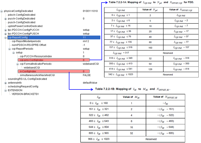
Two fields of the message and two tables of the specification. The arrows are the whole of the mapping.
Only two fields decide the timing : cqi-pmi-ConfigIndex and ri-ConfigIndex, both highlighted in the tree and both zero in this capture.Each index goes to its own table : Table 7.2.2-1A for the CQI index and Table 7.2.2-1B for the RI index.Each table returns two values, not one : a period and an offset. The offset column is a formula rather than a number.The FDD period rises in a familiar run : 2, 5, 10, 20, 40, 80 and 160 subframes.Then it stops being monotonic : indices 318 to 541 give 32, 64 and 128. Those rows sit after the 160 row rather than before it.Two ranges of the index are reserved : the single value 317, and everything from 542 to 1023.The RI table has no periods at all : its middle column holds MRI, which is 1, 2, 4, 8, 16 or 32.Its six bands are all the same width : 161 indices each, from 0 to 965, with 966 to 1023 reserved.
But just from RRC message and the two tables (from 36.213), you cannot know exactly at which subframe the CQI/PMI/RI are transmitted. To figure out the exact time stamp (SFN and subframe) you have to go through several mathematical equations as follows. These two equations are only part of the story. For the full story, you have to refer to 36.213 7.2.2 Periodic CSI Reporting using PUCCH. You will see the many different cases of reporting cycle. I just use this two example to show you how to interpret these equation.
CQI Periodicity
Following is an example when CQI only is being transmitted. Npd and N_OFFSET,CQI configured by RRC Connection Setup and RRC Connection Reconfiguration and the value itself came from Table 7.2.2-1A of 36.213.
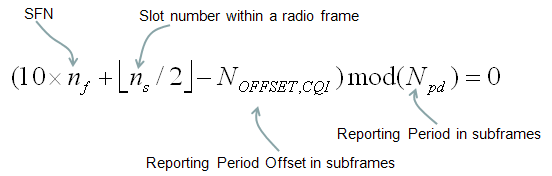
Four terms, and the two on the left only convert a frame and slot count into a subframe count.
The first two terms are a clock, not a parameter : 10 times nf turns the system frame number into subframes. The floor of ns over 2 turns the slot number into a subframe inside that frame.Ten and two are the frame structure : ten subframes in a radio frame and two slots in a subframe.NOFFSET,CQI slides the whole pattern : it is subtracted before the modulo, so it moves which subframe the reports land on.Npd sets how often they land : the condition is satisfied once every Npd subframes and never in between.The result is a fixed grid : nothing in the condition depends on the channel. So the instants are known as soon as the RRC message is read.
The equation itself will be quite simple, but just to doublecheck your understanding, let me give you a short quizz (don't get panic -:)). Here you go.
Let's try with some example for a FDD case.
If cqi-pmi-Configindex in RRC message is 13. What is Npd and N_OFFSET,CQI ?
This maps to the row of the table as follows. You can read Npd directly. It is 10. Then you need a little bit of math to get N_OFFSET,CQI. The value for this example is specified to be (I_CQI/PMI-7). It is "13 -7" which is 6. Now the last step is to apply these two values to the equation above to calculate the exact subframe number for CQI/PMI transmission.
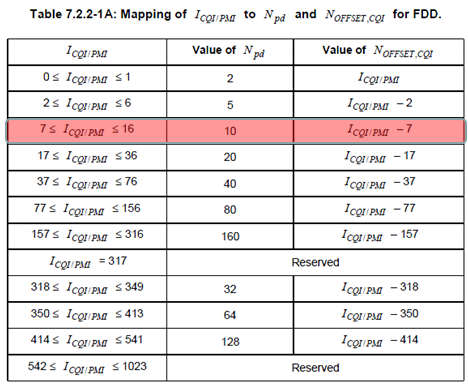
The highlighted row is the one the quiz above lands in. Reading Npd is a lookup, and the offset still needs the subtraction.
The highlighted band is 7 to 16 : index 13 falls inside it, so Npd is 10.The offset is the index less the band start : 13 minus 7 is 6, so NOFFSET,CQI is 6.Every band works the same way : the offset column subtracts the first index of the band. The offset therefore always starts at zero.The band width is the period : the 7 to 16 band holds ten indices and gives a period of 10. That is what lets the offset cover every subframe of the cycle.Index 13 therefore reports in subframe 6 of every radio frame : the condition needs the subframe count less 6 to be a multiple of 10.
Note : I_CQI/PMI is specified by physicalConfigDedicated.cqi-ReportConfig.cqi-ReportPeriodic.setup.cqi-pmi-ConfigIndex in a RRC Message (e.g, RRC Connection Reconfiguration)
If it is for TDD case, we use the following table in 36.213. The way you interpret the table is same as in FDD.
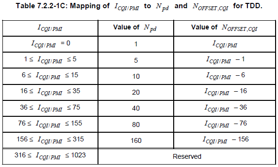
The same job for TDD, and it is not the same table. Compare the top row and the bottom row against the FDD one.
TDD adds a period of 1 and drops the period of 2 : index 0 alone gives Npd equal to 1. The FDD table starts at 2.TDD has no 32, 64 or 128 rows : those three FDD periods have no TDD counterpart in this table.So the TDD index space is much smaller : everything from 316 upward is reserved, against 542 in the FDD table.The band boundaries move by one : 6 to 15 gives a period of 10 in TDD where 7 to 16 does in FDD. The extra period of 1 shifted everything down.The three notes below are the reason for the difference : the shortest periods need uplink subframes to land on. Only some uplink and downlink configurations provide enough of them.
There are several things you need to be careful about TDD since UE cannot transmit the report in any subframe. So you would have different restrictions depending on subframe configration. According to 36.213 7.2.2, there are following contraints for TDD.
- The reporting period of N_pd = 1 is only applicable to TDD UL/DL configurations 0, 1, 3, 4, and 6, where all UL subframes in a radio frame are used for CQI/PMI reporting.
- The reporting period of N_pd = 5 is only applicable to TDD UL/DL configurations 0, 1, 2, and 6.
- The reporting periods of N_pd = {10,20,40,80,160} are applicable to all TDD UL/DL configurations.
RI Periodicity
Adding RI to a periodic report changes the condition rather than replacing it. The modulus grows, and a second offset joins the first. So the RI instants are a subset of a longer cycle built on the CQI one.
Following is an example where both CQI and RI are being transmitted.
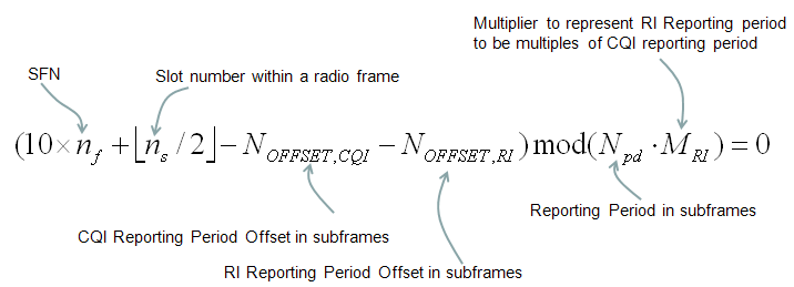
The CQI condition with two changes. Both of them are on the right hand side of the minus signs.
The modulus is now a product : Npd times MRI. So the RI period is always a whole multiple of the CQI period.The red note on the drawing says exactly that : it calls MRI a multiplier. The RI reporting period is a multiple of the CQI reporting period.Both offsets are subtracted : NOFFSET,CQI and NOFFSET,RI together decide where in the cycle the RI lands.NOFFSET,RI is never positive : every entry in Table 7.2.2-1B is zero or negative. So subtracting it shifts the instant later rather than earlier.An RI offset of zero puts RI on a CQI instant : the modulus is a multiple of Npd. So with nothing to displace it the two conditions are satisfied together.
just to doublecheck your understanding, let me give you a short quizz. Here you go.
If ri-Configindex in RRC message is 200. What is M_RI and N_OFFSET,RI ?
This maps to the row of the table as follows. You can read M_RI directly. It is 2. Then you need a little bit of math to get N_OFFSET,RI. The value for this example is specified to be -(I_RI-161). It is -(200-161) which is -39. Now the last step is to apply these two values to the equation above to calculate the exact subframe number for RI transmission.
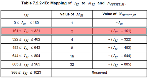
Six bands of equal width, and the multiplier doubles at every boundary.
The highlighted band is 161 to 321 : index 200 falls inside it, so MRI is 2.The offset is the negated distance into the band : minus 200 less 161 is minus 39.The multipliers are powers of two : 1, 2, 4, 8, 16 and 32, one per band.Every band is 161 indices wide : 0 to 160, then 161 to 321, and so on to 805 to 965.161 is also the largest displacement : the offset runs from 0 to minus 160 inside a band. That is why the band is that wide.The last 58 indices do nothing : 966 to 1023 are reserved.
Note : I_RI is specified by physicalConfigDedicated.cqi-ReportConfig.cqi-ReportPeriodic.setup.ri-ConfigIndex in a RRC Message (e.g, RRC Connection Reconfiguration)
Wideband vs Subband
One field decides whether a report describes the whole carrier or a slice of it. That choice changes the payload as well as the meaning. The drawing below puts the two next to each other, with the configuration that selects them on the left.
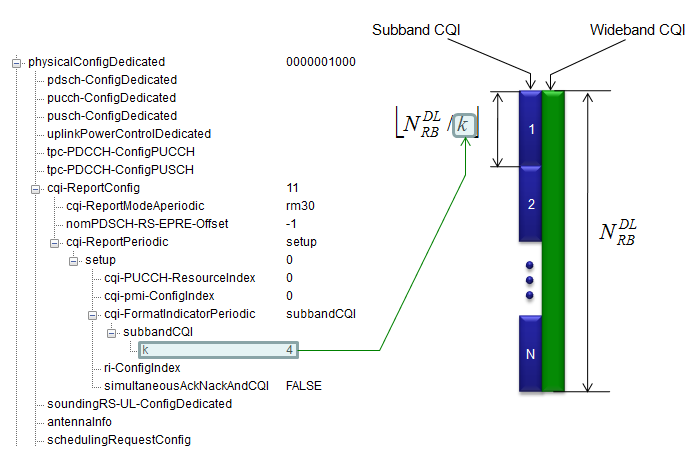
Green is one number for the whole carrier. Blue is the same carrier cut into N pieces, and one field decides how wide a piece is.
The choice is made by cqi-FormatIndicatorPeriodic : the tree shows it expanded to subbandCQI, with k underneath it.k is boxed at 4 in this capture : 36.331 gives it as INTEGER 1 to 4. So this is the top of its range.k is the width of a subband in resource blocks : the drawing puts the subband count at the ceiling of NRBDL over k.The green bar is one block from top to bottom : a wideband report is one value covering the same NRBDL.The blue bar is numbered 1 to N : each segment is a subband. A periodic report describes one of them at a time.Only one number is sent either way : a subband report is not N values at once. That is why the reporting cycle matters as much as the format.
Wideband trades detail for speed : one value describes the whole carrier and the next report is due in Npd subframes.Subband trades speed for detail : each report covers a slice, so the whole carrier takes several cycles to describe.k is the only setting to turn : a smaller k gives more subbands and a longer sweep. A larger k gives the opposite.The format appears again in the payload table below : the subband reporting types carry a field the wideband ones do not.
PUCCH Reporting Type and Payload
A periodic report has to fit in PUCCH, so its size is fixed in advance rather than decided per report. The table below is where that size is settled, and it is indexed by three things at once.
From 36.213
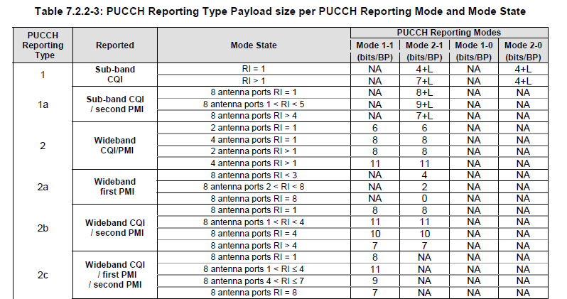
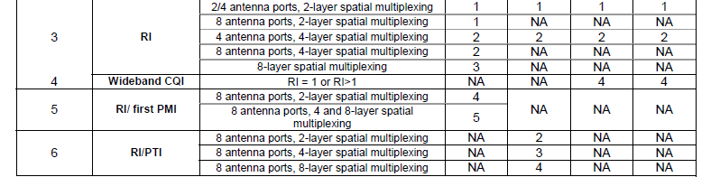
The rank reports and the no PMI reports. Two rows here are the only ones that appear in all four modes.
The size depends on three things : the reporting type, the mode state, and which of the four reporting modes is in force.The four modes split into two families : Mode 1-1 and Mode 2-1 carry PMI. Mode 1-0 and Mode 2-0 do not.Only the subband types carry a plus L : types 1 and 1a print 4+L, 7+L, 8+L and 9+L. Every wideband type prints a plain number.L is the subband label : the note under the table sends you to 36.213 clause 7.2.2 for its definition. It is the cost of saying which subband the value describes.Type 2a with eight layers costs nothing : its row for RI equal to 8 prints 0 bits. That is a reporting instance that carries no payload.More layers does not mean more bits : type 2b runs 8, 11, 10 and 7 bits as the rank climbs. So the largest payload is in the middle.
Type 3 carries RI and appears in every mode : its 2 and 4 antenna port rows print one value across all four columns.The RI payload is the log of the layer count : 1 bit for two layers, 2 for four and 3 for eight.Type 4 is the only one the no PMI modes use : it prints 4 bits under Mode 1-0 and Mode 2-0. Both PMI modes print NA.So a no PMI configuration sends two things : a wideband CQI as type 4 and a rank as type 3. Nothing else is sent.Types 5 and 6 exist only for eight antenna ports : every one of their mode states names eight antenna ports.Type 6 carries a PTI alongside the rank : 2, 3 or 4 bits in Mode 2-1, by layer count.
Nothing here exceeds eleven bits : the whole table runs from 0 to 11 bits plus L. That is what a PUCCH report has room for.The mode is chosen once and fixes the whole column : it decides which types are ever sent. Size is the smaller half of that.A reporting instance sends one type, not a set : the cycle worked out above decides which type falls where.Ten types is the price of fitting CSI into PUCCH : the report is broken into pieces small enough to send. The pieces are then spread over time.
Note : For the definition of 'L', refer to 36.213 7.2.2 Periodic CSI Reporting using PUCCH
Influence of other MAC activities on CSI report
Since there are some other periodic activities, those activities can influence Periodic/Aperidic CSI Report as described in CQI Report and DRX section. CSI report is triggered by DCI, so a certain DCI format can influence CSI Report as described in CQI Report and SR section.
Two of those activities are worth naming, because both have a clause that settles the collision outright. Neither of them moves the report to a later instant.
A positive scheduling request drops the CSI : 36.213 clause 7.2.2 gives the request priority when both want one subframe.Connected mode DRX suppresses it while the UE sleeps : 36.321 clause 5.7 stops the report outside the active time, and the cqi-Mask setting narrows that window further.The grid does not shift to compensate : the condition worked out above is a function of the frame number. A missed instant is simply missed.That makes a configured period an upper bound : the formula predicts a set, and the reports that arrive are a subset of it.A quiet stretch in a log is worth checking twice : it may be the channel. It may be a DRX cycle or a run of scheduling requests.
The aperiodic half of that first sentence works in the opposite direction. Nothing suppresses an aperiodic report, because nothing schedules one in advance.
An aperiodic report is asked for, not timed : no formula on this page applies to it. No index in the RRC message sets its cadence.So the collisions above cannot arise : the grant that requests the report also allocates the PUSCH it travels on.The two mechanisms fail differently : a periodic report goes missing silently. An aperiodic one only goes missing if the grant itself did.That is the practical reason to configure both : the periodic grid keeps a baseline running. An aperiodic request fills the gaps when the network needs a fresh answer.
Example 1 : Live Network Example - CQI, RI, PMI
Following is an example configuration from a live network captured by a drive test tool from Azenqos. The tool has capability of RRC / NAS message capturing and decoding capability.
RRCConnectionSetup decoded from a live network capture, quoted as the author recorded it. The rows of dots are the author's cut, so the braces do not balance and have been left that way. None of its values have been corrected against a specification.
DL-CCCH-Message ::= {
    message: c1: rrcConnectionSetup: RRCConnectionSetup ::= {
        rrc-TransactionIdentifier: 1
        criticalExtensions: c1: rrcConnectionSetup-r8: RRCConnectionSetup-r8-IEs ::= {
            radioResourceConfigDedicated: RadioResourceConfigDedicated ::= {
                .....
                }
                mac-MainConfig: explicitValue: MAC-MainConfig ::= {
                ....
                }
                physicalConfigDedicated: PhysicalConfigDedicated ::= {
                    pdsch-ConfigDedicated: PDSCH-ConfigDedicated ::= {
                        ...
                    }
                    pucch-ConfigDedicated: PUCCH-ConfigDedicated ::= {
                        ...
                    }
                    pusch-ConfigDedicated: PUSCH-ConfigDedicated ::= {
                        ...
                    }
                    uplinkPowerControlDedicated: UplinkPowerControlDedicated ::= {
                        ...
                    }
                    tpc-PDCCH-ConfigPUCCH: release: <present>
                    tpc-PDCCH-ConfigPUSCH: release: <present>
                    cqi-ReportConfig: CQI-ReportConfig ::= {
                        cqi-ReportModeAperiodic: 4 (rm31)
                        nomPDSCH-RS-EPRE-Offset: 0
                        cqi-ReportPeriodic: setup: setup ::= {
                            cqi-PUCCH-ResourceIndex: 2
                            cqi-pmi-ConfigIndex: 2
                            cqi-FormatIndicatorPeriodic: widebandCQI: <present>
                            ri-ConfigIndex: 644
                            simultaneousAckNackAndCQI: FALSE
                        }
                    }
                    soundingRS-UL-ConfigDedicated: release: <present>
                    antennaInfo: explicitValue: AntennaInfoDedicated ::= {
                        transmissionMode: 3 (tm4)
                        codebookSubsetRestriction: n4TxAntenna-tm4: FF FF FF FF FF FF FF FF
                        ue-TransmitAntennaSelection: release: <present>
                    }
                    schedulingRequestConfig: setup: setup ::= {
                        ...
                    }
                }
            }
        }
    }
}
The red marking is the author's : it picks out cqi-ReportConfig and the seven lines inside it.The field order matches 36.331 : cqi-ReportModeAperiodic, nomPDSCH-RS-EPRE-Offset and cqi-ReportPeriodic, then the five fields of setup.4 is rm31 : 36.331 enumerates the aperiodic modes as rm12, rm20, rm22, rm30 and rm31. The decoder prints both the index and the name.The format is wideband : cqi-FormatIndicatorPeriodic reads widebandCQI, so no k appears and the subband branch is unused.The transmission mode is tm4 : closed loop spatial multiplexing, which is why a rank indication is configured at all.Everything outside cqi-ReportConfig is cut : pdsch, pucch, pusch and the power control blocks all show a row of dots.
The two indices in that capture are worth carrying through the tables above. They give the reporting grid for this connection exactly.
cqi-pmi-ConfigIndex is 2 : Table 7.2.2-1A puts that in the band 2 to 6. So Npd is 5 and NOFFSET,CQI is 2 less 2, which is 0.So CQI is reported twice per radio frame : the condition reduces to the subframe count being a multiple of 5. That is subframe 0 and subframe 5.ri-ConfigIndex is 644 : Table 7.2.2-1B puts that at the very start of the band 644 to 804. So MRI is 16 and NOFFSET,RI is 0.So RI is reported once every eight radio frames : the modulus is 5 times 16, which is 80 subframes.Both offsets came out zero : each index sits at the first value of its band. So the RI instant coincides with a CQI instant.Sixteen CQI reports arrive for every rank report : that ratio is what the plot below shows without any arithmetic.
Following is the result of CQI / PMI / RI from UE. This data is also from Azenqos tool, and I exported the data into csv file and process in Microsoft Excel. Since the timing of the report is not expressed as SFN : Subframe, it is hard to validate the exact report timing and cycle. But I wanted to show how dynamically live network situation changes and UE needs to cope with such dynamic radio link environment. (You may be pretty familiar with CQI, but might be familiar with RI and PMI, especially have hard time interpreting the value of PMI index. Refer to Rank Index page for RI and LTE PHY Processing Page and Precoding page for PMI)
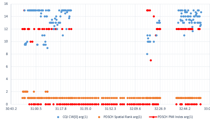
Three quantities on one axis, moving at three different rates. The slowest one is the one the configuration made slowest.
The blue series is the reported CQI : it scatters between about 8 and 15. The value changes from one sample to the next.The orange series is the PDSCH spatial rank : it sits at 1 almost throughout. A handful of samples early on reach 2.The red series is the PDSCH PMI index : it holds 12 for long stretches. Brief excursions reach 10, 14, 15 and 7.The rank moves far less often than the CQI : the indices in the capture set that ratio at 16 to 1.Rank 1 under tm4 is the common case : the mode allows two layers. The channel gave one for nearly the whole run.The two lower series are what the network used : the legend says PDSCH rank and PDSCH PMI. So they record the transmission rather than the report.
Reference
The two documents below are the ones this page works from. Every table reproduced here is a screenshot of the first. The field names and ranges were checked against the second in the version named.
- 36.213 : 3GPP - E-UTRA; Physical layer procedures. Clause 7.2.2 is Periodic CSI Reporting using PUCCH. It holds Table 7.2.2-1A for FDD, Table 7.2.2-1B for the rank index, Table 7.2.2-1C for TDD and Table 7.2.2-3 for the reporting type payloads.
- 36.331 : 3GPP - E-UTRA; Radio Resource Control (RRC); Protocol specification, v19.3.0. The source of CQI-ReportConfig, CQI-ReportPeriodic and CQI-ReportModeAperiodic, which the capture in the last section decodes against.