|
5G CSI Report in Detail
At high level, the concept of CSI Report (Channel State Information) in NR is similar to CSI Report in LTE, but the details especially on the resource application of various reference signal and scheduing of the report is extremely complex than LTE. In this page, I will describe on high level view on CSI report mechanism and I would need to create many separate pages to describe the details like sequence generation and resource element mapping of those referenec signals.
- Building Up Intuition
- Component of CSI and Hierarchies in CSI Framework
- Which signal to use for CSI report ?
- Higher Layer Framework of CSI Report
- How to configure Report Setting /Structure of CSI-ReportConfig
- Reporting Parameters and dependencies
- ReportConfig Details
- carrier
- CodebookConfig
- cqi-FormatIndicator
- cqi-Table
- csi-IM-ResourcesForInterference
- csi-ReportingBand
- groupBasedBeamReporting
- non-PMI-PortIndication
- nrofReportedRS
- nzp-CSI-RS-ResourcesForInterference
- p0alpha
- pmi-FormatIndicator
- PortIndexFor8Ranks
- reportQuantity
- timeRestrictionForChannelMeasurements
- timeRestrictionForInterferenceMeasurements
- Reporting Granularity - Subband vs Wideband
- Trigger Mapping between Resource Configuration and Report Configuration
- CSI Report Sequence Flow : Periodic vs Aperiodic
- How long does it take for UE to compute CSI measurement result ?
- How to configure Aperiodic Report Trigger ?
- RRC Parameters for CSI Report
- RRC Examples
- Basic Template
- CSI RS for Tracking
- NZP-CSI-RS for Tracking
- NZP CSI-RS for CSI Acquisition
- ZP CSI-RS for CSI Acquisition
- PDSCH-Config [TCI States]
- CSI-RS for beam refinement
- CSI-RS for beam management
- Get the Test Procedure and Log / Amarisoft TechAcademy
Building up Intuition
Before we jump into the details of CSI measurement process, I want to share a snapshot of intuition about this process. This is my intuition of the entire beam management procedure based on CSI report and what I am trying to do in this note is to provide you with the full details behind this intuition. For the descriptions and slideshow of this animation, check out this.
Component of CSI and Hierarchies in CSI Framework
As in LTE, there are several components of CSI in NR(i.e, severl different types of CSI). The difference is that the number of the comonents are larger and operating mechanism is much complicated than in LTE. Followings are the components on CSI in NR (Based on 38.214 - 5.2.1) .
- CQI(Channel Qulity Information)
- PMI(Precoding Matrix Indicator)
- CRI(CSI-RS Resource Indicator)
- SSBRI(SS/PBCH Resource Block Indicator)
- LI(Layer Indicator)
- RI(Rank Indicator) an/or L1-RSRP
Higher Layer Framework of CSI Report
CSI Report framework is made up of two large parts. One is for the configuration and the other one is for Triggering States which are associated a specific configuration as illustrated below (based on 38.214 - 5.2.1).
Following is overall description on the framework and the relationships among each components.
XXX-YYY-Resource : This parameter defines the physical location (i.e, the location of physical resource element) of the various CSI related reference signal. There are three types of the resources belonging to this catetory. They are NZP-CSI-RS resource, ZP-CSI-RS resource, IM Resource. The way to define the specific locations of these resource is quite complicated and confusing, so I wrote a separate note only to explain how to define those resource locations. The Rrc message information element for these resources are listed below.- PDSCH-Config
- zp-CSI-RS-ResourceToAddModList -> ZP-CSI-RS-Resource -> CSI-RS-ResourceMapping
- CSI-MeasConfig
- nzp-CSI-RS-ResourceToAddModList -> NZP-CSI-RS-Resource -> CSI-RS-ResourceMapping
- csi-IM-ResourceToAddModList -> CSI-IM-Resource
ResourceSet : XXX-YYY Resource defines individual resources. But in NR all the individual resources should belong to a specific group to be really used. Even if only one resource are to be used, it should belong to a group. That group is called as a ResourceSet. The ResourceSet is configured in the following RRC.- nzp-CSI-RS-ResourceSetToAddModList->NZP-CSI-RS-ResourceSet->nzp-CSI-RS-Resources
- csi-SSB-ResourceSetToAddModList -> CSI-SSB-ResourceSet -> SSB-Index
CSI ResourceConfig specifies on what type of reference signal(nzp-CSI-RS-SSB, csi-IM-Resource) is to be transmitted. It also configures the types of the transmission (periodic, aperiodic, semipersistent). XXX-YYY-Resource and ResourceSet just defines the structure of the CSI resources. They don't trigger the transmission of the resources. It is CSI ResourceConfig that triggers the transmission of the resources.CSI ReportConfig specifies which of CSI ResourceConfig to be used for the measurement. It has the mapping table between the measurement type and the corresponding CSR ResourceConfig ID.
The description mentioned above can be illustrated as below. If this diagram does not make clear sense to you, take a look at another diagram after this and see if it make more sense.

Here goes the another diagram showing the structure (relashionship) of all of these components.
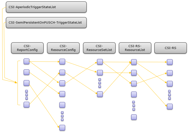
Note : Just for the quick reference, I put the link of ASN message of each components in the illustration above.
The RRC Structure for CSI Report is the most complicated one in NR and I don't have any efficient way to get all of you to understand just by writing this kind of note. Understanding this structure would require some efforts from each of you. What I can give you is just some guidelines or tips to help you get some big picture.
Which signal to use for CSI report ?
There are two types of signal you can use for CSI report. One is SSB and the other one is CSI-RS and each of them has its own advantage and disadvantage.
How to configure Report Setting /Structure of CSI-ReportConfig
How to configure CSI Report setting ? The simple answer is 'Look at CSI-ReportConfig', but it is too many parameters and too complicated. So in this section, I will try to give you some big picture of the structure of this configuration based on 38.214-5.2.1.1.
The overall structure of CSI-ReportConfig can be summarized as follows.
reportConfigType : this parameter indicates the scheduling method of the report. It can be periodic, aperiodic and semiPersistent as listed below.- aperiodic
- semiPersistentOnPUCCH
- semiPersistentOnPUSCH
- periodic
reportQuantity : this parameter indicates what to measure. The type of quatities can be grouped into two types as listed below.- CSI-related quantities
- L1-RSRP-related quantities
reportFreqConfiguration : this indicates the reporting granularity in frequency domain. It can be wideband or subband.timeRestrictionForChannelMeasurements : It indicates whether to put the restriction on channel measurement in time domain or not.timeRestrictionForInterferenceMeasurements : It indicates whether to put the restriction on interferencel measurement in time domain or not.codebookConfig : It configures the parameters for type 1 and type 2.- Type I
- Type II
Reporting Parameters and dependencies
Each of Reporting Parameters are calculated from one or more other parameters(dependencies) as listed below (38.214-5.2.1.4)
|
Reporting Parameters |
Dependencies |
|
LI |
CQI,PMI,CRI,RI |
|
CQI |
PMI,RI,CRI |
|
PMI |
RI,CRI |
|
RI |
CRI |
Let me describe on this parameters in more detail in terms of RRC parameters based on 38.214-5.2.1.4.2. Since CSI Report configuration would be the most complicated / confusing setup in NR protocol, it would be most likely for you to make mistake in implementing or analyzing the signaling message for the configuration. So it will be very helpful to clearly understand the fundamental requirement and the dependency among various RRC configurations for each type of Report quantity.
|
ReportQuantity |
Description |
|
cri-RI-PMI-CQI cri-RI-LI-PMI-CQI ([1]) |
|
|
cri-RI-i1 |
|
|
cri-RI-i1-CQI |
|
|
cri-RI-CQI |
|
|
cri-RSRP ssb-index-RSRP |
|
|
cri-SINR ssb-index-SINR |
|
| Common to All |
|
Meaning of LI is described in 38.214-5.2.1.4.2 as follows.
The LI indicates which column of the precoder matrix of the reported PMI corresponds to the strongest layer of the codeword corresponding to the largest reported wideband CQI. If two wideband CQIs are reported and have equal value, the LI corresponds to strongest layer of the first codeword.
ReportConfig Details
I am trying to write down the details on parameters of CSI-ReportConfig collected from various source. The report quantity can be categorized roughly into two types : subband and wideband. Subband vs Wideband details are described in next section.

- enabled : UE shall report different CRI or SSBRI for each report setting in a single report nrofReportedRS
- disabled : UE shall report in a single reporting instance two different CRI or SSBRI for each report setting, where CSI-RS and/or SSB resources can be received simultaneously by the UE either with a single spatial domain receive filter, or with multiple simultaneous spatial domain receive filters.
- Group based reporting: The N downlink Tx beams in a reporting instance can be received simultaneously by the UE by multiple receive panels. This means that the subsequent DL transmission can be scheduled with up to N downlink Tx beams. For instance, the UE enables two antenna panels to simultaneously receive two independent Tx beams, which experience a line-of-sight (LOS) path and a strong non-line-of-sight (NLOS) path, respectively.
- Non group based reporting: UE reports the N downlink beams with the N-best received power without further UE assumption about simultaneous reception for these N beams. In the other word, the subsequent DL transmission can only be performed with only one Tx beam selected from the N beams since TRP does not know which beams can be simultaneously received by the UE.
The concept of group based beam management is to manage beams in group basis instead of beam-by-beam basis, considering that beams sharing similar channel properties can be put into the same beam group.
With group based reporting, a UE can help a TRP to identify multi-path observed by the UE and let the TRP know theUE beam information implicitly
- The first entry in non-PMI-PortIndication corresponds to the
list of port index to be used for Rank 1 measurement. The CSI-ResourceConfigId is indicated in a CSI-MeasId together with the above CSIReportConfigId; - The second entry in non-PMI-PortIndication corresponds to
list of port index to be used for Rank 2 measurement. - and so on.
The purpose of this IE is to let the UE to use which csi-rs to use for RI report when PMI report is not configured. This IE is used only when ReportQuantity is cri-RI-CQI. In this case, the codebook is not used and CSI-RS for the codebook configuration would not be used. So we need to specify other CSI-RS ports which should be used for RI measurement and report. For example, 4x4 MIMO case (rank 4 case) you have to sepcify following
- Use these port for rank 4 measurement
- Use these port for rank 3 measurement'
- Use these port for rank 2 measurement
- Use this port for rank 1 measurement
The structure of this IE is as follows
PortIndexFor8Ranks ::= CHOICE { // Check this for the meaning of this IE
portIndex8 SEQUENCE{
rank1-8 PortIndex8 OPTIONAL, -- Need R
rank2-8 SEQUENCE(SIZE(2)) OF PortIndex8 OPTIONAL, -- Need R
rank3-8 SEQUENCE(SIZE(3)) OF PortIndex8 OPTIONAL, -- Need R
rank4-8 SEQUENCE(SIZE(4)) OF PortIndex8 OPTIONAL, -- Need R
rank5-8 SEQUENCE(SIZE(5)) OF PortIndex8 OPTIONAL, -- Need R
rank6-8 SEQUENCE(SIZE(6)) OF PortIndex8 OPTIONAL, -- Need R
rank7-8 SEQUENCE(SIZE(7)) OF PortIndex8 OPTIONAL, -- Need R
rank8-8 SEQUENCE(SIZE(8)) OF PortIndex8 OPTIONAL -- Need R
},
portIndex4 SEQUENCE{
rank1-4 PortIndex4 OPTIONAL, -- Need R
rank2-4 SEQUENCE(SIZE(2)) OF PortIndex4 OPTIONAL, -- Need R
rank3-4 SEQUENCE(SIZE(3)) OF PortIndex4 OPTIONAL, -- Need R
rank4-4 SEQUENCE(SIZE(4)) OF PortIndex4 OPTIONAL -- Need R
},
portIndex2 SEQUENCE{
rank1-2 PortIndex2 OPTIONAL, -- Need R
rank2-2 SEQUENCE(SIZE(2)) OF PortIndex2 OPTIONAL -- Need R
},
portIndex1 NULL
}
- Configured : UE shall derive the channel measurements for computing CSI reported in uplink slot n based on only the most recent,no later than the CSI reference resource, occasion of NZP CSI-RS associated with the CSI resource setting.
- NotConfigure : the UE shall derive the channel measurements for computing CSI value reported in uplink slot n based on only the NZP CSI-RS, no later than the CSI reference resource, associated with the CSI resource setting.
- Configured : UE shall derive the interference measurements for computing the CSI value reported in uplink slot n based on the most recent, no later than the CSI reference resource, occasion of CSI-IM and/or NZP CSI-RS for interference measurement associated with the CSI resource setting.
- NotConfigure : the UE shall derive the interference measurements for computing CSI value reported in uplink slot n based on only the CSI-IM and/or NZP CSI-RS for interference measurement no later than the CSI reference resource associated with the CSI resource setting.
|
Value |
Description (based on 38.214 - 5.2.1.4) |
| Wideband |
a wideband CQI is reported for each codeword for the entire CSI reporting band |
| Subband |
one CQI for each codeword is reported for each subband in the CSI reporting band.. |
|
Value |
Description (based on 38.214 - 5.2.1.4) |
| Wideband |
a PMI is reported for the entire CSI reporting band |
| Subband |
Case 1 : Number of Antenna port is NOT 2 Single Wideband indicator for whole CSI band is reported via i1 and one subband indication for each subband is report via i2. Case 2 : Number of Antenna port is 2 a PMI is reported for each subband in the CSI reporting band. |
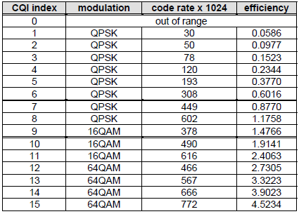
< 38.214 - Table 5.2.2.1-2: 4-bit CQI Table 1>

< 38.214 - Table 5.2.2.1-3: 4-bit CQI Table 2>
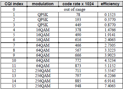
< 38.214 - Table 5.2.2.1-4: 4-bit CQI Table 3>
Reporting Granularity - Subband vs Wideband
There are roughly two options when it comes to reporting based on the following question : Does the report value represent the whole frequency ? or only some specific segment of the frequency ?
The report value (measured value) representing the whole frequency band is called 'Wideband' reporting and the value representing a specific segment of the band is called 'Subband' reporting. It can be summarized as follows as per 38.214 - 5.2.1.4
Wideband : UE report one CQI/PMI report per Codeword for the whole band.Subband : UE report one CQI/PMI report per Codeword for each subband whole band.
Wideband vs Subband is determined by one or combination of a few RRC parameters as summarized below (based on 38.214 - 5.2.1.4)
|
reportQuantity |
Frequency Granularity |
||
|
cri-RI-PMI-CQI or cri-RI-LI-PMI-CQI |
widebandCQI |
widebandPMI |
Wideband |
|
cri-RI-i1 |
Any |
Any |
Wideband |
|
cri-RI-CQI or cri-RI-i1-CQI |
widebandCQI |
Any |
Wideband |
|
cri-RSRP or ssb-Index-RSRP |
Any |
Any |
Wideband |
|
Else |
Subband |
||
When UE perform the report with subband granularity, it should know of the size and location of the subbands it need to measure. How these are determined ? It determined partially by predefined specification and partially by RRC configuration.
< 38.214-Table 5.2.1.4-2: Configurable subband sizes >
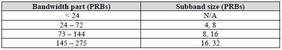
The number of PRBs indicated by each Bit in the suband IE is determined by the table shown above(38.214-Table 5.2.1.4-2). Basically the number of PRB for each bit varies with the bandwidth of the BWP.
reportFreqConfiguration SEQUENCE {
cqi-FormatIndicator ENUMERATED { widebandCQI, subbandCQI } OPTIONAL,
pmi-FormatIndicator ENUMERATED { widebandPMI, subbandPMI } OPTIONAL,
csi-ReportingBand CHOICE {
subbands3 BIT STRING(SIZE(3)),
subbands4 BIT STRING(SIZE(4)),
subbands5 BIT STRING(SIZE(5)),
subbands6 BIT STRING(SIZE(6)),
subbands7 BIT STRING(SIZE(7)),
subbands8 BIT STRING(SIZE(8)),
subbands9 BIT STRING(SIZE(9)),
subbands10 BIT STRING(SIZE(10)),
subbands11 BIT STRING(SIZE(11)),
subbands12 BIT STRING(SIZE(12)),
subbands13 BIT STRING(SIZE(13)),
subbands14 BIT STRING(SIZE(14)),
subbands15 BIT STRING(SIZE(15)),
subbands16 BIT STRING(SIZE(16)),
subbands17 BIT STRING(SIZE(17)),
subbands18 BIT STRING(SIZE(18)),
...,
subbands19-v1530 BIT STRING(SIZE(19))
} OPTIONAL
Trigger Mapping between Resource Configuration and Report Configuration
Following table is based on 38.214 Table 5.2.1.4-1: Triggering/Activation of CSI Reporting for the possible CSI-RS Configurations
|
Resource Configuration |
Report Configuration |
||
|
CSI-RS Configuration |
Periodic CSI |
Semi-Persistent CSI |
Aperiodic CSI |
|
Periodic CSI-RS |
No dynamic triggering/activation |
Reporting on PUCCH : Triggering by MAC CE Reporting on PUSCH : Triggering by DCI |
Triggered by DCI, additionally by MAC CE |
|
Semi Periodic CSI-RS |
Not Supported |
Reporting on PUCCH : Triggering by MAC CE Reporting on PUSCH : Triggering by DCI |
Triggered by DCI, additionally by MAC CE |
|
Aperiodic CSI-RS |
Not Supported | Not Supported |
Triggered by DCI, additionally by MAC CE |
How to interpret the above table ? You can interpret this table in several different ways depending on where to put focus.
When you take Report Configuration as a kind of independent variable and Resource Configuration as a dependent variable. You may interpret the table as follows.
- When Report configuration is Periodic, the Resource Configuration(CSI-RS Configuration = NZP CSI RS or CSI-IM) shall be Periodic as well.
- When Report configuration is Semi-persistent, the Resource Configuration(CSI-RS Configuration = NZP CSI RS or CSI-IM) can be periodic or Semi Periodic.
- When Report configuration is aperiodic, the Resource Configuration(CSI-RS Configuration = NZP CSI RS or CSI-IM) can be any type (i.e, periodic, semi periodic or aperiodic)
When you take Resource Configuration as a kind of independent variable and Report Configuration as a dependent variable. You may interpret the table as follows.
- When the Resource Configuration(CSI-RS Configuration = NZP CSI RS or CSI-IM) is periodic, the Report Configuration can set to be any type (periodic, semi-persistent or aperiodic).
- When the Resource Configuration(CSI-RS Configuration = NZP CSI RS or CSI-IM) is semi-periodic, the Report Configuration can be Semi-persistent or Aperiodic.
- When the Resource Configuration(CSI-RS Configuration = NZP CSI RS or CSI-IM) is aperiodic, the Report Configuration can only be Aperiodic.
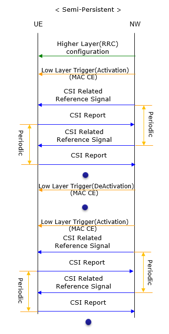
CSI Report Sequence Flow : Periodic vs Aperiodic
How these configuration works can be illustrated as below. Periodic and Aperiodic method would be obvious as shown below. Semi-Persistent can be regarded as a kind of mix of Periodic and Aperiodic. The first cycle would be similar to aperiodic, but once the cycle is triggered the CSI RS transmission and CSI Report would happen periodically.
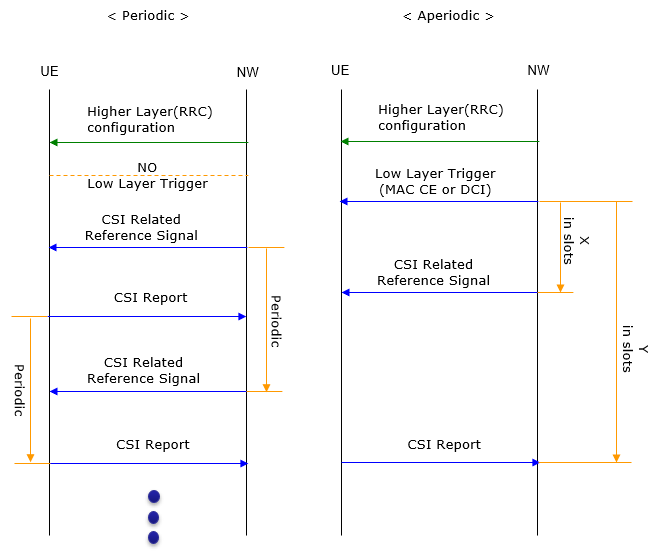
- aperiodic CSI-RS timing offset X refers to the time gap between aperiodic CSI-RS triggering and aperiodic CSI-RS transmission with regard to the number of slots
- aperiodic CSI reporting timing offset Y refers to the time gap between aperiodic CSI reporting triggering and aperiodic CSI reporting with regard to the number of slots.
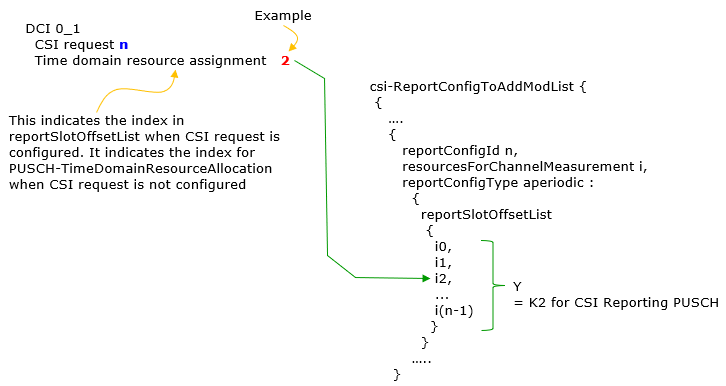
Timing offset Y for semi persistent reporting using PUSCH. This field lists the allowed offset values. This list must have the same number of entries as the pusch-TimeDomainAllocationList in PUSCH-Config. A particular value is indicated in DCI. The network indicates in the DCI field of the UL grant, which of the configured report slot offsets the UE shall apply. The DCI value 0 corresponds to the first report slot offset in this list, the DCI value 1 corresponds to the second report slot offset in this list, and so on. The first report is transmitted in slot n+Y, second report in n+Y+P, where P is the configured periodicity. Timing offset Y for aperiodic reporting using PUSCH. This field lists the allowed offset values. This list must have the same number of entries as the pusch-TimeDomainAllocationList in PUSCH-Config. A particular value is indicated in DCI. The network indicates in the DCI field of the UL grant, which of the configured report slot offsets the UE shall apply. The DCI value 0 corresponds to the first report slot offset in this list, the DCI value 1 corresponds to the second report slot offset in this list, and so on (see TS 38.214, clause 6.1.2.1).
The periodicity shown in the diagram is configured by RRC message. Depending on the physical channel and report periodicity type, different RRC parameter is used for the periodicity as shown in the following table.
|
Report Periodicity Type |
Report Physical Channel |
RRC Parameter to determin the periodicty |
| Periodic |
PUCCH |
reportSlotConfig |
| Semi-Persistent |
PUCCH |
reportSlotConfig |
| Semi-Persistent |
PUSCH |
reportSlotOffsetList |
How long does it take for UE to compute CSI measurement result ?
When Network triggers CSI Report request, UE is not able to compute the result and report right away. UE needs a certain amount of time to perform the measurement and calculate the result. The amount of time that UE needs for CSI report is described in 38.214 - 5.4 and following illustration is my interpretation of the specification.
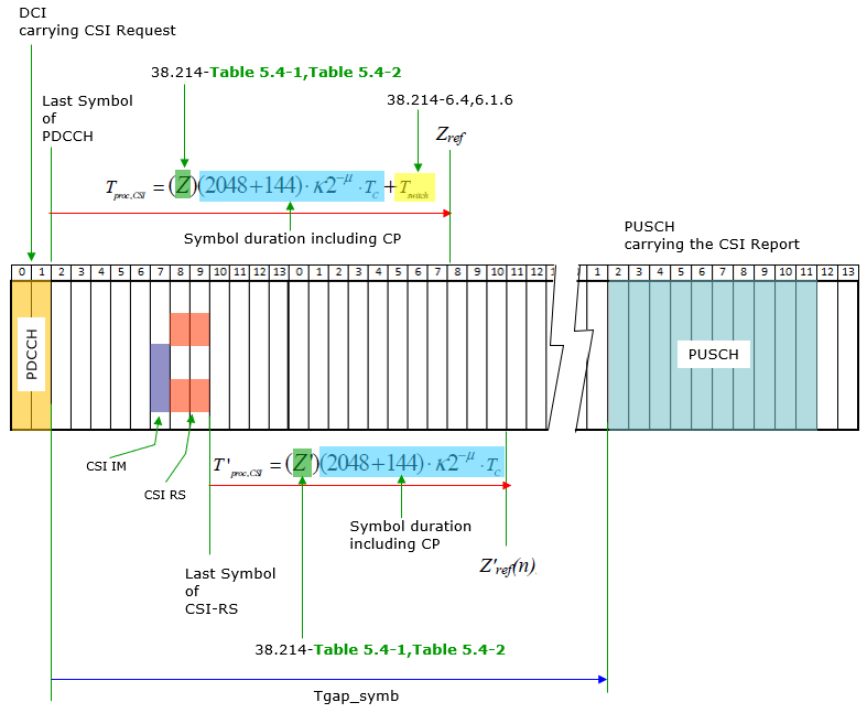
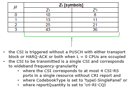
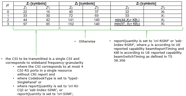
Z, Z' in the above illustration are from following tables. Which table or which columns in the table to be applied is determined by the condition described below each table.
< 38.214-Table 5.4-1: CSI computation delay requirement 1 >
< 38.214-Table 5.4-2: CSI computation delay requirement 2 >
How to configure Aperiodic Report Trigger ?
In case of Aperiodic report, the report is triggered by DCI only in some case or by the combination of MAC CE + DCI in some other case. In theory, it may sound simple.. yes.. just triggering itself is simple, but configuring the trigger condition is quite complicated and confusing which involves the interplay of many different part.
Followings are the components that are involved in the trigger configuration and triggering process.
I know this is confusing, if you think my explanation is too confusing.. refer to 38.214-5.2.1.5.1 as stated below. Hope this sound clearer -:).
When the number of configured CSI triggering states in CSI-AperiodicTriggerStateList is greater than 2^(NTS) −1 , where NTS is the number of bits in the DCI CSI request field, the UE receives a subselection indication, as described in subclause 38.321 6.1.3.13 (Aperiodic CSI Trigger State Subselection MAC CE) used to map up to 2NTS −1 trigger states to the codepoints of the CSI request field in DCI. NTS is configured by the higher layer parameter reportTriggerSize where NTS ∈{0,1, 2,3, 4,5,6}
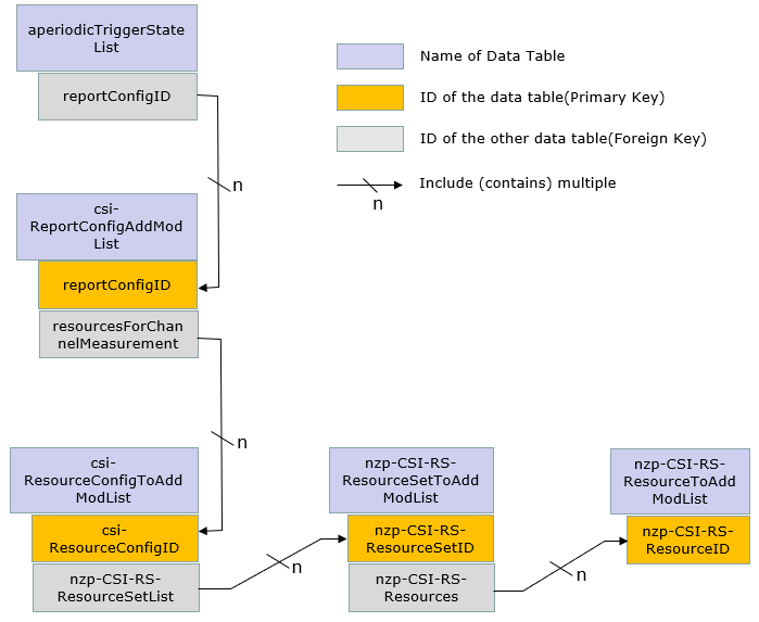
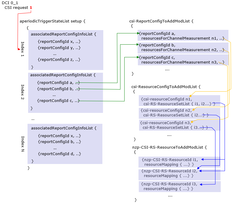
Following is an example showing how DCI 0_1 triggers an aperiodic report. As you see here, one CSI request can trigger only one associatedReportConfigInfoList, but associatedReportConfigInfoList can be associated with one or more reportConfig which results in triggering one or multiple reports. Usually this part of RRC tend to be very long and you would need some practice to get a big picture out of a real rrc message. I think the relational diagram shown below would help you get the big picture out of real RRC message.
RRC Parameters for Aperiodic Trigger
: Followings are RRC Parameters mentioned in the description above.
CSI-MeasConfig ::= SEQUENCE {
   ...
   reportTriggerSize                        INTEGER (0..6) OPTIONAL,
   aperiodicTriggerStateList                SetupRelease { CSI-AperiodicTriggerStateList },
   ...
}

CSI-AperiodicTriggerStateList ::= SEQUENCE (SIZE (1..maxNrOfCSI-AperiodicTriggers))
                                     OF CSI-AperiodicTriggerState

CSI-AperiodicTriggerState ::= SEQUENCE {
   associatedReportConfigInfoList      SEQUENCE (SIZE(1..maxNrofReportConfigPerAperiodicTrigger))
                                             OF CSI-AssociatedReportConfigInfo,
   ...
}

CSI-AssociatedReportConfigInfo ::= SEQUENCE {
   reportConfigId                     CSI-ReportConfigId,
   resourcesForChannel                CHOICE {
      nzp-CSI-RS SEQUENCE {
         resourceSet                  INTEGER (1..maxNrofNZP-CSI-RS-ResourceSetsPerConfig),
         qcl-info                     SEQUENCE (SIZE(1..maxNrofAP-CSI-RS-ResourcesPerSet))
                                             OF TCI-StateId OPTIONAL -- Cond Aperiodic
      },
      csi-SSB-ResourceSet             INTEGER (1..maxNrofCSI-SSB-ResourceSetsPerConfig)
   },
   csi-IM-ResourcesForInterference        INTEGER(1..maxNrofCSI-IM-ResourceSetsPerConfig),
   nzp-CSI-RS-ResourcesForInterference    INTEGER (1..maxNrofNZP-CSI-RS-ResourceSetsPerConfig)
   ...
}
In short, this indicates the index (starting from 1) of CSI-ReportConfig (indicated by resourcesForChannelMeasuremen of the associated ReportConfig) -> CSI-ResourceConfig -> Elements for resourcesForChannelMeasurement -> nzp-CSI-RS-ResourceSetList
In short,
- this is the list of references of BWP-Downlink -> PDSCH-Config -> tci-StatesToAddModList
- the position in this list corresponds to positions in NZP-CSI-RS-ResourceSet (indicated by nzp-CSI-RS-ResourcesforChannel of the associated ReportConfig) -> nzp-CSI-RS-Resources (First entry in qcl-info-forChannel corresponds to first entry in nzp-CSI-RS-Resources of that NZP-CSI-RS-ResourceSet, second entry in qcl-info-forChannel corresponds to second entry in nzp-CSI-RS-Resources, and so on)
In short, this indicates the Entry number in CSI-ResourceConfig (indicated by resourcesForChannelMeasurement of the associated ReportConfig) -> csi-SSB-ResourceSetList
In short, this indicates the Entry number in CSI-ResourceConfig(indicated by csi-IM-ResourcesForInterference of the associated ReportConfig) ->CSI-IM-ResourceSetList
In short, this indicates the Entry number in CSI-ResourceConfig (indicated by nzp-CSI-RSResourcesForInterference of the associated ReportConfig) -> nzp-CSI-RS-ResourceSetList
Since CSI-AssociatedReportConfigInfo is associated with reportConfig element and ResourceConfig elements, following digrams would help you to get some big picture.
Following is the general structure of CSI-ReportConfig. CSI-ReportConfig is made up of various resourceSets as shown below. The green arrow indicates a specific resourceSetId of a ResourceSetList. For example, the value c_i indicates a nzp-CSI-RS-ResourceSet defined within nzp-CSI-RS-ResourceSetToAddModList.

RRC Parameters for CSI Report
PDSCH-Config ::= SEQUENCE { dataScramblingIdentityPDSCH INTEGER (0..1007) OPTIONAL, dmrs-DownlinkForPDSCH-MappingTypeA SetupRelease { DMRS-DownlinkConfig } OPTIONAL, dmrs-DownlinkForPDSCH-MappingTypeB SetupRelease { DMRS-DownlinkConfig } OPTIONAL, tci-StatesToAddModList SEQUENCE (SIZE(1..maxNrofTCI-States)) OF TCI-State OPTIONAL, -- Need N tci-StatesToReleaseList SEQUENCE (SIZE(1..maxNrofTCI-States)) OF TCI-StateId OPTIONAL, -- Need N vrb-ToPRB-Interleaver ENUMERATED {n2, n4}, resourceAllocation ENUMERATED { resourceAllocationType0, resourceAllocationType1, dynamicSwitch}, pdsch-AllocationList SEQUENCE (SIZE(1..maxNrofDL-Allocations)) OF PDSCH-TimeDomainResourceAllocation , pdsch-AggregationFactor ENUMERATED { n2, n4, n8 } OPTIONAL, rateMatchPatternToAddModList SEQUENCE (SIZE (1..maxNrofRateMatchPatterns)) OF RateMatchPattern OPTIONAL, -- Need N rateMatchPatternToReleaseList SEQUENCE (SIZE (1..maxNrofRateMatchPatterns)) OF RateMatchPatternId OPTIONAL, -- Need N rateMatchPatternGroup1 SEQUENCE (SIZE (1..maxNrofRateMatchPatterns)) OF RateMatchPatternId OPTIONAL, -- Need R rateMatchPatternGroup2 SEQUENCE (SIZE (1..maxNrofRateMatchPatterns)) OF RateMatchPatternId OPTIONAL, -- Need R rbg-Size ENUMERATED {config1, config2}, mcs-Table ENUMERATED {qam64, qam256}, maxNrofCodeWordsScheduledByDCI ENUMERATED {n1, n2} OPTIONAL, -- Need R prb-BundlingType CHOICE { static SEQUENCE { bundleSize ENUMERATED { n4, wideband } OPTIONAL }, dynamic SEQUENCE { bundleSizeSet1 ENUMERATED { n4, wideband, n2-wideband, n4-wideband } OPTIONAL, -- Need S bundleSizeSet2 ENUMERATED { n4, wideband } OPTIONAL -- Need S } }, zp-CSI-RS-ResourceToAddModList SEQUENCE (SIZE (1..maxNrofZP-CSI-RS-Resources)) OF ZP-CSI-RS-Resource OPTIONAL, -- Need N zp-CSI-RS-ResourceToReleaseList SEQUENCE (SIZE (1..maxNrofZP-CSI-RS-Resources)) OF ZP-CSI-RS-ResourceId OPTIONAL, -- Need M aperiodic-ZP-CSI-RS-ResourceSetsToAddModList SEQUENCE (SIZE (1..maxNrofZP-CSI-RS-Sets)) OF ZP-CSI-RS-ResourceSet OPTIONAL, -- Need N aperiodic-ZP-CSI-RS-ResourceSetsToReleaseList SEQUENCE (SIZE (1..maxNrofZP-CSI-RS-Sets)) OF ZP-CSI-RS-ResourceSetId OPTIONAL, -- Need N sp-ZP-CSI-RS-ResourceSetsToAddModList SEQUENCE (SIZE (1..maxNrofZP-CSI-RS-Sets)) OF ZP-CSI-RS-ResourceSet OPTIONAL, -- Need N sp-ZP-CSI-RS-ResourceSetsToReleaseList SEQUENCE (SIZE (1..maxNrofZP-CSI-RS-Sets)) OF ZP-CSI-RS-ResourceSetId OPTIONAL, -- Need N ... } CSI-MeasConfig ::= SEQUENCE { nzp-CSI-RS-ResourceToAddModList SEQUENCE (SIZE (1..maxNrofNZP-CSI-RS-Resources)) OF NZP-CSI-RS-Resource OPTIONAL, nzp-CSI-RS-ResourceToReleaseList SEQUENCE (SIZE (1..maxNrofNZP-CSI-RS-Resources)) OF NZP-CSI-RS-ResourceId OPTIONAL, nzp-CSI-RS-ResourceSetToAddModList SEQUENCE (SIZE (1..maxNrofNZP-CSI-RS-ResourceSets)) OF NZP-CSI-RS-ResourceSet OPTIONAL, nzp-CSI-RS-ResourceSetToReleaseList SEQUENCE (SIZE (1..maxNrofNZP-CSI-RS-ResourceSets)) OF NZP-CSI-RS-ResourceSetId OPTIONAL, csi-IM-ResourceToAddModList SEQUENCE (SIZE (1..maxNrofCSI-IM-Resources)) OF CSI-IM-Resource OPTIONAL, csi-IM-ResourceToReleaseList SEQUENCE (SIZE (1..maxNrofCSI-IM-Resources)) OF CSI-IM-ResourceId OPTIONAL, csi-IM-ResourceSetToAddModList SEQUENCE (SIZE (1..maxNrofCSI-IM-ResourceSets)) OF CSI-IM-ResourceSet OPTIONAL, csi-IM-ResourceSetToReleaseList SEQUENCE (SIZE (1..maxNrofCSI-IM-ResourceSets)) OF CSI-IM-ResourceSetId OPTIONAL, csi-SSB-ResourceSetToAddModList SEQUENCE (SIZE (1..maxNrofCSI-SSB-ResourceSets)) OF CSI-SSB-ResourceSet OPTIONAL, csi-SSB-ResourceSetToAddReleaseList SEQUENCE (SIZE (1..maxNrofCSI-SSB-ResourceSets)) OF CSI-SSB-ResourceSetId OPTIONAL, csi-ResourceConfigToAddModList SEQUENCE (SIZE (1..maxNrofCSI-ResourceConfigurations)) OF CSI-ResourceConfig OPTIONAL, csi-ResourceConfigToReleaseList SEQUENCE (SIZE (1..maxNrofCSI-ResourceConfigurations)) OF CSI-ResourceConfigId OPTIONAL, csi-ReportConfigToAddModList SEQUENCE (SIZE (1..maxNrofCSI-ReportConfigurations)) OF CSI-ReportConfig OPTIONAL, csi-ReportConfigToReleaseList SEQUENCE (SIZE (1..maxNrofCSI-ReportConfigurations)) OF CSI-ReportConfigId OPTIONAL, reportTriggerSize INTEGER (0..6) OPTIONAL, aperiodicTriggerStateList SetupRelease { CSI-AperiodicTriggerStateList }, semiPersistentOnPUSCH-TriggerStateList SetupRelease { CSI-SemiPersistentOnPUSCH-TriggerStateList } OPTIONAL, ... } TCI-State ::= SEQUENCE { tci-StateId TCI-StateId, qcl-Type1 QCL-Info, qcl-Type2 QCL-Info OPTIONAL, -- Need R ... } QCL-Info ::= SEQUENCE { cell ServCellIndex OPTIONAL, -- Need R bwp-Id BWP-Id OPTIONAL, -- Cond CSI-RS-Indicated referenceSignal CHOICE { csi-rs NZP-CSI-RS-ResourceId, ssb SSB-Index }, qcl-Type ENUMERATED {typeA, typeB, typeC, typeD}, ... } ZP-CSI-RS-Resource ::= SEQUENCE { zp-CSI-RS-ResourceId ZP-CSI-RS-ResourceId, resourceMapping CSI-RS-ResourceMapping, periodicityAndOffset CSI-ResourcePeriodicityAndOffset OPTIONAL, ... } ZP-CSI-RS-ResourceSet ::= SEQUENCE { zp-CSI-RS-ResourceSetId ZP-CSI-RS-ResourceSetId, zp-CSI-RS-ResourceIdList SEQUENCE (SIZE(1..maxNrofZP-CSI-RS-ResourcesPerSet)) OF ZP-CSI-RS-ResourceId, ... } NZP-CSI-RS-Resource ::= SEQUENCE { nzp-CSI-RS-ResourceId NZP-CSI-RS-ResourceId, resourceMapping CSI-RS-ResourceMapping, powerControlOffset INTEGER (-8..15), powerControlOffsetSS ENUMERATED{db-3, db0, db3, db6} OPTIONAL, -- Need R scramblingID ScramblingId, periodicityAndOffset CSI-ResourcePeriodicityAndOffset OPTIONAL,- qcl-InfoPeriodicCSI-RS TCI-StateId OPTIONAL, -- Cond Periodic ... } NZP-CSI-RS-ResourceSet ::= SEQUENCE { nzp-CSI-ResourceSetId NZP-CSI-RS-ResourceSetId, nzp-CSI-RS-Resources SEQUENCE (SIZE (1..maxNrofNZP-CSI-RS-ResourcesPerSet)) OF NZP-CSI-RS-ResourceId, repetition ENUMERATED { on, off } OPTIONAL, aperiodicTriggeringOffset INTEGER(0..4) OPTIONAL, trs-Info ENUMERATED {true} OPTIONAL, ... } CSI-RS-ResourceMapping ::= SEQUENCE { frequencyDomainAllocation CHOICE { row1 BIT STRING (SIZE (4)), row2 BIT STRING (SIZE (12)), row4 BIT STRING (SIZE (3)), other BIT STRING (SIZE (6)) }, nrofPorts ENUMERATED {p1,p2,p4,p8,p12,p16,p24,p32}, firstOFDMSymbolInTimeDomain INTEGER (0..13), firstOFDMSymbolInTimeDomain2 INTEGER (2..12) OPTIONAL, -- Need R cdm-Type ENUMERATED {noCDM, fd-CDM2, cdm4-FD2-TD2, cdm8-FD2-TD4}, density CHOICE { dot5 ENUMERATED {evenPRBs, oddPRBs}, one NULL, three NULL, spare NULL }, freqBand CSI-FrequencyOccupation, ... } CSI-ResourcePeriodicityAndOffset ::= CHOICE { slots4 INTEGER (0..3), slots5 INTEGER (0..4), slots8 INTEGER (0..7), slots10 INTEGER (0..9), slots16 INTEGER (0..15), slots20 INTEGER (0..19), slots32 INTEGER (0..31), slots40 INTEGER (0..39), slots64 INTEGER (0..63), slots80 INTEGER (0..79), slots160 INTEGER (0..159), slots320 INTEGER (0..319), slots640 INTEGER (0..639) } CSI-FrequencyOccupation ::= SEQUENCE { startingRB INTEGER (0..maxNrofPhysicalResourceBlocks-1), nrofRBs INTEGER (24..maxNrofPhysicalResourceBlocksPlus1), ... } CSI-IM-Resource ::= SEQUENCE { csi-IM-ResourceId CSI-IM-ResourceId, csi-IM-ResourceElementPattern CHOICE { pattern0 SEQUENCE { subcarrierLocation-p0 ENUMERATED { s0, s2, s4, s6, s8, s10 }, symbolLocation-p0 INTEGER (0..12) }, pattern1 SEQUENCE { subcarrierLocation-p1 ENUMERATED { s0, s4, s8 }, symbolLocation-p1 INTEGER (0..13) } } OPTIONAL, -- Need M freqBand CSI-FrequencyOccupation OPTIONAL, periodicityAndOffset CSI-ResourcePeriodicityAndOffset OPTIONAL, PeriodicOrSemiPersistent ... } CSI-IM-ResourceSet ::= SEQUENCE { csi-IM-ResourceSetId CSI-IM-ResourceSetId, csi-IM-Resources SEQUENCE (SIZE(1..maxNrofCSI-IM-ResourcesPerSet)) OF CSI-IM-ResourceId, ... } CSI-SSB-ResourceSet ::= SEQUENCE { csi-SSB-ResourceSetId CSI-SSB-ResourceSetId, csi-SSB-ResourceList SEQUENCE (SIZE(1..maxNrofCSI-SSB-ResourcePerSet)) OF SSB-Index, ... } CSI-ResourceConfig ::= SEQUENCE { csi-ResourceConfigId CSI-ResourceConfigId, csi-RS-ResourceSetList CHOICE { nzp-CSI-RS-SSB SEQUENCE { nzp-CSI-RS-ResourceSetList SEQUENCE (SIZE (1..maxNrofNZP-CSI-RS-ResourceSetsPerConfig)) OF NZP-CSI-RS-ResourceSetId OPTIONAL, csi-SSB-ResourceSetList SEQUENCE (SIZE (1..maxNrofCSI-SSB-ResourceSetsPerConfig)) OF CSI-SSB-ResourceSetId OPTIONAL }, csi-IM-ResourceSetList SEQUENCE (SIZE (1..maxNrofCSI-IM-ResourceSetsPerConfig)) OF CSI-IM-ResourceSetId }, bwp-Id BWP-Id, resourceType ENUMERATED { aperiodic, semiPersistent, periodic }, ... } CSI-ReportConfig ::= SEQUENCE { reportConfigId CSI-ReportConfigId, carrier ServCellIndex OPTIONAL, resourcesForChannelMeasurement CSI-ResourceConfigId, csi-IM-ResourcesForInterference CSI-ResourceConfigId OPTIONAL, nzp-CSI-RS-ResourcesForInterference CSI-ResourceConfigId OPTIONAL, reportConfigType CHOICE { periodic SEQUENCE { reportSlotConfig CSI-ReportPeriodicityAndOffset, pucch-CSI-ResourceList SEQUENCE (SIZE (1..maxNrofBWPs)) OF PUCCH-CSI-Resource }, semiPersistentOnPUCCH SEQUENCE { reportSlotConfig CSI-ReportPeriodicityAndOffset, pucch-CSI-ResourceList SEQUENCE (SIZE (1..maxNrofBWPs)) OF PUCCH-CSI-Resource }, semiPersistentOnPUSCH SEQUENCE { reportSlotConfig ENUMERATED {sl5, sl10, sl20, sl40, sl80, sl160, sl320}, reportSlotOffsetList SEQUENCE (SIZE (1.. maxNrofUL-Allocations)) OF INTEGER(0..32), p0alpha P0-PUSCH-AlphaSetId }, aperiodic SEQUENCE { reportSlotOffsetList SEQUENCE (SIZE (1..maxNrofUL-Allocations)) OF INTEGER(0..32) } }, reportQuantity CHOICE { // Check this for the meaning of this IE none NULL, cri-RI-PMI-CQI NULL, cri-RI-i1 NULL, cri-RI-i1-CQI SEQUENCE { pdsch-BundleSizeForCSI ENUMERATED {n2, n4} OPTIONAL }, cri-RI-CQI NULL, cri-RSRP NULL, ssb-Index-RSRP NULL, cri-RI-LI-PMI-CQI NULL }, reportFreqConfiguration SEQUENCE { cqi-FormatIndicator ENUMERATED { widebandCQI, subbandCQI } OPTIONAL, pmi-FormatIndicator ENUMERATED { widebandPMI, subbandPMI } OPTIONAL, csi-ReportingBand CHOICE { // Check this for the meaning of this IE subbands3 BIT STRING(SIZE(3)), subbands4 BIT STRING(SIZE(4)), subbands5 BIT STRING(SIZE(5)), subbands6 BIT STRING(SIZE(6)), subbands7 BIT STRING(SIZE(7)), subbands8 BIT STRING(SIZE(8)), subbands9 BIT STRING(SIZE(9)), subbands10 BIT STRING(SIZE(10)), subbands11 BIT STRING(SIZE(11)), subbands12 BIT STRING(SIZE(12)), subbands13 BIT STRING(SIZE(13)), subbands14 BIT STRING(SIZE(14)), subbands15 BIT STRING(SIZE(15)), subbands16 BIT STRING(SIZE(16)), subbands17 BIT STRING(SIZE(17)), subbands18 BIT STRING(SIZE(18)), ..., subbands19-v1530 BIT STRING(SIZE(19)) } OPTIONAL } OPTIONAL, // Check this for the meaning of the following two IE timeRestrictionForChannelMeasurements ENUMERATED {configured, notConfigured}, timeRestrictionForInterferenceMeasurements ENUMERATED {configured, notConfigured}, codebookConfig CodebookConfig OPTIONAL, nrofCQIsPerReport ENUMERATED {n1, n2} OPTIONAL, groupBasedBeamReporting CHOICE { enabled NULL, disabled SEQUENCE { nrofReportedRS ENUMERATED {n1, n2, n3, n4} OPTIONAL } }, cqi-Table ENUMERATED {table1, table2, table3, spare1} OPTIONAL, subbandSize ENUMERATED {value1, value2}, non-PMI-PortIndication SEQUENCE (SIZE (1..maxNrofNZP-CSI-RS-ResourcesPerConfig)) OF PortIndexFor8Ranks OPTIONAL, ..., [[ semiPersistentOnPUSCH-v1530 SEQUENCE { reportSlotConfig-v1530 ENUMERATED {sl4, sl8, sl16} } OPTIONAL ]] } CSI-ReportPeriodicityAndOffset ::= CHOICE { slots4 INTEGER(0..3), slots5 INTEGER(0..4), slots8 INTEGER(0..7), slots10 INTEGER(0..9), slots16 INTEGER(0..15), slots20 INTEGER(0..19), slots40 INTEGER(0..39), slots80 INTEGER(0..79), slots160 INTEGER(0..159), slots320 INTEGER(0..319) } PUCCH-CSI-Resource ::= SEQUENCE { uplinkBandwidthPartId BWP-Id, pucch-Resource PUCCH-ResourceId } PortIndexFor8Ranks ::= CHOICE { // Check this for the meaning of this IE portIndex8 SEQUENCE{ rank1-8 PortIndex8 OPTIONAL, -- Need R rank2-8 SEQUENCE(SIZE(2)) OF PortIndex8 OPTIONAL, -- Need R rank3-8 SEQUENCE(SIZE(3)) OF PortIndex8 OPTIONAL, -- Need R rank4-8 SEQUENCE(SIZE(4)) OF PortIndex8 OPTIONAL, -- Need R rank5-8 SEQUENCE(SIZE(5)) OF PortIndex8 OPTIONAL, -- Need R rank6-8 SEQUENCE(SIZE(6)) OF PortIndex8 OPTIONAL, -- Need R rank7-8 SEQUENCE(SIZE(7)) OF PortIndex8 OPTIONAL, -- Need R rank8-8 SEQUENCE(SIZE(8)) OF PortIndex8 OPTIONAL -- Need R }, portIndex4 SEQUENCE{ rank1-4 PortIndex4 OPTIONAL, -- Need R rank2-4 SEQUENCE(SIZE(2)) OF PortIndex4 OPTIONAL, -- Need R rank3-4 SEQUENCE(SIZE(3)) OF PortIndex4 OPTIONAL, -- Need R rank4-4 SEQUENCE(SIZE(4)) OF PortIndex4 OPTIONAL -- Need R }, portIndex2 SEQUENCE{ rank1-2 PortIndex2 OPTIONAL, -- Need R rank2-2 SEQUENCE(SIZE(2)) OF PortIndex2 OPTIONAL -- Need R }, portIndex1 NULL } CodebookConfig ::= SEQUENCE { // Check this for the meaning of this IE codebookType CHOICE { type1 SEQUENCE { subType CHOICE { typeI-SinglePanel SEQUENCE { nrOfAntennaPorts CHOICE { two SEQUENCE { twoTX-CodebookSubsetRestriction BIT STRING (SIZE (6)) }, moreThanTwo SEQUENCE { n1-n2 CHOICE { two-one-TypeI-SinglePanel-Restriction BIT STRING (SIZE (8)), two-two-TypeI-SinglePanel-Restriction BIT STRING (SIZE (64)), four-one-TypeI-SinglePanel-Restriction BIT STRING (SIZE (16)), three-two-TypeI-SinglePanel-Restriction BIT STRING (SIZE (96)), six-one-TypeI-SinglePanel-Restriction BIT STRING (SIZE (24)), four-two-TypeI-SinglePanel-Restriction BIT STRING (SIZE (128)), eight-one-TypeI-SinglePanel-Restriction BIT STRING (SIZE (32)), four-three-TypeI-SinglePanel-Restriction BIT STRING (SIZE (192)), six-two-TypeI-SinglePanel-Restriction BIT STRING (SIZE (192)), twelve-one-TypeI-SinglePanel-Restriction BIT STRING (SIZE (48)), four-four-TypeI-SinglePanel-Restriction BIT STRING (SIZE (256)), eight-two-TypeI-SinglePanel-Restriction BIT STRING (SIZE (256)), sixteen-one-TypeI-SinglePanel-Restriction BIT STRING (SIZE (64)) }, typeI-SinglePanel-codebookSubsetRestriction-i2 BIT STRING (SIZE (16)) } }, typeI-SinglePanel-ri-Restriction BIT STRING (SIZE (8)) }, typeI-MultiPanel SEQUENCE { ng-n1-n2 CHOICE { two-two-one-TypeI-MultiPanel-Restriction BIT STRING (SIZE (8)), two-four-one-TypeI-MultiPanel-Restriction BIT STRING (SIZE (16)), four-two-one-TypeI-MultiPanel-Restriction BIT STRING (SIZE (8)), two-two-two-TypeI-MultiPanel-Restriction BIT STRING (SIZE (64)), two-eight-one-TypeI-MultiPanel-Restriction BIT STRING (SIZE (32)), four-four-one-TypeI-MultiPanel-Restriction BIT STRING (SIZE (16)), two-four-two-TypeI-MultiPanel-Restriction BIT STRING (SIZE (128)), four-two-two-TypeI-MultiPanel-Restriction BIT STRING (SIZE (64)) }, ri-Restriction BIT STRING (SIZE (4)) } }, codebookMode INTEGER (1..2) }, type2 SEQUENCE { subType CHOICE { typeII SEQUENCE { n1-n2-codebookSubsetRestriction CHOICE { two-one BIT STRING (SIZE (16)), two-two BIT STRING (SIZE (43)), four-one BIT STRING (SIZE (32)), three-two BIT STRING (SIZE (59)), six-one BIT STRING (SIZE (48)), four-two BIT STRING (SIZE (75)), eight-one BIT STRING (SIZE (64)), four-three BIT STRING (SIZE (107)), six-two BIT STRING (SIZE (107)), twelve-one BIT STRING (SIZE (96)), four-four BIT STRING (SIZE (139)), eight-two BIT STRING (SIZE (139)), sixteen-one BIT STRING (SIZE (128)) }, typeII-RI-Restriction BIT STRING (SIZE (2)) }, typeII-PortSelection SEQUENCE { portSelectionSamplingSize ENUMERATED {n1, n2, n3, n4} OPTIONAL, typeII-PortSelectionRI-Restriction BIT STRING (SIZE (2)) } }, phaseAlphabetSize ENUMERATED {n4, n8}, subbandAmplitude BOOLEAN, numberOfBeams ENUMERATED {two, three, four} } } } CSI-AperiodicTriggerStateList ::= SEQUENCE (SIZE (1..maxNrOfCSI-AperiodicTriggers)) OF CSI-AperiodicTriggerState CSI-AperiodicTriggerState ::= SEQUENCE { associatedReportConfigInfoList SEQUENCE (SIZE(1..maxNrofReportConfigPerAperiodicTrigger)) OF CSI-AssociatedReportConfigInfo, ... } CSI-AssociatedReportConfigInfo ::= SEQUENCE { reportConfigId CSI-ReportConfigId, resourcesForChannel CHOICE { nzp-CSI-RS SEQUENCE { resourceSet INTEGER (1..maxNrofNZP-CSI-RS-ResourceSetsPerConfig), qcl-info SEQUENCE (SIZE(1..maxNrofAP-CSI-RS-ResourcesPerSet)) OF TCI-StateId OPTIONAL -- Cond Aperiodic }, csi-SSB-ResourceSet INTEGER (1..maxNrofCSI-SSB-ResourceSetsPerConfig) }, csi-IM-ResourcesForInterference INTEGER(1..maxNrofCSI-IM-ResourceSetsPerConfig), nzp-CSI-RS-ResourcesForInterference INTEGER (1..maxNrofNZP-CSI-RS-ResourceSetsPerConfig) ... } CSI-SemiPersistentOnPUSCH-TriggerStateList ::= SEQUENCE(SIZE (1..maxNrOfSemiPersistentPUSCH-Triggers)) OF CSI-SemiPersistentOnPUSCH-TriggerState CSI-SemiPersistentOnPUSCH-TriggerState ::= SEQUENCE { associatedReportConfigInfo CSI-ReportConfigId, ... } MeasurementReport ::= SEQUENCE { criticalExtensions CHOICE { measurementReport MeasurementReport-IEs, criticalExtensionsFuture SEQUENCE {} } } MeasurementReport-IEs ::= SEQUENCE { measResults MeasResults, lateNonCriticalExtension OCTET STRING OPTIONAL, nonCriticalExtension SEQUENCE{} OPTIONAL } MeasResults ::= SEQUENCE { measId MeasId, measResultServingMOList MeasResultServMOList, measResultNeighCells CHOICE { measResultListNR MeasResultListNR, ..., measResultListEUTRA MeasResultListEUTRA } OPTIONAL, ... } MeasResultServMOList ::= SEQUENCE (SIZE (1..maxNrofServingCells)) OF MeasResultServMO MeasResultServMO ::= SEQUENCE { servCellId ServCellIndex, measResultServingCell MeasResultNR, measResultBestNeighCell MeasResultNR OPTIONAL, ... } MeasResultListNR ::= SEQUENCE (SIZE (1..maxCellReport)) OF MeasResultNR MeasResultNR ::= SEQUENCE { physCellId PhysCellId OPTIONAL, measResult SEQUENCE { cellResults SEQUENCE{ resultsSSB-Cell MeasQuantityResults OPTIONAL, resultsCSI-RS-Cell MeasQuantityResults OPTIONAL }, rsIndexResults SEQUENCE{ resultsSSB-Indexes ResultsPerSSB-IndexList OPTIONAL, resultsCSI-RS-Indexes ResultsPerCSI-RS-IndexList OPTIONAL } OPTIONAL }, ..., [[ cgi-Info CGI-Info OPTIONAL ]] } MeasResultListEUTRA ::= SEQUENCE (SIZE (1..maxCellReport)) OF MeasResultEUTRA MeasResultEUTRA ::= SEQUENCE { physCellId PhysCellId, measResult MeasQuantityResultsEUTRA, cgi-Info SEQUENCE { cgi-info-EPC SEQUENCE { cgi-info-EPC-legacy CellAccessRelatedInfo-EUTRA-EPC, cgi-info-EPC-list SEQUENCE (SIZE (1..maxPLMN)) OF CellAccessRelatedInfo-EUTRA-EPC OPTIONAL } OPTIONAL, cgi-info-5GC SEQUENCE (SIZE (1..maxPLMN)) OF CellAccessRelatedInfo-EUTRA-5GC OPTIONAL, freqBandIndicator FreqBandIndicatorEUTRA, multiBandInfoList MultiBandInfoListEUTRA OPTIONAL, freqBandIndicatorPriority ENUMERATED {true} OPTIONAL } OPTIONAL, ... } CellAccessRelatedInfo-EUTRA-EPC ::= SEQUENCE { plmn-IdentityList-eutra-epc PLMN-IdentityList-EUTRA-EPC, trackingAreaCode-eutra-epc BIT STRING (SIZE (16)), cellIdentity-eutra-epc BIT STRING (SIZE (28)) } PLMN-IdentityList-EUTRA-EPC::= SEQUENCE (SIZE (1..maxPLMN)) OF PLMN-Identity PLMN-Identity ::= SEQUENCE { mcc MCC OPTIONAL, -- Cond MCC mnc MNC } CellAccessRelatedInfo-EUTRA-5GC ::= SEQUENCE { plmn-IdentityList-eutra-5gc PLMN-IdentityList-EUTRA-5GC, trackingAreaCode-eutra-5gc TrackingAreaCode, ranac-5gc RAN-AreaCode OPTIONAL, cellIdentity-eutra-5gc CellIdentity-EUTRA-5GC } PLMN-IdentityList-EUTRA-5GC::= SEQUENCE (SIZE (1..maxPLMN)) OF PLMN-Identity-EUTRA-5GC PLMN-Identity-EUTRA-5GC ::= CHOICE { plmn-Identity-EUTRA-5GC PLMN-Identity, plmn-index INTEGER (1..maxPLMN) } CellIdentity-EUTRA-5GC ::= CHOICE { cellIdentity-EUTRA BIT STRING (SIZE (28)), cellId-index INTEGER (1..maxPLMN) } MultiBandInfoListEUTRA ::= SEQUENCE (SIZE (1..maxMultiBands)) OF FreqBandIndicatorEUTRA MeasQuantityResults ::= SEQUENCE { rsrp RSRP-Range OPTIONAL, rsrq RSRQ-Range OPTIONAL, sinr SINR-Range OPTIONAL } MeasQuantityResultsEUTRA ::= SEQUENCE { rsrp RSRP-RangeEUTRA OPTIONAL, rsrq RSRQ-RangeEUTRA OPTIONAL, sinr SINR-RangeEUTRA OPTIONAL } ResultsPerSSB-IndexList::= SEQUENCE (SIZE (1..maxNrofIndexesToReport2)) OF ResultsPerSSB-Index ResultsPerSSB-Index ::= SEQUENCE { ssb-Index SSB-Index, ssb-Results MeasQuantityResults OPTIONAL } ResultsPerCSI-RS-IndexList::= SEQUENCE (SIZE (1..maxNrofIndexesToReport2)) OF ResultsPerCSI-RS-Index ResultsPerCSI-RS-Index ::= SEQUENCE { csi-RS-Index CSI-RS-Index, csi-RS-Results MeasQuantityResults OPTIONAL } maxNrofIndexesToReport INTEGER ::= 32 maxNrofIndexesToReport2 INTEGER ::= 64 maxMultiBands INTEGER ::= 8 maxCellReport INTEGER ::= 8 maxNrofServingCells INTEGER ::= 32
RRC Examples
Personally I don't think it is easy to come up with any RRC configuration Example for CSI measurement / BeamManagement that works for every UE. Even if you have understandins on every details of each compoments related to CSI Report (i.e, 38.211, 38.214, 38.331), it is just too complicated (in many cases not clear/confusing in 3GPP spec documentation) to consolidate all of those individual components to make the whole report process work as expected. Even with exact same configuration, you may experience that it would work with some UE but does not work with other UE and find no clear technical reasons for the different results.
In this case, I think it would be a good idea to try with configurations used in Protocol Conformance test. Even if it may look a little bit oversimplified comparing to what you see in real network, you may expect that the conformance configuration should work for most of commercialized UE.
Basic Template
Following is basic templates of CSI Report configuration from 38.508-1, v16.7. From these basic template, many variations are derived depending on test purpose.
< 38.508-1 Table 4.6.3-38: CSI-MeasConfig >
|
CSI-MeasConfig::= SEQUENCE { |
|||
|
nzp-CSI-RS-ResourceToAddModList SEQUENCE { |
1 entry |
||
|
NZP-CSI-RS-Resource[1] |
entry 1 |
||
|
} |
|||
|
nzp-CSI-RS-ResourceToReleaseList |
Not present |
||
|
nzp-CSI-RS-ResourceSetToAddModList SEQUENCE { |
1 entry |
||
|
NZP-CSI-RS-ResourceSet[1] |
entry 1 |
||
|
} |
|||
|
nzp-CSI-RS-ResourceSetToReleaseList |
Not present |
||
|
csi-IM-ResourceToAddModList SEQUENCE { |
1 entry |
||
|
CSI-IM-Resource[1] |
entry 1 |
||
|
} |
|||
|
csi-IM-ResourceToReleaseList |
Not present |
||
|
csi-IM-ResourceSetToAddModList SEQUENCE { |
1 entry |
||
|
CSI-IM-ResourceSet[1] |
|||
|
} |
|||
|
csi-IM-ResourceSetToReleaseList |
Not present |
||
|
csi-SSB-ResourceSetToAddModList SEQUENCE { |
1 entry |
||
|
CSI-SSB-ResourceSet[1] |
CSI-SSB-ResourceSet |
entry 1 |
|
|
} |
|||
|
csi-SSB-ResourceSetToAddReleaseList |
Not present |
||
|
csi-ResourceConfigToAddModList SEQUENCE { |
1 entry |
||
|
CSI-ResourceConfig[1] |
entry 1 |
||
|
} |
|||
|
csi-ResourceConfigToReleaseList |
Not present |
||
|
csi-ReportConfigToAddModList |
1 entry |
||
|
CSI-ReportConfig[1] |
entry 1 |
||
|
} |
|||
|
csi-ReportConfigToReleaseList |
Not present |
||
|
reportTriggerSize |
0 |
||
|
aperiodicTriggerStateList SetupRelease { |
|||
|
setup |
|||
|
} |
|||
|
semiPersistentOnPUSCH-TriggerStateList |
Not present |
||
|
} |
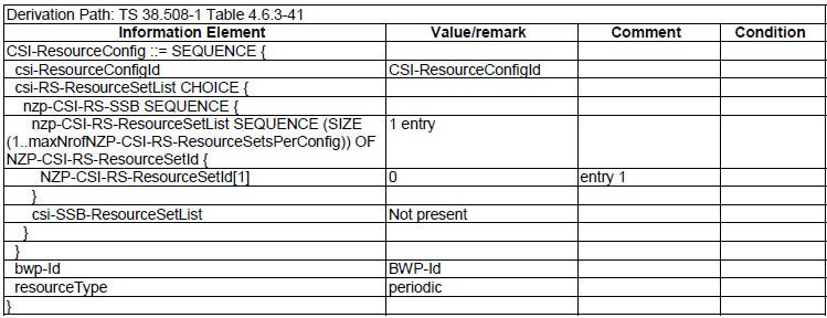
< 38.508-1 Table 4.6.3-41: CSI-ResourceConfig >
|
CSI-ResourceConfig ::= SEQUENCE { |
|||
|
csi-ResourceConfigId |
CSI-ResourceConfigId |
||
|
csi-RS-ResourceSetList CHOICE { |
|||
|
nzp-CSI-RS-SSB SEQUENCE { |
|||
|
nzp-CSI-RS-ResourceSetList SEQUENCE (SIZE (1..maxNrofNZP-CSI-RS-ResourceSetsPerConfig)) OF { |
2 entries |
||
|
NZP-CSI-RS-ResourceSetId[0] |
0 |
entry 1 |
|
|
NZP-CSI-RS-ResourceSetId[1] |
1 |
entry 2 |
|
|
} |
|||
|
csi-SSB-ResourceSetList |
Not present |
||
|
} |
|||
|
} |
|||
|
bwp-Id |
BWP-Id |
||
|
resourceType |
periodic |
||
|
} |
< 38.508-1 Table 4.6.3-32: CSI-AperiodicTriggerStateList >
|
Information Element |
Value/Remark |
Comment |
FR1 |
FR2 |
|
CSI-AperiodicTriggerStateList ::= SEQUENCE (SIZE (1..maxNrOfCSI-AperiodicTriggers)) OF CSI-AperiodicTriggerState{ |
1 entry |
|
||
|
CSI-AperiodicTriggerState[1] SEQUENCE { |
|
entry 1 |
||
|
associatedReportConfigInfoList SEQUENCE (SIZE(1..maxNrofReportConfigPerAperiodicTrigger)) OF CSI-AssociatedReportConfigInfo { |
1 entry |
|
|
|
|
CSI-AssociatedReportConfigInfo[1] SEQUENCE { |
|
entry 1 |
|
|
|
reportConfigId[1] |
CSI-ReportConfigId |
|
||
|
resourcesForChannel[1] CHOICE { |
|
|||
|
nzp-CSI-RS SEQUENCE { |
|
|||
|
resourceSet |
|
|
8 |
16 |
|
qcl-info SEQUENCE (SIZE(1..maxNrofAP-CSI-RS-ResourcesPerSet)) OF { |
1 entry |
|
||
|
TCI-StateId[1] |
TCI-StateId |
entry 1 |
||
|
} |
|
|||
|
} |
|
|||
|
} |
|
|||
|
csi-IM-ResourcesforInteference[1] |
|
|
8 |
16 |
|
nzp-CSI-RS-ResourcesforInterference[1] |
|
|
8 |
16 |
|
} |
|
|||
|
} |
|
< 38.508-1 Table 4.6.3-85: NZP-CSI-RS-Resource >
|
NZP-CSI-RS-Resource ::= SEQUENCE { |
|||
|
nzp-CSI-RS-ResourceId |
NZP-CSI-RS-ResourceId |
||
|
resourceMapping |
|||
|
powerControlOffset |
-3 |
||
|
powerControlOffsetSS |
Not present |
||
|
scramblingID |
ScramblingId |
||
|
periodicityAndOffset |
|||
|
qcl-InfoPeriodicCSI-RS |
TCI-StateId |
||
|
} |
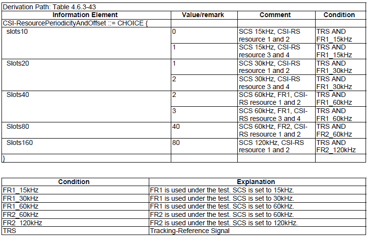
< 38.508-1 Table 4.6.3-43: CSI-ResourcePeriodicityAndOffset >
|
CSI-ResourcePeriodicityAndOffset ::= CHOICE { |
|
|
|
|
slots80 |
10 |
FR1 |
|
|
slots320 |
40 |
FR2 |
|
|
} |
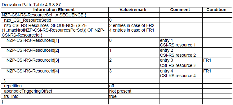
< 38.508-1 Table 4.6.3-87: NZP-CSI-RS-ResourceSet>
|
|
|
FR1 |
FR2 |
|
NZP-CSI-RS-ResourceSet ::= SEQUENCE { |
|||
|
nzp-CSI-ResourceSetId |
NZP-CSI-RS-ResourceSetId |
||
|
nzp-CSI-RS-Resources SEQUENCE (SIZE (1..maxNrofNZP-CSI-RS-ResourcesPerSet)) OF { |
[1 entry] |
||
|
NZP-CSI-RS-ResourceId[1] |
NZP-CSI-RS-ResourceId |
||
|
} |
|||
|
repetition |
off |
||
|
aperiodicTriggeringOffset |
Not present |
||
|
trs-Info |
|
true |
true |
|
} |
< 38.508-1 Table 4.6.3-34: CSI-IM-Resource >
|
CSI-IM-Resource ::= SEQUENCE { |
FR1 |
FR2 |
|
|
csi-IM-ResourceId |
CSI-IM-ResourceId |
||
|
csi-IM-ResourceElementPattern CHOICE { |
|||
|
pattern1 SEQUENCE { |
|||
|
subcarrierLocation-p1 |
s4 |
||
|
symbolLocation-p1 |
|
3 |
4 |
|
} |
|||
|
} |
|||
|
freqBand |
|||
|
periodicityAndOffset |
Not present |
||
|
} |
< 38.508-1 Table 4.6.3-36: CSI-IM-ResourceSet >
|
CSI-IM-ResourceSet ::= SEQUENCE { |
|||
|
csi-IM-ResourceSetId |
CSI-IM-ResourceSetId |
||
|
csi-IM-Resources SEQUENCE (SIZE(1..maxNrofCSI-IM-ResourcesPerSet)) { |
1 entry |
||
|
CSI-IM-ResourceId[1] |
CSI-IM-ResourceId |
entry 1 |
|
|
} |
|||
|
} |
< 38.508-1 Table 4.6.3-39: CSI-ReportConfig >
|
CSI-ReportConfig ::= SEQUENCE { |
|||
|
reportConfigId |
CSI-ReportConfigId |
||
|
carrier |
ServCellIndex |
||
|
resourcesForChannelMeasurement |
CSI-ResourceConfigId |
||
|
csi-IM-ResourcesForInterference |
CSI-ResourceConfigId |
||
|
nzp-CSI-RS-ResourcesForInterference |
CSI-ResourceConfigId |
||
|
reportConfigType CHOICE { |
|||
|
reportSlotOffsetList SEQUENCE (SIZE (1..maxNrofUL-Allocations)) OF INTEGER { |
1 entry |
||
|
INTEGER[1] |
14 |
entry 1 |
|
|
} |
|||
|
} |
|||
|
reportQuantity CHOICE { |
|||
|
cri-RI-PMI-CQI |
NULL, |
FR1 |
|
|
cri-RI-LI-PMI-CQI |
NULL |
FR2 |
|
|
} |
|||
|
reportFreqConfiguration SEQUENCE { |
|||
|
cqi-FormatIndicator |
widebandCQI |
||
|
pmi-FormatIndicator |
widebandPMI |
||
|
csi-ReportingBand |
Not present |
||
|
} |
|||
|
timeRestrictionForChannelMeasurements |
notConfigured |
||
|
timeRestrictionForInterferenceMeasurements |
notConfigured |
||
|
codebookConfig |
CodebookConfig |
||
|
dummy |
Not present |
||
|
groupBasedBeamReporting CHOICE { |
|||
|
disabled SEQUENCE { |
|||
|
nrofReportedRS |
n1 |
||
|
} |
|||
|
} |
|||
|
cqi-Table |
table2 |
FR1 |
|
|
table1 |
FR2 |
||
|
subbandSize |
value2 |
||
|
non-PMI-PortIndication |
Not present |
||
|
} |
< 38.508-1 Table 4.6.3-190: TCI-State >
|
TCI-State ::= SEQUENCE { |
|||
|
tci-StateId |
TCI-StateId |
||
|
qcl-Type1 SEQUENCE { |
|||
|
cell |
Not present |
||
|
bwp-Id |
Not present |
||
|
referenceSignal CHOICE { |
|||
|
ssb |
SSB-Index |
||
|
} |
|||
|
qcl-Type |
typeD |
||
|
} |
|||
|
qcl-Type2 |
Not present |
||
|
} |
CSI RS for Tracking
Refer to following tables in 38.501-1.
- Table 5.4.1-5: CSI-RS-ResourceMapping for TRS
- Table 5.4.1-6: CSI-ResourcePeriodicityAndOffset for TRS
- Table 5.4.1-7: CSI-MeasConfig for TRS
- Table 5.4.1-8: NZP-CSI-RS-Resource for TRS
- Table 5.4.1-9: NZP-CSI-RS-ResourceSet for TRS
- Table 5.4.1-10: CSI-ResourceConfig for TRS
< 38.508-1 Table 5.4.1-5: CSI-RS-ResourceMapping for TRS >

< 38.508-1 Table 5.4.1-6: CSI-ResourcePeriodicityAndOffset for TRS >
< 38.508-1 Table 5.4.1-7: CSI-MeasConfig for TRS >

< 38.508-1 Table 5.4.1-8: NZP-CSI-RS-Resource for TRS >

< 38.508-1 Table 5.4.1-9: NZP-CSI-RS-ResourceSet for TRS >
< 38.508-1 Table 5.4.1-10: CSI-ResourceConfig for TRS >
NZP-CSI-RS for Tracking
- Table 5.4.2.0-8: NZP-CSI-RS-Resource for TRS
- Table 5.4.2.0-9: CSI-RS-ResourceMapping for TRS
- Table 5.4.2.0-10: CSI-ResourcePeriodicityAndOffset for TRS
- Table 5.4.2.0-11: CSI-FrequencyOccupation for TRS
- Table 5.4.2.0-12: NZP-CSI-RS-ResourceSet for TRS
- Table 5.4.2.0-13: CSI-ResourceConfig for TRS
NZP CSI-RS for CSI Acquisition
- Table 5.4.2.0-14: NZP-CSI-RS-Resource
- Table 5.4.2.0-15: CSI-RS-ResourceMapping
- Table 5.4.2.0-16: CSI-ResourcePeriodicityAndOffset
- Table 5.4.2.0-17: CSI-FrequencyOccupation for CSI Acquisition
- Table 5.4.2.0-18: NZP-CSI-RS-ResourceSet for CSI Acquisition
- Table 5.4.2.0-19: CSI-ResourceConfig for CSI Acquisition
ZP CSI-RS for CSI Acquisition
- Table 5.4.2.0-20: ZP-CSI-RS-Resource
- Table 5.4.2.0-21: ZP CSI-RS-ResourceMapping
- Table 5.4.2.0-22: ZP CSI-ResourcePeriodicityAndOffset
- Table 5.4.2.0-23: ZP CSI-FrequencyOccupation
PDSCH-Config [TCI States]
- Table 5.4.2.0-26: PDSCH-Config
CSI-RS for beam refinement
- Table 5.4.2.0-29: NZP-CSI-RS-Resource
- Table 5.4.2.0-30: CSI-RS-ResourceMapping
- Table 5.4.2.0-31: CSI-ResourcePeriodicityAndOffset
- Table 5.4.2.0-32: CSI-FrequencyOccupation for beam refinement
- Table 5.4.2.0-33: NZP-CSI-RS-ResourceSet for beam refinement
- Table 5.4.2.0-34: CSI-ResourceConfig for beam refinement
CSI-RS for beam management
- Table 5.4.2.0-35: NZP-CSI-RS-Resource for beam management
- Table 5.4.2.0-36: CSI-RS-ResourceMapping for beam management
- Table 5.4.2.0-37: CSI-ResourcePeriodicityAndOffset for beam management
- Table 5.4.2.0-38: CSI-FrequencyOccupation for beam management
- Table 5.4.2.0-39: NZP-CSI-RS-ResourceSet for beam management
- Table 5.4.2.0-40: CSI-ResourceConfig for beam management
Reference
[1] 3GPP TS 38.214 - 5G;NR; Physical layer procedures for data
[2] 3GPP TS 38.331 - 5G;NR;Radio Resource Control (RRC); Protocol specification
[3] Beam Management in Millimeter-Wave Communications for 5G and Beyond