As in LTE, NR PDCCH is the physical channel that carries DCI and this would be one of the most important channel which is supposed to be very robust and easily decoded even in harsh radio condition.
Overall channel coding and physical layer process is also similar to LTE PDCCH as listed below with a few differences like channel coding.
- PDCCH Transport Process
- (1) Information Element Multiplexing
- (2) CRC Attachment
- (3) Channel Coding
- (4) Rate Matching
- (5) Scrambling
- (6) Modulation
- (7) Resource Element Mapping
- RRC Parameters
- Reference
PDCCH Transport Process
Figure 1 illustrates the PDCCH Transport Process in a cellular communication system, detailing the sequence of steps involved in preparing and transmitting the PDCCH from gNB to UE
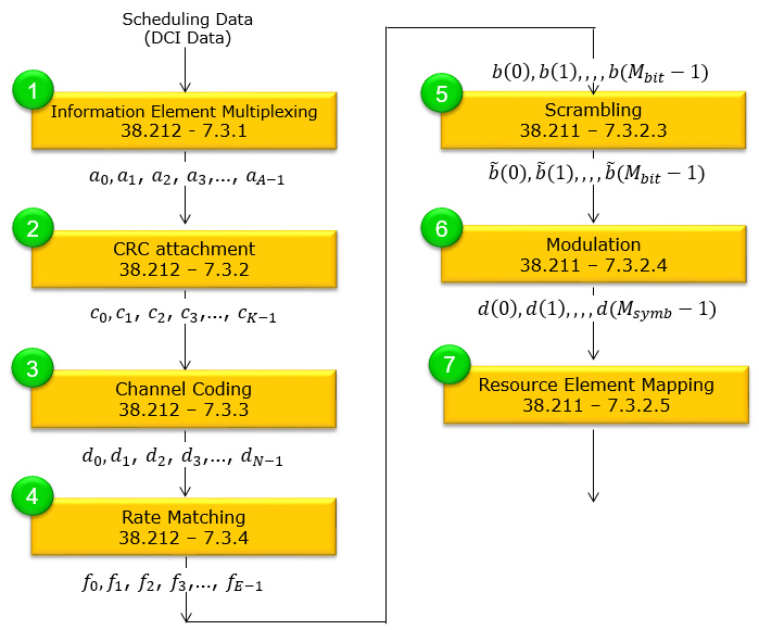
Figure 1. The seven steps, and the clause that defines each one. Steps 1 to 4 are in 38.212 and steps 5 to 7 are in 38.211, and the bit sequence changes its name where the two specifications meet.
Steps 1 to 4 are 38.212 : Information Element Multiplexing in clause 7.3.1, CRC attachment in 7.3.2, Channel Coding in 7.3.3 and Rate Matching in 7.3.4.Steps 5 to 7 are 38.211 : Scrambling in clause 7.3.2.3, Modulation in 7.3.2.4 and Resource Element Mapping in 7.3.2.5.The bit sequence is named between the blocks : a leaves step 1, c leaves step 2, d leaves step 3 and f leaves step 4.The name changes at the boundary : the f sequence arrives at scrambling as b(0) to b(Mbit - 1), and those are the same bits written under two conventions.
That last point is worth a moment, because the two specifications look inconsistent at the seam. 38.212 writes a bit index as a subscript, and its output stops at fE-1. 38.211 writes the index in parentheses, and its input starts at b(0). Nothing is done to the bits in between. The specification changes, and the notation changes with it.
The split also explains the shape of the process. Everything up to rate matching is bit processing, and it belongs to channel coding. Everything after it is physical channel processing, and those same three steps appear for every physical channel in NR.
(1) Information Element Multiplexing
This is a process of generating a bit string of DCI carrying various control and scheduling information. Refer to DCI page to see the details of the contents. The name is easy to misread. Nothing is multiplexed between UEs or between channels at this step. The fields of one DCI format are laid out in the order that format defines, and the result is a single bit string.
If the size of DCI is less than 12 bit, it will be zero padded until it become 12 bits (Ref [1]).
The same rule is in 38.212. When the number of information bits in a DCI format is less than 12, zeros are appended until the payload size equals 12.
The upper end of the range is the harder constraint, because the length is not free. Every distinct payload length a UE has to test is a separate blind decode, so the number of lengths is capped. 38.212 clause 7.3.1.0 runs a size alignment procedure, and it stops when two conditions hold. A UE monitors no more than four different DCI sizes for a cell, and no more than three of those are scrambled by C-RNTI.
Padding and truncation are how that budget is met. When DCI format 0_0 comes out shorter than DCI format 1_0 for the same cell, zeros are appended until the two lengths match. When it comes out longer, the frequency domain resource assignment field is shortened from its most significant bits instead. The two formats then share one size, and they cost one blind decode between them rather than two.
That is the reason a DCI format is padded at all. The padding is not there to fill a convenient boundary. It exists so that two formats can be tested by a single decode attempt.
(2) CRC Attachment
The CRC on a PDCCH does more than detect errors. A DCI carries no explicit UE identifier anywhere in its payload, so the CRC is also how a UE knows the message is meant for it. Masking the CRC with an RNTI is the whole of the addressing, and detection and addressing therefore share the same 24 bits.
That is why this section has three parts rather than one. The CRC is attached, the last 16 bits of it are masked with an RNTI, and the result is interleaved so the CRC bits are spread through the payload.
Figure 2 illustrates the CRC Attachment process for the 5G PDCCH (Physical Downlink Control Channel). As you see here, 24 bits CRC is appeded to DCI data.
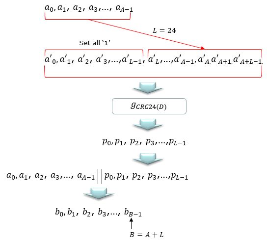
Figure 2. The CRC is computed over a padded sequence rather than over the DCI alone. The L ones sit in front of the payload and are never transmitted, so only a and p leave this step.
Initially, DCI (Downlink Control Information) data is presented as a sequence of bits a0, a1, a2, ..., aA-1. A 24-bit CRC is appended to this DCI data.
To prepare for CRC attachment, a sequence is extended by setting the L bits that precede the DCI data to '1', with L equal to 24. The result is an extended sequence a'0, a'1, a'2, ..., a'L-1, a'L, ..., a'A+L-1. This sequence is processed using a generator polynomial GCRC24(D), producing a CRC of bits p0, p1, p2, ..., pL-1.
The DCI data and CRC are then concatenated, forming a complete sequence a0, a1, a2, ..., aA-1 | p0, p1, p2, ..., pL-1, which is denoted by b0, b1, b2, ..., bB-1. The total length of the sequence after CRC attachment is B = A + L.
This CRC attachment process is a crucial step in ensuring the integrity of the control information as it allows the receiver to detect any errors that may have occurred during the transmission.
One detail of the padding is easy to miss. The L ones are prepended for the CRC calculation only, and they are never transmitted. The sequence leaving this step is therefore exactly A + L bits long, which Figure 2 marks as B = A + L.
Figure 3 shows what happens next. After CRC Attach, the last 16 bit is masked with a specific RNTI. Using this RNTI, UE figures out which UE the DCI is for and what is the usage of the DCI.
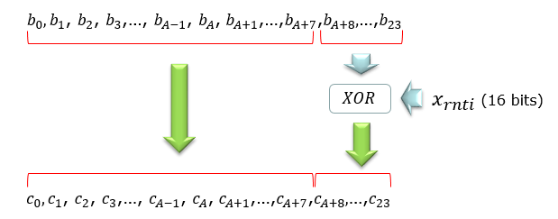
Figure 3. Only the last 16 of the 24 CRC bits are masked. The 8 bits before them pass through untouched, and that is what still detects errors after the RNTI has been applied.
After the CRC is appended to the DCI data, resulting in the sequence b0, b1, b2, ..., bA-1, bA, ..., b23, the last 16 bits are masked with a specific RNTI (Radio Network Temporary Identifier).
This masking is performed by XORing the last 16 bits of the sequence with the 16-bit RNTI, denoted as xRNTI. The RNTI is a unique identifier that enables the User Equipment (UE) to determine which DCI is intended for it and understand the usage of the DCI.
The output of this process is a new sequence c0, c1, c2, ..., cA-1, cA,...,cA+7,cA+B, ..., c23, where the last 16 bits have been modified by the RNTI masking. This step is crucial for directing the DCI to the correct UE and for protecting the information's integrity.
After RNTI masking, the data is interleaved so that CRC bits are distributed among information bits. This interleaver supports a max input size of 164 bits meaning that DCI without CRC can be max 140 bits.(Ref [1])
(3) Channel Coding
Figure 4 shows the Channel Coding step, which is part of the PDCCH channel coding processing. Polar coding is the difference from LTE, where PDCCH used tail biting convolutional coding. The change matters at these block lengths, because a DCI payload is short and the decoder has to work at a very low code rate. The four parameters drawn beside the block are the values 38.212 clause 7.3.3 fixes for DCI, and they do not vary with the DCI format.
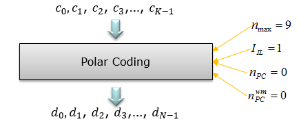
Figure 4. The four values beside the block are what 38.212 clause 7.3.3 fixes for DCI. An IIL of 1 turns the input bit interleaver on, and both parity check counts are 0.
In this step, the sequence c0, c1, c2, ..., cK-1 undergoes Polar Coding, a method known for its efficiency in error correction capabilities.
The Polar Coding process is characterized by four parameters. The first is nmax. It represents the maximum number of reliable sequence indices, and it is set to 9. The second is IIL, the input bit interleaving flag. A value of 1 means the interleaving of 38.212 clause 5.3.1.1 is applied. The third is npc, the number of parity check bits, and it is 0 in this case. The fourth is npcwm, another parity check parameter, also set to 0 here.
After Polar Coding, the data sequence is transformed into d0, d1, d2, ..., dN-1, which is ready for subsequent transmission steps. This coded sequence is more resistant to errors during transmission over the communication channel.
(4) Rate Matching
Figure 5 illustrates the Rate Matching step in PDCCH channel processing, which is essential for adapting the coded data to the correct size for transmission.
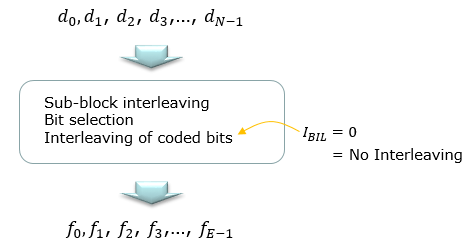
Figure 5. Three operations are drawn and only two of them run. IBIL is 0 for PDCCH, so the coded bit interleaving of 38.212 clause 5.4.1.3 is skipped.
Starting with the coded data sequence d0, d1, d2, ..., dN-1, the process involves sub-block interleaving and bit selection. Interleaving of coded bits is indicated, but with IBIL set to 0, this implies that there is no interleaving applied to the data.
Following this, the data sequence is adjusted to match the transmission rate, resulting in a new sequence f0, f1, f2, ..., fE-1. This rate matching process ensures that the data fits into the allocated transmission resources and is correctly received and decoded by the User Equipment.
(5) Scrambling
Figure 6 illustrates the scrambling process, which is essential for ensuring data integrity and security. The word security there is worth reading carefully, because scrambling is not encryption. Its purpose is to make a neighbouring cell's PDCCH look like noise rather than like a valid codeword. That is why the initialisation depends on an identity rather than on a key.
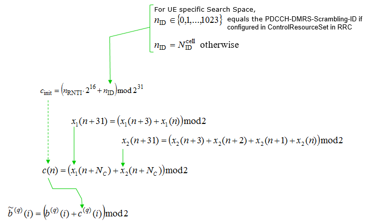
Figure 6. The initialisation carries an identity and an RNTI, and which values those take depends on the search space. That dependency is why the sequence differs between cells and between UEs.
The scrambling process uses an initialization sequence cinit that is derived from the RNTI (Radio Network Temporary Identifier) and an identifier nID.
For UE specific search spaces, nID is set to a value defined by the PDCCH-DMRS-Scrambling-ID if configured in ControlResourceSet in the RRC (Radio Resource Control) layer, which can range from 0 to 1023. Otherwise, nID equals NIDcell, the physical cell ID.
The initialization sequence is calculated as cinit = (RNTI * 216 + nID) mod 231. Two sequences x1(n) and x2(n) are generated and used to produce the scrambling sequence c(n) through a defined polynomial relationship.
Finally, the data bits b(i) are scrambled with c(n) to produce the scrambled bits b~(i) = (b(i) + c(i)) mod 2. This scrambled sequence is more resistant to interference and unauthorized interception, enhancing the overall security and reliability of the communication.
Two details in 38.211 clause 7.3.2.3 are easy to miss, and both change the value of cinit.
The first is the RNTI term. It carries the C-RNTI only for a PDCCH in a UE specific search space, and only when pdcch-DMRS-ScramblingID is configured. Otherwise the term is 0. A PDCCH in a common search space is therefore scrambled from the cell identity alone, and every UE in the cell descrambles it the same way.
The second is that the UE specific case is no longer the only one that uses the configured identity. That also covers a PDCCH with its CRC scrambled by G-RNTI, G-CS-RNTI, MCCH-RNTI or Multicast-MCCH-RNTI in a common search space. Such a PDCCH takes nID from pdcch-DMRS-ScramblingID too, when the parameter is configured in a common MBS frequency resource.
(6) Modulation
Figure 7 depicts the modulation process for PDCCH. PDCCH has one modulation order and no adaptation at all. QPSK is the only scheme 38.211 clause 7.3.2.4 allows, so a control channel never trades robustness for rate the way PDSCH does. Link adaptation happens through the aggregation level instead.
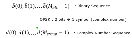
Figure 7. QPSK maps two bits to one symbol, so the symbol count is exactly half the bit count. This is the only modulation PDCCH uses.
The process starts with a binary sequence represented as b~(0), b~(1), ..., b~(Mbit - 1). This sequence undergoes Quadrature Phase Shift Keying (QPSK) modulation, which is a method that maps every two bits of the binary sequence to one symbol, represented as a complex number. Thus, two binary bits are converted into a single QPSK symbol.
After modulation, the sequence of binary bits is transformed into a sequence of complex numbers, d(0), d(1), ..., d(Msymb - 1), where each symbol in this new sequence corresponds to a pair of binary bits from the original sequence. The result of this modulation is a complex number sequence suitable for transmission over the radio frequency spectrum.
(7) Resource Element Mapping
This is putting the ecoded and modulated PDCCH bits into each resource elements in NR resource grid. Two constraints shape that mapping, and both are in 38.211 clause 7.3.2.5. The resource elements carrying the associated PDCCH DMRS are excluded, so the data and its reference signal share a CORESET without overlapping. The order is fixed as well, and it runs frequency first.
The gNB should assume a block of complex-valued symbols d(0), ..., d(Msymb - 1) is to be scaled by a factor βPDCCH and then mapped to resource elements (k, l)p, u that are designated for the monitored PDCCH and not used for the associated PDCCH DMRS. The mapping order should follow an increasing sequence of first k, then l. The specified antenna port for this operation is p = 2000.
The process can be described in step by step as follows:
- The gNB prepares a block of complex-valued symbols represented as d(0), d(1), ..., d(Msymb - 1).
- Each symbol in the block is scaled by a predefined factor, βPDCCH.
- The scaled symbols are mapped onto resource elements, denoted as (k, l)p,u, where k is the subcarrier index and l is the OFDM symbol index within a slot.
- This mapping follows an ascending order, first by subcarrier index k, then by OFDM symbol index l.
- It is ensured that the resource elements used for PDCCH do not overlap with those allocated for the associated PDCCH DMRS.
- The antenna port used for this operation is specified as p = 2000.
Through these steps, the gNB systematically assigns the PDCCH symbols to the appropriate resources on the frequency-time grid for effective transmission.
RRC Parameters
PDCCH-Config is the UE specific half of the PDCCH configuration, and PDCCH-ConfigCommon is the other half. The common part is broadcast, and it sets up the CORESET and the search spaces a UE needs before it has anything dedicated. This section covers the dedicated part, and the listing below is its current form.
Following is based on
PDCCH-Config ::=                    SEQUENCE {
    controlResourceSetToAddModList      SEQUENCE(SIZE (1..3)) OF ControlResourceSet                      OPTIONAL,   -- Need N
    controlResourceSetToReleaseList     SEQUENCE(SIZE (1..3)) OF ControlResourceSetId                    OPTIONAL,   -- Need N
    searchSpacesToAddModList            SEQUENCE(SIZE (1..10)) OF SearchSpace                            OPTIONAL,   -- Need N
    searchSpacesToReleaseList           SEQUENCE(SIZE (1..10)) OF SearchSpaceId                          OPTIONAL,   -- Need N
    downlinkPreemption                  SetupRelease { DownlinkPreemption }                              OPTIONAL,   -- Need M
    tpc-PUSCH                           SetupRelease { PUSCH-TPC-CommandConfig }                         OPTIONAL,   -- Need M
    tpc-PUCCH                           SetupRelease { PUCCH-TPC-CommandConfig }                         OPTIONAL,   -- Need M
    tpc-SRS                             SetupRelease { SRS-TPC-CommandConfig}                            OPTIONAL,   -- Need M
    ...,
    [[
    controlResourceSetToAddModListSizeExt-v1610 SEQUENCE (SIZE (1..2)) OF ControlResourceSet             OPTIONAL,   -- Need N
    controlResourceSetToReleaseListSizeExt-r16 SEQUENCE (SIZE (1..5)) OF ControlResourceSetId-r16        OPTIONAL,   -- Need N
    searchSpacesToAddModListExt-r16     SEQUENCE(SIZE (1..10)) OF SearchSpaceExt-r16                     OPTIONAL,   -- Need N
    uplinkCancellation-r16              SetupRelease { UplinkCancellation-r16 }                          OPTIONAL,   -- Need M
    monitoringCapabilityConfig-r16      ENUMERATED { r15monitoringcapability,r16monitoringcapability }   OPTIONAL,   -- Need M
    searchSpaceSwitchConfig-r16         SearchSpaceSwitchConfig-r16                                      OPTIONAL    -- Need R
    ]],
    [[
    searchSpacesToAddModListExt-v1700   SEQUENCE(SIZE (1..10)) OF SearchSpaceExt-v1700                   OPTIONAL,   -- Need N
    monitoringCapabilityConfig-v1710    ENUMERATED { r17monitoringcapability }                           OPTIONAL,   -- Need M
    searchSpaceSwitchConfig-r17         SearchSpaceSwitchConfig-r17                                      OPTIONAL,   -- Need R
    pdcch-SkippingDurationList-r17      SEQUENCE(SIZE (1..3)) OF SCS-SpecificDuration-r17                OPTIONAL    -- Need R
    ]],
    [[
    pdcch-MonitoringResumptionAfterNack-r18 ENUMERATED {true}                                            OPTIONAL,   -- Need R
    searchSpacesToAddModListExt-v1800   SEQUENCE(SIZE (1..10)) OF SearchSpaceExt-v1800                   OPTIONAL    -- Need N
    ]],
    [[
    searchSpaceSwitchConfig-r19         SearchSpaceSwitchConfig-r19                                      OPTIONAL,   -- Need R
    searchSpacesToAddModListExt-v1900   SEQUENCE(SIZE (1..10)) OF SearchSpaceExt-v1900                   OPTIONAL    -- Need N
    ]]
}

SearchSpaceSwitchConfig-r16 ::=     SEQUENCE {
    cellGroupsForSwitchList-r16         SEQUENCE(SIZE (1..4)) OF CellGroupForSwitch-r16                  OPTIONAL,   -- Need R
    searchSpaceSwitchDelay-r16          INTEGER (10..52)                                                 OPTIONAL    -- Need R
}

SearchSpaceSwitchConfig-r17 ::=     SEQUENCE {
    searchSpaceSwitchTimer-r17          SCS-SpecificDuration-r17                                         OPTIONAL,   -- Need R
    searchSpaceSwitchDelay-r17          INTEGER (10..52)                                                 OPTIONAL    -- Need R
}

SearchSpaceSwitchConfig-r19 ::=     SEQUENCE {
    sr-TriggeredSearchSpaceSwitchGroupId-r19 INTEGER (0.. maxNrofSearchSpaceGroups-1-r17)                OPTIONAL    -- Need R
}

CellGroupForSwitch-r16 ::=          SEQUENCE(SIZE (1..16)) OF ServCellIndex

SCS-SpecificDuration-r17   ::=      INTEGER (1..166)
Four of the fields are lists, and those carry the real configuration. Up to three CORESETs go in controlResourceSetToAddModList, and up to ten search spaces go in searchSpacesToAddModList. A search space points at a CORESET, so the two lists together decide where the UE looks and how often it looks there.
The Release 16 group raised those limits rather than replacing them. Two more CORESETs come from controlResourceSetToAddModListSizeExt-v1610, so a UE can hold five in total, and controlResourceSetToReleaseListSizeExt-r16 releases from the extended set.
Three fields in the later groups exist to make the UE decode less often. They are worth knowing even on a page that is not about power saving, because they change how often the process on this page runs at all.
monitoringCapabilityConfig-r16 selects which limit on blind decodes and non-overlapping CCEs applies. 38.213 clause 10.1 counts that limit per slot for r15monitoringcapability, per span for r16monitoringcapability, and per group of slots for r17monitoringcapability.
searchSpaceSwitchConfig-r16, together with its Release 17 and Release 19 forms, moves the UE between search space set groups. Group index 0 is the group the UE resets to. The switch applies across a group of serving cells when cellGroupsForSwitchList-r16 is provided. The delay itself, searchSpaceSwitchDelay, is a number of symbols taken from 38.213 Table 10.4-1.
pdcch-SkippingDurationList-r17 gives a set of durations for a Type3-PDCCH common search space set or a UE specific search space set. A DCI can then tell the UE to stop monitoring for one of those durations, and SCS-SpecificDuration-r17 states it as an integer from 1 to 166.
One further field belongs to a different problem. The field uplinkCancellation-r16 configures the UE to receive DCI format 2_4. That DCI tells the UE to stop an uplink transmission already in progress, so a URLLC transmission can take the resources.
The fields that are not lists have something in common. Between them, downlinkPreemption, tpc-PUSCH, tpc-PUCCH, tpc-SRS and uplinkCancellation-r16 all configure the UE to receive a group common DCI rather than a scheduling grant. 38.212 Table 7.3.1-1 names what each one carries. Format 2_1 marks resources where no transmission is intended for the UE. Format 2_2 carries TPC commands for PUCCH and PUSCH. Format 2_3 carries a group of TPC commands for SRS. Format 2_4 marks resources where the UE cancels an uplink transmission. Each of those formats has its own RNTI and its own search space, so these fields add to what the UE monitors rather than to what it is scheduled.
Two halves, one channel : PDCCH-ConfigCommon is broadcast and PDCCH-Config is dedicated, and a UE uses both at the same time.The lists are the configuration : three CORESETs and ten search spaces per bandwidth part, with two more CORESETs available from the Release 16 group.The later groups mostly reduce monitoring : monitoring capability, search space set switching and PDCCH skipping all cut how often the UE decodes.An extension group is not optional reading : four have been added since Release 15, so a listing that stops at the first ellipsis is missing most of the current IE.
Reference
[1] Understanding the Heart of the 5G Air Interface: An Overview of Physical Downlink Control Channel for 5G New Radio (NR)
- by Kazuki Takeda, Huilin Xu, Taehyoung Kim, Karol Schober∧, and Xingqin Lin#
Qualcomm Inc., Samsung Electronics,∧Nokia, #Ericsson Inc.
[2] TS 38.211 - Physical channels and modulation (clauses 7.3.2.3 to 7.3.2.5)
[3] TS 38.212 - Multiplexing and channel coding (clauses 7.3.1 to 7.3.4, 5.3.1 and 5.4.1)
[4] TS 38.331 - Radio Resource Control (RRC) protocol specification (PDCCH-Config)
[5] TS 38.213 - Physical layer procedures for control (clauses 10.1 and 10.4)