Reference Signals(RS) are crucial components in both LTE and NR wireless communication systems. In LTE, various types of Reference Signals are utilized, and these signals serve similar fundamental roles in NR. However, despite their similarities, there are notable differences between the Reference Signals used in LTE and those in NR. These differences are significant and can be described in detail as follows:
In NR, there is no CRS (Cell Specific Reference Signal) . The CRS in LTE is used for various purposes, such as channel estimation, cell identification, and synchronization across the cell. Its absence in NR reflects a shift in design philosophy, as NR relies on other mechanisms and signals to achieve similar functionalities, optimizing for the demands of 5G networks, such as higher data rates, lower latency, and improved efficiency.In NR, there is a new reference signals Phase Tracking Reference Signal, PBCH Reference Signal, Time/Frequency Tracking Reference Signal and DMRS (Demodulation Reference Signal) for various channels(e.g, PDCCH, PDSCH etc) are some examples of the new reference signals
Type of Reference Signal
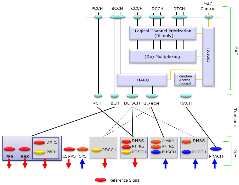
There are various types of Reference Signals in NR (New Radio), and the types of reference signals along with their roles can be summarized in a diagram, as shown below. The diagram illustrates the structure and interaction of reference signals within the NR protocol stack, spanning across different layers and channels.
At the physical layer (PHY), the diagram highlights several key reference signals and their association with specific physical channels. The reference signals, marked in red, are integral to the operation of NR and are used for tasks such as channel estimation, synchronization, and phase tracking.
Overall, the diagram effectively maps out the various types of reference signals in NR—such as DMRS, PT-RS, PBCH Reference Signal, CSI-RS, SRS, and others—and their roles in supporting the physical channels and ensuring robust, high-performance communication in 5G networks.
List of all NR reference signal can be summarized as follows. The details of each reference signal will be posted as separate page.
|
Reference Signal |
Functionality |
3GPP Reference |
|
Required for Sync Detection |
38.211-7.4.3.1, 38.213-4.1 |
|
|
CSI aquisition, Beam Management |
38.211-7.4.1.5 |
|
|
Required for PDSCH Demodulation |
38.211-7.4.1.1 |
|
|
Required for PUSCH Demodulation |
38.211-6.4.1.1 |
|
|
PDCCH DMRS |
Required for PDCCH Demodulation |
38.211-7.4.1.3 |
|
PUCCH DMRS |
Required for PUCCH Demodulation |
38.211-6.4.1.3 |
|
Sounding Reference Signal |
38.211-6.4.1.4 |
|
|
Required for PBCH Demodulation |
38.211-7.4.1.4 |
|
|
Used for Phase Tracking for PDSCH |
38.211-7.4.1.2 |
|
|
Used for Time Tracking |
38.211-7.4.1.6 |
How to Detect Reference Signal
Based on this definition, NR Cell Search procedure can be broken down to several steps as follows : (Even though it may seem simple process, this is very complicated process if you go in detail. First, try to understand overall procedure as described below and then follow through the linked pages for further details for each of the steps).
1) UE tunes to a specific frequency (How UE select this specific freuqency to tune to ?)
2) UE tries to detect SSB and decode PSS, SSS. If UE fails at this step, it goes to step i) and passes at this step, go to next
3) Once UE successfully detect PSS/SSS, it can construct the resource grid for SSB
4) From the resource grid, it can decode PBCH DMRS.
5) From SSB resource grid with the help of PBCH DMRS, it can decode PBCH / MIB
6) Based on MIB.pdcch-ConfigSIB1, find the location of CORESET0 (CORESET for PDCCH/DCI for SIB1 transmission) and SearchSpace information. This CORESET0 finding is done by predefined parameters as described here.
7) Blind decode DCI 1_0 in the SearchSpace.
8) Based on the contents of the DCI 1_0. (
9) Detect and decode PDSCH carrying SIB1.
10) decode SIB1 and other SIBs (if SIB1 carries information on other SIBs).
11) Once the SIB1 is decoded, UE can figure out various other fundamental information like channel bandwidth, center frequency of the channel etc as shown here.
12) Based on the information obtained from SIB1 (i.e, Channel bandwidth, subcarrier spacing), UE can construct the resource grid for the entire bandwidth.
13) Proceed to RACH procedure
14) If RACH procedure is successfully done, UE can receive and decode RRC Setup.
15) Based on the information from RRC Setup, UE can figure out exact resource element for DMRS for other channels (e.g, PDCCH, PDSCH, PUSCH etc) and other signals (e.g, CSI-RS, TRS, SRS etc)
Reference
[1]