|
SRS in Detail
SRS stands for Sounding Reference Signal. High level concept of NR SRS is same as in LTE SRS and some of lower level parameter are very similar to LTE SRS lower layer parameter. I would suggest you to go through LTE SRS first if you are new to this concept and then read this page since I would not explain on those basic concepts that are explained in LTE SRS.
Simply put, SRS is a kind of reference signal for Uplink (i.e, transmitted by UE) so that gNB can perform channel quality estimation for uplink. gNB can perform UL channel estimation from PUSCH DMRS, but PUSCH DMRS is transmitted only when PUSCH is scheduled and only with the bandwidth in which PUSCH is scheduled. On the contrary, SRS can be transmitted independantly of PUSCH scheduling and PUSCH bandwidth(number of PUSCH RB).
In short, the role of SRS is similar to CSI RS. CSI-RS is a reference signal for downlink channel quality estimation independent of PDSCH DMRS and SRS is a reference signal for uplink channel quality estimation independent of PUSCH DMRS
SRS plays more important role in NR because TDD is dominant mode of deployment. In TDD, gNB can utilize the channel estimation result from SRS not only for UL scheduling but also for DL scheduling as well based on channel reciprocity in TDD.
- How SRS works
- Parameters defining SRS resources within a slot.
- SRS Bandwidth Configuration
- UE Capabilities
- Antenna Switching
- RRC Parameters
- Get the Test Procedure and Log / Amarisoft TechAcademy
How SRS works ?
In short, the way SRS works can be illustrated as follows.
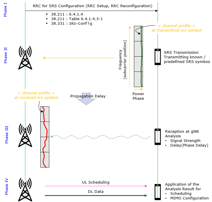
This is the phase where gNB determines about SRS configuration (e.g, SRS physical resources, usage, report period timing etc) and notifies the configuration to UE via RRC messages (e.g, RRCSetup, RRCReconfiguration).
In this phase, the UE transmits the SRS, which is a predefined signal with known characteristics, at a specific time and frequency. The SRS configuration is provided to the UE by the gNB, and it may vary depending on the cell's conditions and traffic requirements. The UE sends the SRS periodically or aperiodically, as instructed by the gNB, on the uplink (UL) channel.
Upon receiving the SRS from the UE, the gNB measures and analyzes the received signal. It estimates the channel state information (CSI) by comparing the received SRS with the known reference signal. The gNB evaluates various parameters, such as the path loss, propagation delay(phase delay), and received signal strength, to understand the current radio environment and channel conditions between the gNB and the UE.
Once the gNB has estimated the channel state based on the SRS, it uses this information to optimize its resource allocation and scheduling decisions. This can involve adjusting transmission parameters (such as modulation and coding schemes) or selecting the most appropriate MIMO settings to enhance the overall system capacity and improve the user experience. By leveraging the SRS, the gNB can adapt to the dynamic nature of the radio environment and provide more efficient and reliable communication services.
Parameters defining SRS resources within a slot.
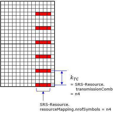
SRS resource mean the location of SRS in time and frequency domain in the resource grid. Following is the illustration for SRS Resource allocation based on 38.211-6.4.1.4.
NOTE : For more detailed example of SRS resource element allocation, refer to this page with Matlab 5G Toolbox.
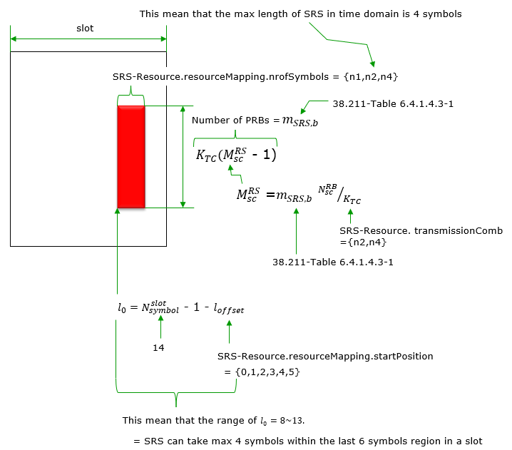
Followings are breakdown and description for the digram shown above. It is a detailed explanation of how the allocation works in the time and frequency domains.
- The maximum duration of SRS in the time domain is 4 symbols within a slot.
- Each slot contains 14 OFDM symbols.
- SRS symbols are allocated in the last 6 symbols of the slot (range: l0 = 8 to 13).
- The starting position of SRS symbols is calculated as:
- Nslot_symbol: Total symbols in a slot (14 symbols).
- loffset: Offset value, defined in SRS-Resource.resourceMapping.startPosition. Possible values: {0, 1, 2, 3, 4, 5}.
l0 = Nslot_symbol - 1 - loffset
- The number of PRBs allocated for SRS transmission is denoted as mSRS,b.
- It is calculated using the formula:
- NRBSC: Number of subcarriers per PRB (12 in 5G).
- KTC: Transmission comb parameter, defined in SRS-Resource.transmissionComb (n2, n4).
MRSSC = mSRS,b � NRBSC / KTC
- Details are specified in 38.211 Table 6.4.1.4.3-1, including:
- Possible values for the number of OFDM symbols: {n1, n2, n4}.
- Configurations for KTC and MRSSC.
Here goes the detailed algorithm and parameters of SRS RE mapping based on 38.211-6.4.1.4.3
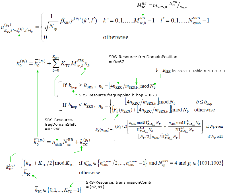
NOTE : from the equation for k(pi), you would notice that the multiple SRS port (i.e, 1001 ~ 1003} is interleaving in frequency domain within the same OFDM symbol.
Here's an explanation of the components:
The following describes the algorithm and parameters for Sounding Reference Signal (SRS) Resource Element (RE) mapping in 5G NR.
- The scaling factor for each RE is defined as:
α(p,i)(k', l') =(1/√Nap) βSRS(pi)(k', l') for k' = 0, 1, ..., MRSSC - 1 and l' = 0, 1, ..., NSRSsymb - 1
- 0 otherwise.
- The starting subcarrier is calculated as:
k0(pi) = k�0pi + Σb=0BSRS - 1 KTC MRSSC,b nb
- The hopping pattern is defined as:
nb =
- Case 1 : ⌊4nRRC / mSRS,b⌋ mod Nb if b ≥ Bhop
- Case 2 : Fb(nSRS) + ⌊4nRRC / mSRS,b⌋ mod Nb if b < Bhop
- Comb-based subcarrier mapping is:
k�(pi)TC = (k�TC + KTC / 2) mod KTC
- KTC: Transmission comb parameter (n2, n4).
- Ensures interleaving in frequency domain.
- Subcarriers for SRS blocks are calculated as:
MRSSC = mSRS,b � (NRBSC / KTC)
- mSRS,b: Number of PRBs.
- NRBSC: Subcarriers per PRB (12 in 5G).
Followings are some of the examples showing the key parameters of SRS resource allocation.
|
|
 |
|
|
 |

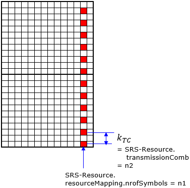
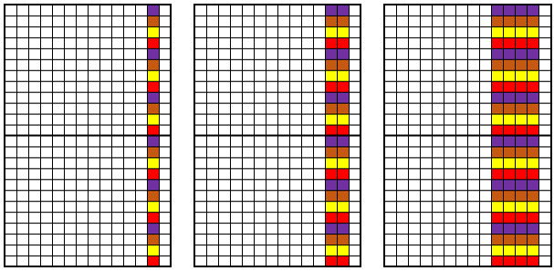
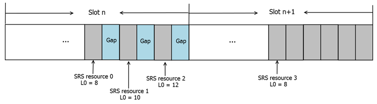
Since SRS resources are positioned in a certain interval in frequency domain as shown above, we can interleave (multiplex) multiple SRS along the frequency domain accupying the same OFDM symbols as shown below.
In case of comb2 configuration, you can multiplex two SRS signal as shown below.
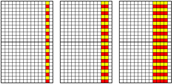
In case of comb4 configuration, you can multiplex maximum 4 SRS signals as shown below.
SRS Bandwidth Configuration
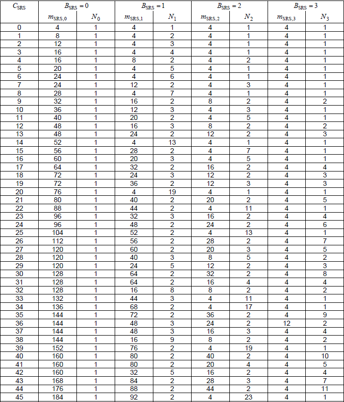
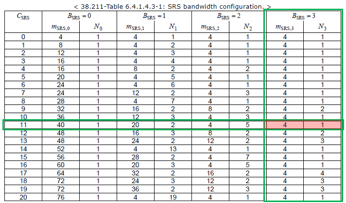
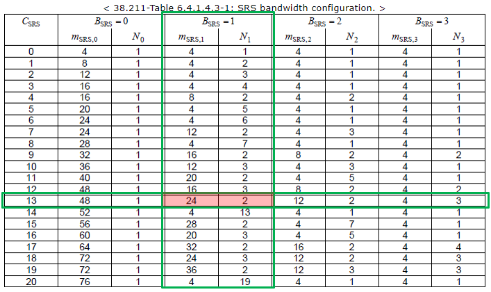
Some of important factors defining the location and bandwith of SRS are defined by 38.211-Table 6.4.1.4.3-1. A couple of RRC parameter determines which row of the table is used for a specific SRS Resource set as indicated below.
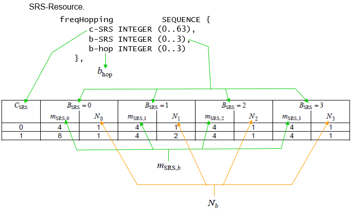
< 38.211-Table 6.4.1.4.3-1: SRS bandwidth configuration. >

UE Capabilities
SRS related UE capability is pretty complicated topic and I still don't have complete understandings on this. I am just adding small items as I learn more on this issue.
I think the most fundamental UE capability about SRS is following (38.214-621)
The UE capability of this statement is described in supportedSRS-Resources in 38.306.
An example of UE capability information from a commercial device is as follows : (The protocol log is captured by Amarisoft Callbox and a Commercial UE).
featureSetsUplink {
{
featureSetListPerUplinkCC {
1
},
supportedSRS-Resources {
maxNumberAperiodicSRS-PerBWP n16,
maxNumberAperiodicSRS-PerBWP-PerSlot 6,
maxNumberPeriodicSRS-PerBWP n16,
maxNumberPeriodicSRS-PerBWP-PerSlot 6,
maxNumberSemiPersistentSRS-PerBWP n2,
maxNumberSemiPersistentSRS-PerBWP-PerSlot 2,
maxNumberSRS-Ports-PerResource n1
}
},
{
featureSetListPerUplinkCC {
2
},
supportedSRS-Resources {
maxNumberAperiodicSRS-PerBWP n16,
maxNumberAperiodicSRS-PerBWP-PerSlot 6,
maxNumberPeriodicSRS-PerBWP n16,
maxNumberPeriodicSRS-PerBWP-PerSlot 6,
maxNumberSemiPersistentSRS-PerBWP n2,
maxNumberSemiPersistentSRS-PerBWP-PerSlot 2,
maxNumberSRS-Ports-PerResource n1
}
},
Followings are for UE Capability Information
FeatureSetUplink ::= SEQUENCE {
featureSetListPerUplinkCC SEQUENCE (SIZE (1.. maxNrofServingCells)) OF
FeatureSetUplinkPerCC-Id,
scalingFactor ENUMERATED {f0p4, f0p75, f0p8} OPTIONAL,
crossCarrierScheduling-OtherSCS ENUMERATED {supported} OPTIONAL,
intraBandFreqSeparationUL FreqSeparationClass OPTIONAL,
searchSpaceSharingCA-UL ENUMERATED {supported} OPTIONAL,
supportedSRS-Resources SRS-Resources OPTIONAL,
twoPUCCH-Group ENUMERATED {supported} OPTIONAL,
dynamicSwitchSUL ENUMERATED {supported} OPTIONAL,
simultaneousTxSUL-NonSUL-v1530 ENUMERATED {supported} OPTIONAL,
pusch-DifferentTB-PerSlot SEQUENCE {
scs-15kHz ENUMERATED {upto2, upto4, upto7} OPTIONAL,
scs-30kHz ENUMERATED {upto2, upto4, upto7} OPTIONAL,
scs-60kHz ENUMERATED {upto2, upto4, upto7} OPTIONAL,
scs-120kHz ENUMERATED {upto2, upto4, upto7} OPTIONAL
} OPTIONAL,
csi-ReportFramework CSI-ReportFramework OPTIONAL
}
SRS-TxSwitch ::= SEQUENCE {
supportedSRS-TxPortSwitch ENUMERATED {t1r2, t1r4, t2r4, t1r4-t2r4, t1r1, t2r2,
t4r4, notSupported},
txSwitchImpactToRx ENUMERATED {true} OPTIONAL
}
Example 01 > UE Capability Information - t1r2
supportedBandCombinationList-v1540 {
{
bandList-v1540 {
{
srs-TxSwitch {
supportedSRS-TxPortSwitch t1r2
}
}
},
ca-ParametersNR-v1540 {
csi-RS-IM-ReceptionForFeedbackPerBandComb {
maxNumberSimultaneousNZP-CSI-RS-ActBWP-AllCC 8,
totalNumberPortsSimultaneousNZP-CSI-RS-ActBWP-AllCC 64
},
simultaneousCSI-ReportsAllCC 8
}
},
....
}
Antenna Switching
Following RRC parameter is to configure UE to do SRS antenna switching
SRS-ResourceSet.usage = antennaSwitching
UE performs antenna switching in various way depending on RRC parameter setting in SRS-ResourceSet as described in 38.214 6.2.1.2. Which of the following case should be applied ? It depends on UE capability on supportedSRS-TxPortSwitch which can be 1T2R or 1T4R or 2T4R or T=R
-
Number of SRS ResourceSet =
up to two -
Each ResourceSet has
two SRS Resources transmitting at different symbols -
Each SRS Resource in a ResourceSet consists of
single SRS port and the SRS port of the second resource in the set is associated with a different UE antenna port than the SRS port of the first resource in the same set - SRS-ResourceSet.resourceType : configured (aperiodic / semi-persistent / periodic)
-
Number of SRS ResourceSet =
up to two -
Each ResourceSet has
two SRS Resources transmitting at different symbols -
Each SRS Resource in a ResourceSet consists of
two SRS ports and the SRS port pair of the second resource in the set is associated with a different UE antenna port pair than the SRS port of the first resource in the same - SRS-ResourceSet.resourceType : configured (aperiodic / semi-persistent / periodic)
-
Number of SRS ResourceSet =
zero or one -
Each ResourceSet has
four SRS Resources transmitting at different symbols -
Each SRS Resource in a ResourceSet consists of
single SRS ports and the SRS port of each resource is associated with a different UE antenna port - SRS-ResourceSet.resourceType : configured (periodic / semi-persistent)
- Number of SRS ResourceSet =
zero or two - Each ResourceSet has
four SRS Resources transmitting at different symbols of two different slot - SRS port of each SRS resource in given two sets is associated with a different UE antenna port
- The two sets are each configured with two SRS resources, or one set is configured with one SRS resource and the other set is configured with three SRS resources.
- SRS-ResourceSet.resourceType : configured (aperiodic)
-
Number of SRS ResourceSet =
upto two - number of SRS ports for each resource is equal to 1, 2, or 4.
Does this description make clear sense to you ? I think I have read this part in 38.214 almost 10 times, but still not clear to me. It is extremly difficult to read those short section of the specification without falling asleep :). Then I gave up reading 38.214 and start trying to find TDocs with some picture and tables. With following tables and pictures from TDocs, finally the description on 38.214 start making sense.
Followings are the figure from R1-1800116
< Illustration of 1T4R antenna switching for aperiodic SRS >
Examples : Antenna Switching
Examples in this section are the tables from R1-1800090 or other personal contributers. Here the terminology may sounda little confiusing. Let me try (at least try :) to clarify it.
- xTyR : x indicates the Number of Tx port and y indicates the number of Rx port. The Tx and Rx are from the point of UE. So Tx mean Uplink and Rx mean Downlink.
- UE antenna port : This indicates UE's Rx antenna port
- SRS port : This indicates the srs port. Each of srs port is mapped to separate resource grid.
- Number of SRS port is determined by the number of UL antenna.
NOTE : If you want to see the contents of full log for antenna switching with Amarisoft Log viewer, go to LogAnalysis section and click on 'Sample Log' in this tutorial of Amarisoft TechAcademy.
Example 01 > 1T2R
Typical example of this case is DL 2x2 MIMO (2R UE's from point of view) and UL SISO(1T UE's from point of view)
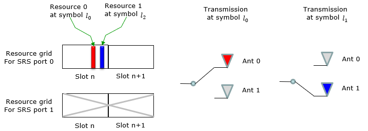
< Association between SRS ports and UE antenna ports for 1T2R >
|
SRS Ports |
UE Antenna Ports |
|
SRS port 0 of the first SRS resource |
UE antenna port 0 |
|
SRS port 0 of the second SRS resource |
UE antenna port 1 |
Example 02 > 2T4R
Typical example of this case is DL 4x4 MIMO (4R UE's from point of view) and UL 2x2 MIMO(2T UE's from point of view)
< Association between SRS ports and UE antenna ports for 2T4R >
|
SRS Ports |
UE Antenna Ports |
|
SRS port 0 of the first SRS resource |
UE antenna port 0 |
|
SRS port 1 of the first SRS resource |
UE antenna port 1 |
|
SRS port 0 of the second SRS resource |
UE antenna port 2 |
|
SRS port 1 of the second SRS resource |
UE antenna port 3 |

Example 03 > 1T4R
Typical example of this case is DL 4x4 MIMO (4R UE's from point of view) and UL SISO(1T UE's from point of view)
< Association between SRS ports and UE antenna ports for 1T4R >
|
SRS Ports |
UE Antenna Ports |
|
SRS port 0 of the first SRS resource |
UE antenna port 0 |
|
SRS port 0 of the second SRS resource |
UE antenna port 1 |
|
SRS port 0 of the third SRS resource |
UE antenna port 2 |
|
SRS port 0 of the fourth SRS resource |
UE antenna port 3 |

Example 04 > 1T4R
This example is shared by Sean. He is an ardent reader of sharetechnote and an experts on many subjects related to real deployment. He has been giving me a lot of insight on many topics and this example is one of them.
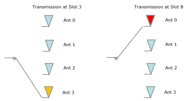
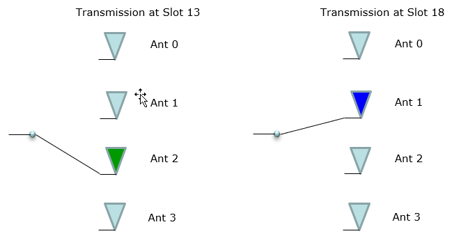
Following diagram shows SRS resource allocation at slot level. This would give you an idea on how SRS can be allocated with TDD UL-DL configuration. Of course, this is not the only possible way, you can come up with various other configuration depending on UE capability, Network capability/requirement.
In this example, you would notice that SRS is allocated in Flexible slot and the overall repetition cycle is 40 ms.
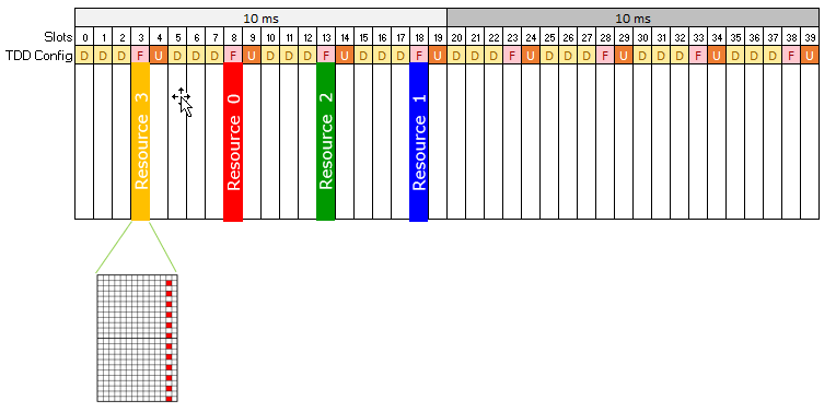
Following diagram shows the Antenna selection status for each slot where SRS is transmitted.
RRC Parameters
BWP-UplinkDedicated ::= SEQUENCE {
pucch-Config SetupRelease { PUCCH-Config } OPTIONAL, -- Need M
pusch-Config SetupRelease { PUSCH-Config } OPTIONAL, -- Need M
configuredGrantConfig SetupRelease { ConfiguredGrantConfig } OPTIONAL, -- Need M
srs-Config SetupRelease { SRS-Config } OPTIONAL, -- Need M
beamFailureRecoveryConfig SetupRelease { BeamFailureRecoveryConfig } OPTIONAL,
...
}
SRS-Config ::= SEQUENCE {
srs-ResourceSetToReleaseList SEQUENCE (SIZE(1..maxNrofSRS-ResourceSets))
OF SRS-ResourceSetId OPTIONAL, -- Need N
srs-ResourceSetToAddModList SEQUENCE (SIZE(1..maxNrofSRS-ResourceSets))
OF SRS-ResourceSet OPTIONAL, -- Need N
srs-ResourceToReleaseList SEQUENCE (SIZE(1..maxNrofSRS-Resources))
OF SRS-ResourceId OPTIONAL, -- Need N
srs-ResourceToAddModList SEQUENCE (SIZE(1..maxNrofSRS-Resources))
OF SRS-Resource OPTIONAL, -- Need N
tpc-Accumulation ENUMERATED {disabled} OPTIONAL, -- Need S
...
}
SRS-ResourceSet ::= SEQUENCE {
srs-ResourceSetId SRS-ResourceSetId,
srs-ResourceIdList SEQUENCE (SIZE(1..maxNrofSRS-ResourcesPerSet))
OF SRS-ResourceId OPTIONAL, -- Cond Setup
resourceType CHOICE {
aperiodic SEQUENCE {
aperiodicSRS-ResourceTrigger INTEGER (1..maxNrofSRS-TriggerStates-1),
csi-RS NZP-CSI-RS-ResourceId OPTIONAL, -- Cond NonCodebook
slotOffset INTEGER (1..32) OPTIONAL, -- Need S
...,
[[
aperiodicSRS-ResourceTriggerList-v1530 SEQUENCE (SIZE(1..maxNrofSRS-TriggerStates-2))
OF INTEGER (1..maxNrofSRS-TriggerStates-1)
]]
},
semi-persistent SEQUENCE {
associatedCSI-RS NZP-CSI-RS-ResourceId OPTIONAL,
...
},
periodic SEQUENCE {
associatedCSI-RS NZP-CSI-RS-ResourceId OPTIONAL,
...
}
},
usage ENUMERATED {beamManagement, codebook, nonCodebook, antennaSwitching},
alpha Alpha OPTIONAL, -- Need S
p0 INTEGER (-202..24) OPTIONAL, -- Cond Setup
pathlossReferenceRS CHOICE {
ssb-Index SSB-Index,
csi-RS-Index NZP-CSI-RS-ResourceId
} OPTIONAL, -- Need M
srs-PowerControlAdjustmentStates ENUMERATED { sameAsFci2, separateClosedLoop}
...
}
SRS-Resource ::= SEQUENCE {
srs-ResourceId SRS-ResourceId,
nrofSRS-Ports ENUMERATED {port1, ports2, ports4},
ptrs-PortIndex ENUMERATED {n0, n1 } OPTIONAL, -- Need R
transmissionComb CHOICE {
n2 SEQUENCE {
combOffset-n2 INTEGER (0..1),
cyclicShift-n2 INTEGER (0..7)
},
n4 SEQUENCE {
combOffset-n4 INTEGER (0..3),
cyclicShift-n4 INTEGER (0..11)
}
},
resourceMapping SEQUENCE {
startPosition INTEGER (0..5),
nrofSymbols ENUMERATED {n1, n2, n4},
repetitionFactor ENUMERATED {n1, n2, n4}
},
freqDomainPosition INTEGER (0..67),
freqDomainShift INTEGER (0..268),
freqHopping SEQUENCE {
c-SRS INTEGER (0..63),
b-SRS INTEGER (0..3),
b-hop INTEGER (0..3)
},
groupOrSequenceHopping ENUMERATED { neither, groupHopping, sequenceHopping },
resourceType CHOICE {
aperiodic SEQUENCE {
...
},
semi-persistent SEQUENCE {
periodicityAndOffset-sp SRS-PeriodicityAndOffset,
...
},
periodic SEQUENCE {
periodicityAndOffset-p SRS-PeriodicityAndOffset,
...
}
},
sequenceId INTEGER (0..1023),
spatialRelationInfo SRS-SpatialRelationInfo OPTIONAL, -- Need R
...
}
SRS-SpatialRelationInfo ::= SEQUENCE {
servingCellId ServCellIndex OPTIONAL, -- Need S
referenceSignal CHOICE {
ssb-Index SSB-Index,
csi-RS-Index NZP-CSI-RS-ResourceId,
srs SEQUENCE {
resourceId SRS-ResourceId,
uplinkBWP BWP-Id
}
}
}
SRS-ResourceId ::= INTEGER (0..maxNrofSRS-Resources-1)
SRS-PeriodicityAndOffset ::= CHOICE {
sl1 NULL,
sl2 INTEGER(0..1),
sl4 INTEGER(0..3),
sl5 INTEGER(0..4),
sl8 INTEGER(0..7),
sl10 INTEGER(0..9),
sl16 INTEGER(0..15),
sl20 INTEGER(0..19),
sl32 INTEGER(0..31),
sl40 INTEGER(0..39),
sl64 INTEGER(0..63),
sl80 INTEGER(0..79),
sl160 INTEGER(0..159),
sl320 INTEGER(0..319),
sl640 INTEGER(0..639),
sl1280 INTEGER(0..1279),
sl2560 INTEGER(0..2559)
}
Examples : Periodic SRS
NOTE : If you want to see the contents of full log with Amarisoft Log viewer, go to LogAnalysis section and click on 'Sample Log' in this tutorial of Amarisoft TechAcademy.
Example 01 > Periodic 80 ms, c-SRS 11, b-SRS 3, b-hop 0
This is an example of Periodic SRS captured by Amari Callbox and commercial UE.
SIB 1 :
servingCellConfigCommon {
downlinkConfigCommon {
frequencyInfoDL {
frequencyBandList {
{
freqBandIndicatorNR 78
}
},
offsetToPointA 24,
scs-SpecificCarrierList {
{
offsetToCarrier 0,
subcarrierSpacing kHz30,
}
}
},
RrcSetup :
srs-Config setup: {
srs-ResourceSetToAddModList {
{
srs-ResourceSetId 0,
srs-ResourceIdList {
0
},
},
usage codebook,
p0 -76,
pathlossReferenceRS ssb-Index: 0
}
},
srs-ResourceToAddModList {
{
srs-ResourceId 0,
nrofSRS-Ports port1,
transmissionComb n2: {
combOffset-n2 0,
cyclicShift-n2 4
},
resourceMapping {
startPosition 0,
nrofSymbols n1,
repetitionFactor n1
},
freqDomainPosition 0,
freqDomainShift 5,
},
groupOrSequenceHopping neither,
resourceType periodic: {
},
sequenceId 500
}
}
}
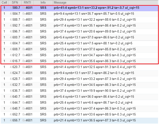
According to the Rrc Configuration shown above, following bandwidth configuration is used. This indicates that one SRS will transmit the reference signal in 4 consecutive PRBs.
Following is the result of SRS received and measured by Amari Callbox. You would notice that each SRS transmit the signal across 4 consecutive PRB, each SRS is transmitted with 4 radio frames (40 ms, 800 slots). It takes 80 radio frames (40 ms, 800 slots) to transmit SRS across the whole bandwidth. The pattern in red box (40 radio frames) repeats
Example 02 > Periodic 80 ms, c-SRS 13, b-SRS 1, b-hop 0
This is an example of Periodic SRS captured by Amari Callbox and commercial UE.
SIB 1 :
servingCellConfigCommon {
downlinkConfigCommon {
frequencyInfoDL {
frequencyBandList {
{
freqBandIndicatorNR 78
}
},
offsetToPointA 24,
scs-SpecificCarrierList {
{
offsetToCarrier 0,
subcarrierSpacing kHz30,
}
}
},
RrcSetup :
srs-Config setup: {
srs-ResourceSetToAddModList {
{
srs-ResourceSetId 0,
srs-ResourceIdList {
0
},
},
usage codebook,
p0 -76,
pathlossReferenceRS ssb-Index: 0
}
},
srs-ResourceToAddModList {
{
srs-ResourceId 0,
nrofSRS-Ports port1,
transmissionComb n2: {
combOffset-n2 0,
cyclicShift-n2 4
},
resourceMapping {
startPosition 0,
nrofSymbols n1,
repetitionFactor n1
},
freqDomainPosition 0,
freqDomainShift 5,
},
groupOrSequenceHopping neither,
resourceType periodic: {
},
sequenceId 500
}
}
}
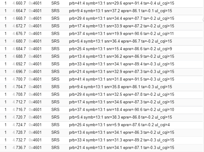
According to the Rrc Configuration shown above, following bandwidth configuration is used. This indicates that one SRS will transmit the reference signal in 24 consecutive PRBs.
Following is the result of SRS received and measured by Amari Callbox. You would notice that each SRS transmit the signal across 24 consecutive PRB. It takes 4 radio frames (40 ms, 80 slots) to transmit SRS across the whole bandwidth. The pattern in red box (4 radio frames) repeats

Reference
[1] 3GPP TSG RAN WG1 Ad Hoc-1801 Meeting : R1-1801085 - Summary of SRS
[2] 3GPP TSG RAN WG1 Ad Hoc Meeting : R1-1800090 - Summary of remaining details of SRS design
[3] 3GPP TSG RAN WG1 Meeting AH 1801 : R1-1800370 - Clarification on intra-slot hopping for aperiodic SRS
[4] 3GPP TSG RAN WG1 Meeting AH 1801 : R1-1800439 - Issues on SRS
[5] 3GPP TSG RAN WG1 Meeting AH 1801 : R1-1800116 - Remaining details on SRS