NR scheduling offers super wide flexibility that get so many factors involved. However, in practice 'wide flexibility' often mean 'too high degree of complexity', 'difficulties of understanding the details' and 'confusion'. Mainly due to this complexity, I have written several individual notes that are directly or indirectly related to NR scheduling. Followings are the list of my notes related to NR scheduling. Don't try to understand all of these at once. You may get overwhelmed and may end up with early give-up. Start with reading through these notes without being pressured to understand all the details with the first read. Just try to pick up some terminologies and factors related to scheduling.
- Scheduling Overview
- K0,K1,K2,N1,N2
- SLIV
- DCI 1_0,1_1,0_0,0_1
- TDD UL/DL Configuration Common
- TDD UL/DL Configuration Dedicated
- HARQ Process
- Get the Test Procedure and Log / Amarisoft TechAcademy
In this note, I want to approach NR scheduling with more of practical perspectives with the minimum set of factors. At least as of now (Oct 2021), the industry seems to keep the scheduling as simple as possible and not to enable tricky features (e.g, configured scheduling, SFI and introduction of cancellation, interruption etc) which may lead to too much complication and unstability of the scheduling.
If you are interested in NR scheduling, it would be good idea to have a firm understandings on this note and try to deepen / widen the knowledge and experience from there.
- Downlink Scheduling
- Uplink Scheduling
- Putting them all together
- Example 01 : DDDDSDDDDS
- Example 02 : DDDDSDDDDS
- Example 03 : DDDUSDDDUS
- Example 04 : DDDDSDDSUU
- Example 05 : XDDXSDDSXU
- Special Considerations on Scheduling
- Reference
Downlink Scheduling
Now let's look into a typical downlink scheduling (i.e, PDSCH scheduling). This process can be illustrated as follows, the process can be summarized as follows.
i) NW (Network) send DCI for PDSCH (PDSCH Grant)
ii) After K0 slots after the DCI, PDSCH is transmitted (K0 can be any value from 0 through 32, but as of Sep 2021, only K0 = 0 seems to be supported).
iii) After k1 slots after the PDSCH is transmitted, UE transmit Ack/Nack via UCI. The UCI can be carried by PUCCH or PUSCH depending on situations. The slot carrying the UCI can be utilized in various different form which can be examplified as Case 1,2,3,4 as shown below).

Read the drawing from the bottom up. The row of slots along the bottom is the timeline. A red DCI sits in the first slot. K0 carries you to the slot holding the PDSCH, and K1 carries you from there to the slot holding the UCI. The four Case rows stacked above are not four different procedures. They are four shapes that one UCI slot can take.
Case 1 is the plain one : the slot carries nothing but the Ack/Nack, drawn as a small blue block at the end. The UCI travels on PUCCH.Case 2 puts a fresh grant in the same slot : a DCI and a PDSCH sit at the front, and the UCI still goes on PUCCH at the end. The green annotation marks the DL to UL symbol gap, which the UE needs in order to switch from receiving to transmitting. It is at least 1 symbol in FR1 and 2 symbols in FR2.Case 3 is the one that changes channel : the slot already carries a PUSCH, so the UCI is piggybacked onto it rather than sent on PUCCH.Case 4 keeps both apart : there is a PUSCH in the slot and the UCI still goes on PUCCH beside it.
The two offsets come from different places, and that is worth knowing when a value looks wrong in a log. K0 is not signalled as a number at all. The Time domain resource assignment field of the DCI indexes a row in a resource allocation table. 38.214 says that row is what defines the slot offset K0, along with the SLIV.
K1 is chosen differently. The network configures a list of candidate values in
Uplink Scheduling
Uplink is shorter to describe because one arrow is missing from it. Downlink needed a return path for the Ack/Nack, and that is what forced K1 and the four UCI cases above. Uplink has no such report, so the whole procedure collapses to a grant and a transmission.
Uplink scheduling is relatively simple comparing the downlink scheduling explained in previous section. Overall procedure is as follows.
i) Network send UL Grant(DCI 0_0 or DCI 0_1).
ii) After K2 slot after the DCI slot, UE transmit PUSCH.

One slot, one grant, one PUSCH : the red DCI block sits in the first slot, and the magenta PUSCH box sits in a later one. Nothing in between needs arranging.K2 spans the gap : the green arrow runs from the DCI slot to the PUSCH slot, and it is the only timing relationship in the picture.Nothing comes back : there is no third arrow, because the network never sends an Ack or a Nack for a PUSCH.
K2 is derived exactly the way K0 is. The Time domain resource assignment field of the UL grant indexes a row in a resource allocation table. 38.214 says the indexed row defines the slot offset K2 together with the SLIV. So the same field name in a DCI 0_0 and a DCI 1_1 points at two different tables. A value read from one tells you nothing about the other.
The absence of a feedback arrow is what makes the NDI so important. With no Ack or Nack to read, the UE cannot know from the network's silence whether a PUSCH arrived. It learns from the next grant instead. A toggled NDI means this is new data, and an untoggled NDI on the same HARQ process means send that transport block again.
One practical consequence follows. A retransmission and a fresh transmission look identical on the air, and only the NDI bit in the grant separates them. When throughput drops without any obvious error, counting untoggled NDI values in the grants is usually a faster diagnosis than looking at the PUSCH itself.
Putting them all together
The scheduling procedure describe in previous section is for the scheduling in single cycle (i.e, single HARQ process). If only the single cycle (single HARQ) is used, there would be a lot of slots being idle(i.e, not scheduled) because almost always there are some slots not scheduling between PDSCH and UCI, and between DCI and PUSCH. So in most of real situation, multiples of those individual process (individual HARQ processes) are running in interleaving fashion and it can minimize the number of not-used slots.
In this section, I will show you some of the examples of the scheduling you may see in live network situation or test setups for high throughput. These are only a few examples, there can be almost infinite number of different way of scheduling method.
Example 01 : DDDDSDDDDS
In this example, the scheduling is done in periodic fashion. Each period spans 5 slots in which the first 4 slot is scheduled for PDSCH and the fifth slot is reserved for UCI. Ack/Nack for all the PDSCH within the 5 slot span is conveyed by the single UCI in the fifth slot. Looking further into UCI slot, it can be scheduled as in a case out of 4 cases shown here.

Example 02 : DDDDSDDDDS
In terms of overall slot configuration, the pattern in this example is same as the pattern in previous example. The difference from the previous example is that UCI for some PDSCH within a period is mapped to the UCI slot in next period. Like a previous example, the UCI slot can be scheduled as in a case out of 4 cases shown here.
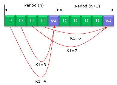
Example 03 : DDDUSDDDUS
This example also shows a scheduling with a specific pattern(5 slot pattern) where the first 3 slots are scheduled for PDSCH and the 4th slot is scheduled for PUSCH and the last (5th slot) is reserved for UCI. Like a previous example, the UCI slot can be scheduled as in a case out of 4 cases shown here.

Example 04 : DDDDSDDSUU
In this example, I just try to break the pattern to show you that the scheduling can be done in any arbitray way. I put the first 5 slots in the same pattern as in example 01 and in the second 5 slots I put 2 PDSCH at the beginning and 2 PUSCH slots at the end and put UCI slot in the middle. In terms of UCI transmission as well, I mapped one UCI in the same way as above and mapped another UCI to PUSCH.
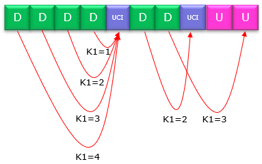
Example 05 : XDDXSDDSXU
The previous examples would show you the most of the cases for scheduling regular slots (By regular slot, I mean those slots that can be fully allocated for user data(e.g, PDSCH, PUSCH) and control information (e.g, DCI, UCI)). But there are some slots that cannot be used fully for user data and control information. Let me call this as a 'special purpose slot' (this is not 3GPP term). By special purpose slot, I mean those slots transmitting special reference signals (e.g, SSB, CSI-RS, TRS) or reserved for special usage(e.g, Rach Occasion(RO)). Following is an example of these special purposed slots scattered here and there between regular slots.
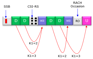
For the regular slots you may schedule the same way as you saw in previous examples, but what about those special purpose slots (i.e, SSB slot, CSI-RS slot, RO slot) ?
Just for perspective of scheduling, the simplest way is 'Do NOT schedule/allocate any PDSCH, PUSCH' in these slots. It can avoid many problems that can happen related to channel encoding/decoding. In reality, at early implementation / deployment of 5G, you might have seen those cases where network does not allocate PDSCH or PUSCH in those special purpose slots.
However utilizing those slots only for transmitting / receiving the special signals is waste of resources because the number of resources (i.e, Resource Elements) required for those special signal is very small portion comparing to the whole resources available for those slots. As 5G/NR implementation and deployment gets more mature, you would see more and more of those cases where even these special purpose slots are utilized for transmitting or receiving user data. 3GPP allows or provide mechanisms to transmit/recieve user data in these special purpose slots from the beginning (i.e, Release 15), but in early implementation those special purpose slots tend NOT to be used for user data.
Special Considerations on Scheduling
What I have described above is based on typical scheduling that are commonly practiced in the live network or testing environment. Most of the cases shown above would look obvious to you, but there are many cases where the scheduling may not look obvious especially when the scheduling(Scheduling by DCI 1_x and DCI 0_x) is done when tdd-UL-DL Configcommon / tdd-UL-DL ConfigDedicated are configured or SlotFormat Combination is configured by Rrc and SFI (DCI 2_x).
Reference
[1]