As mentioned in the deployment Scenario, NR can be introduced in multiple ways depending on the operator strategy and network maturity. At the early stage of NR rollout, it is very common that NR does not operate as a fully independent system. Instead, it works together with LTE, where LTE provides the main control connection and NR provides additional data capacity. In this configuration, LTE acts as the Master Node and NR acts as the Secondary Node. This deployment is called NSA, meaning Non-Standalone deployment. The key idea is that the network can quickly introduce NR benefits such as higher throughput without rebuilding the entire core and control framework.
In NSA, the UE maintains a primary connection with LTE. This connection handles signaling and mobility control. At the same time, the UE can establish an additional connection with NR to boost user plane data performance. This combined operation is defined under MR-DC, which stands for Multi-Radio Dual Connectivity. The specification defines several ways to construct the bearer architecture in this setup, and these are captured in 3GPP specifications such as 37.340 as below
From the UE perspective, there are three main types of bearers in MR-DC. The first is the MCG bearer. This bearer is fully handled by the LTE side, meaning both control and data flow go through the Master Node. The second is the SCG bearer. This bearer is handled entirely by the NR side, meaning the data flows through the Secondary Node. The third type is the split bearer. This is the most interesting and sometimes confusing one. In this case, a single data flow is split across both LTE and NR simultaneously. This allows the network to utilize resources from both nodes at the same time and achieve higher throughput and better load balancing.
The behavior of these bearers depends on the specific MR-DC architecture. For example, in EN-DC, which uses EPC as the core network, LTE remains the anchor for control signaling. In NG-EN-DC or NE-DC, which involve the 5G Core, the roles and signaling paths can be slightly different, but the basic concept of MCG, SCG, and split bearer remains the same.
Among these, the split bearer requires deeper understanding because the data is divided at a certain protocol layer and transmitted over two different radio links. This involves additional coordination between the Master Node and Secondary Node, as well as reordering and recombining data at the UE side. Because of this complexity, the split bearer often becomes a key topic when analyzing NSA performance and troubleshooting data flow behavior.
In this page, the focus is on explaining this split bearer concept in detail. The goal is to clearly show how the data is divided, how each part flows through LTE and NR, and how the UE reconstructs the original data stream. This helps in understanding the real benefit and the internal mechanism of MR-DC operation.
In this page, I will explain only on a specfic type of bearer mentioned above called 'Split Bearer' since it may be a kind of confusing concept.
- Which Bearer ? Which Split ?
- SplitBearer Usecase in deployment scenario
- Exact Point of Split in Radio Bearer
- How the throuput gets split ?
- RRC Parameters
- Get the Test Procedure and Log / Amarisoft TechAcademy
The previous discussion explained that data can be carried through both LTE and NR in NSA or MR-DC. This part explains exactly where that split happens in the protocol stack and why the term can be confusing. The main purpose of this page is to separate two different ideas that often look similar in diagrams but mean very different things in practice.
The term 'SplitBearer' can be confusing because the two keywords 'Bearer' and 'Split' would be confusing terms. Let's clarify on these two keywords first.
What does it mean by Bearer ?
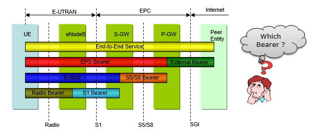
The first point is the meaning of bearer. In telecom, bearer does not simply mean any generic connection. It means a logical data path with a certain service characteristic. There are several bearer concepts in the end to end system, such as EPS bearer, E-RAB, and S1 bearer. But when this page talks about split bearer, it is focusing on the radio bearer. This is the bearer that exists over the radio side between the network node and the UE. So the discussion is not about splitting the entire end to end connection at every layer. It is specifically about how the radio side data path is organized.
First, let's think of what kind of Bearer are defined. In case of LTE, roughly several different types of Bearer are defined as shown below (I would not describe any detailed on each of these bearers here). Just as a conclusion, when we say 'SplitBearer', the Bearer in this case is more related to the last one. More accurate location of bearer split will be explained later.
What does it mean by Split ?
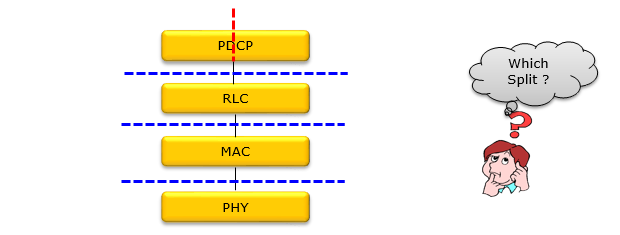
The second point is the meaning of split. This is the most important part of the page. The red dotted line (shown in the illustration below) indicates the true split bearer mechanism. It indicatest this split happens inside the PDCP layer. In this architecture, one PDCP entity receives the upper layer packets and sends them down into two lower paths. One path goes to an RLC entity associated with LTE. The other path goes to an RLC entity associated with NR. This is why it is called split bearer. One logical radio bearer at the PDCP level is divided into two radio transmission paths below it. This allows the network to use both LTE and NR resources together for the same user data flow.
Any Horizontal Split ?
This diagram shown above highlights another possible interpretation of �split� and explains why that interpretation is not what we mean when discussing split bearer. At a quick glance, the blue dashed horizontal lines suggest that the protocol stack itself can be divided into multiple sections. In a purely logical sense, you can imagine cutting the stack at different layer boundaries such as between PDCP and RLC, or between RLC and MAC. This kind of division is what we call a horizontal split.
In real deployments, this horizontal split is used for architectural separation such as CU and DU split (CU/DU Separation). In this case, upper layers like PDCP may run in a centralized unit, while lower layers like RLC, MAC, and PHY run in a distributed unit closer to the radio. This type of split is about how the system is implemented and where each protocol function resides. It is a deployment and hardware architecture decision.
However, this is NOT the split that is meant in split bearer. The key point of this page is to remove that confusion. Even though the horizontal split looks like a �division� in the protocol stack, it does not represent the data path being divided across multiple radio links. It simply represents that different layers are located in different physical nodes.
When we talk about split bearer, the split is vertical in terms of data flow. It happens inside the PDCP layer, where one data stream is divided and sent down to multiple RLC entities. Each of those RLC entities is associated with a different radio leg, such as LTE and NR. So the split bearer is about branching the traffic, not about separating protocol layers.
So the main message of this image is straightforward. A horizontal split is a functional or deployment separation of protocol layers, such as CU and DU. It does not create multiple parallel radio paths for the same data. The real split bearer is different. It is a traffic split inside PDCP that enables simultaneous transmission over multiple radio nodes.
Putting it together
In conclustion, Split bearer means traffic branching within the bearer handling path, specifically at PDCP, toward multiple radio legs. Separation means protocol functions are located in different boxes or hardware locations. One is about traffic flow. The other is about functional distribution.
So the overall lesson is simple. Bearer in this context means radio bearer. Split means the PDCP layer sends one data stream into two radio paths such as LTE and NR. Separation means the protocol stack itself is distributed across different units such as CU and DU. Once this distinction is clear, the overall NSA and MR-DC bearer architecture becomes much easier to understand.
SplitBearer Usecase in deployment scenario
This section shifts the discussion from the internal mechanism of split bearer to how it is actually realized in a live network. The previous images explained what a split bearer is and where the split happens in the protocol stack. This image explains when operators use it and how the network nodes are connected to support it.
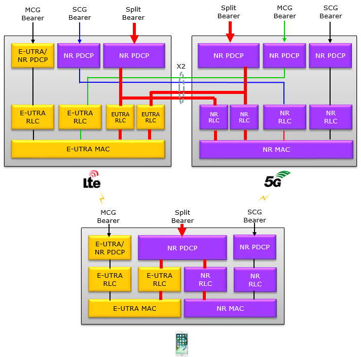
The key concept here is MR-DC, meaning Dual Connectivity. In this setup, the UE is simultaneously connected to two radio nodes. One node plays the role of Master Node and the other plays the role of Secondary Node. The Master Node is responsible for maintaining the main connection with the core network, while the Secondary Node provides additional radio resources mainly for data throughput improvement.
The image shows different deployment cases depending on which core network is used. In the most common case, often referred to as Case 4, the system uses the LTE core network, EPC. In this configuration, LTE eNB acts as the Master Node and NR gNB acts as the Secondary Node. The UE connects first to LTE, and then NR is added as an auxiliary link. This is the typical NSA deployment that most operators used in the early phase of 5G rollout.
A more advanced case, such as Case 6, uses the 5G core network. In this case, the architecture is more evolved, but the basic idea of dual connectivity still applies. The Master Node role can still be associated with LTE in certain configurations, but the core network handling is now based on 5GC. This provides more flexibility and supports newer 5G features.
Another important point shown in the image is the clear separation between control plane and user plane. The control plane always remains anchored at the Master Node. This means signaling, connection management, and mobility procedures are handled by LTE in NSA. The user plane, which carries actual data traffic, is where the split bearer operates. The data can be transmitted partly through LTE and partly through NR at the same time.
So the split bearer becomes a real physical routing behavior in this architecture. The PDCP entity in the Master Node decides how to distribute packets. Some packets go down the LTE path. Others go down the NR path. Both paths are active simultaneously, and the UE combines the data from both links.
The reason Case 4 became the most widely deployed scenario is mainly practical. Operators could reuse their existing LTE infrastructure and core network. This minimized cost and allowed faster deployment of 5G services. LTE provides stable coverage and control signaling, while NR provides high data rates. Split bearer is the mechanism that allows these two systems to work together efficiently.
So overall, this image completes the full picture. Split bearer is not just a protocol concept. It is a system-level feature enabled by dual connectivity. It relies on a Master Node for control, a Secondary Node for additional capacity, and a coordinated user plane where data is split and transmitted over multiple radio links.
In practice, < Case 4 > is the most common depolyment method when we deploy LTE and NR in dual carrier mode.

This diagram shown above focuses on how split bearer is realized in a real network environment. It connects protocol behavior with actual network architecture. It can be verbalized as below
Dual Connectivity Concept (MR-DC) - UE connects to two radio nodes simultaneously
- One node is Master Node (MN) and the other is Secondary Node (SN)
- MN maintains the main connection to the core network
- SN provides additional radio resources mainly for higher throughput
Deployment Cases Based on Core Network - Case 4 (Most common NSA deployment)
- Uses EPC (LTE core network)
- LTE eNB acts as Master Node
- NR gNB acts as Secondary Node
- UE first connects to LTE, then NR is added as secondary link
- Case 6 (More advanced deployment)
- Uses 5GC (5G Core)
- Still supports dual connectivity structure
- Provides more flexibility and supports newer 5G features
- Case 4 (Most common NSA deployment)
Control Plane vs User Plane - Control Plane (CP)
- Always anchored at Master Node
- Handles signaling, mobility, connection management
- User Plane (UP)
- Carries actual user data such as video, download, web traffic
- This is where split bearer operates
- Control Plane (CP)
How Split Bearer Works in Deployment - PDCP entity at Master Node controls data distribution
- One data flow is divided into multiple paths
- One path goes through LTE (MCG leg)
- Another path goes through NR (SCG leg)
- UE receives data from both paths and recombines them
Why Case 4 is Widely Used - No need to replace existing EPC infrastructure
- Faster time-to-market for 5G services
- LTE provides stable coverage and control
- NR provides high data rate enhancement
Overall Meaning - Split bearer is not only a protocol concept
- It is a system-level feature enabled by dual connectivity
- It allows LTE and NR to work together efficiently for a single data flow
Exact Point of Split in Radio Bearer
Now let's look more in details on what's happening inside the radio bearer with split bearer. Following is the illustration highlighting the data path of splitbearer based on 37.340 - Figure 4.2.2-3 and Figure 4.2.2-1. Following through the solid red arrows and lines, you would read out followings :
- In splitbearer, NR PDCP is used both in LTE Anchor and NR.
- Splitting of data stream is done by PDCP
LTE-Anchored 5G NSA (EN-DC) Architecture: Bearer Paths and Interfaces
The following diagram shows the overall EN-DC (Option 3) blueprint in one view. It separates the network into two planes. One plane is for control. The other plane is for user data.
The control plane is LTE anchored. The UE talks to the MeNB for RRC and mobility control. The MeNB talks to the LTE core through S1-MME. This means connection management is handled by LTE even though NR is also active.
The user plane can use multiple paths. User data from the core can reach the MeNB and be delivered over LTE. It can also be sent to the SgNB side so NR can carry user traffic. This is how the network enables NR throughput while keeping LTE as the anchor.
The key link between MeNB and SgNB is the X2 interface. This interface is the bridge that makes dual connectivity practical. In split bearer operation, the MeNB receives the downlink data and then forwards part of it to the SgNB over X2. The UE then receives data over LTE and NR in parallel.
Split bearer behavior confirms that the MeNB is the master for data flow in Option 3. The MeNB PDCP decides how to distribute traffic between LTE and NR. The SgNB mainly acts as an additional radio leg that boosts capacity.
This architecture works well only when the X2 transport is good. If X2 latency or jitter is large, the benefit of NR aggregation drops. It can also increase buffering and reordering effort at PDCP.
At the UE side, two radios are effectively active. LTE and NR are received simultaneously. The UE must support dual connectivity and must handle parallel scheduling and reordering across the two legs.
Followings are bulleted description of the diagram shown above
What this diagram represents - It is a high-level map of EN-DC (Option 3) architecture
- It shows how LTE-anchored 5G NSA connects the UE to the core network
- It separates the system into Control Plane and User Plane paths
Control Plane stays on LTE (MeNB anchored) - UE control signaling is handled by the MeNB
- MeNB connects to the EPC control entity through S1-MME
- Mobility and connection management are handled by LTE even when NR is active
User Plane can use LTE, NR, or both - MCG bearer delivers user data via LTE only
- SCG bearer delivers user data via NR while control is still anchored on LTE
- Split bearer delivers user data via LTE and NR in parallel
X2 interface is the bridge between MeNB and SgNB - It enables coordination between LTE and NR nodes for dual connectivity
- In split bearer operation
- Downlink user data arrives at the MeNB side first
- MeNB forwards part of the data to the SgNB over X2
- UE receives data over LTE and NR simultaneously
Split bearer in Option 3 is MN-terminated - The split decision is controlled by the MeNB side
- MeNB PDCP decides how traffic is distributed between LTE and NR
- SgNB mainly provides extra radio capacity under MeNB control
Performance depends on X2 transport quality - Low X2 latency and jitter are needed to realize the NR throughput gain
- Poor X2 transport reduces aggregation gain and can increase buffering and reordering impacts
UE requirements - UE must support dual connectivity (LTE and NR active in parallel)
- UE must handle parallel scheduling and PDCP reordering across two legs
PDCP Data Path Overview in NR/LTE: Header Handling, Security, and Reordering
Now getting further into details, let's think of exactly at which point within PDCP the split happens. According to 38.323 4.2.2 PDCP entities, it is stated as follows :
In 3GPP NR Specification, not so much details are explained about SplitBearer mechanism. For now, you may get a little bit more detailed idea from LTE specification described in 36.323 4.2.2 PDCP entities. This is the specification for LTE Dual Connectivity (not NR splitbearer) but I think similar idea would apply to NR split bearer as well.
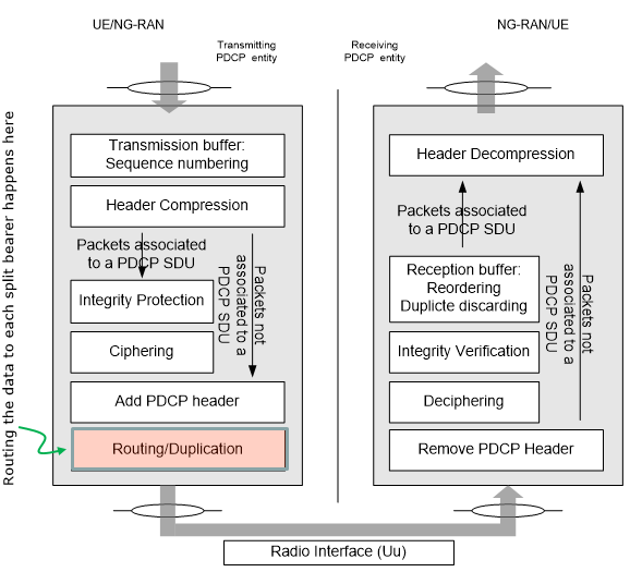
This diagram shows the end-to-end processing flow inside the PDCP layer. It compares the transmitting PDCP entity on the left and the receiving PDCP entity on the right. The main point is that PDCP is not only doing security and header handling. It is also the layer where routing or duplication can be applied, which is the key mechanism used for split bearer behavior.
On the transmit side, PDCP takes packets that are associated with a PDCP SDU and prepares them for radio delivery. It assigns sequence numbers in the transmission buffer so the receiver can later reorder packets. It can compress IP headers to reduce overhead. It then applies integrity protection and ciphering. After that it adds the PDCP header to form PDCP PDUs.
The highlighted block at the bottom, routing or duplication, is where PDCP decides how to send the PDCP PDUs over the radio legs. In a normal bearer, this simply forwards PDCP PDUs down to lower layers. In dual connectivity cases, this is where PDCP can distribute PDUs across different legs or duplicate them for reliability. This is why the image says the split bearer routing happens here.
On the receive side, PDCP reverses the process. It removes the PDCP header, decrypts the data, and verifies integrity. Then it uses the reception buffer to reorder packets based on sequence numbers and discard duplicates if the same packet arrived more than once. Finally, it decompresses headers and outputs packets back as PDCP SDUs to upper layers.
The bottom �Radio Interface (Uu)� indicates that everything between these two PDCP entities crosses the air interface through the lower layers. The diagram therefore explains why PDCP is the natural control point for split bearer features. It is the first place where packets are numbered and the last place where packets are reassembled and deduplicated.
Following is the bulleted description of the diagram shown above
What the diagram shows - It illustrates PDCP processing on both ends of the radio link
- Left side is the transmitting PDCP entity (UE or NG-RAN)
- Right side is the receiving PDCP entity (NG-RAN or UE)
- The Radio Interface (Uu) is between the two PDCP entities
Transmitting PDCP entity functions (left) - Transmission buffer performs sequence numbering
- Header compression reduces IP header overhead
- Integrity protection is applied when configured
- Ciphering is applied for confidentiality
- PDCP header is added to form PDCP PDUs
Routing or duplication point (highlighted) - This is where PDCP decides how PDCP PDUs go down toward the radio
- In dual connectivity, traffic can be distributed across multiple legs
- In duplication mode, the same PDCP PDU can be sent on multiple paths
Receiving PDCP entity functions (right) - PDCP header is removed
- Deciphering is performed
- Integrity verification is performed when configured
- Reception buffer performs reordering using sequence numbers
- Duplicate discarding removes repeated PDUs
- Header decompression restores the original packet header form
Key takeaway - PDCP is the control point for split bearer behavior
- Sequence numbering, reordering, and duplicate handling enable routing, splitting, and duplication decisions
How the throuput gets split ?
Before I talk about 'How', let me ask 'Who is going to split the data ?' Is it UE or NW ? Obviously it is UE. It means that the decision making for the split is done on UE side. It may sound obvious, but I often forgot about the simple fact and get confused about the split process.
There are several factors configured by RRC to affect on the decision making on split as shown below.
moreThanOneRLC SEQUENCE {
primaryPath SEQUENCE {
cellGroup CellGroupId OPTIONAL, -- Need R
logicalChannel LogicalChannelIdentity OPTIONAL -- Need R
},
ul-DataSplitThreshold UL-DataSplitThreshold OPTIONAL, -- Cond SplitBearer
pdcp-Duplication BOOLEAN OPTIONAL -- Need R
} OPTIONAL, -- Cond MoreThanOneRLC
UL-DataSplitThreshold ::= ENUMERATED {
b0, b100, b200, b400, b800, b1600, b3200, b6400, b12800, b25600, b51200, b102400, b204800,
b409600, b819200, b1228800, b1638400, b2457600, b3276800, b4096000, b4915200, b5734400,
b6553600, infinity, spare8, spare7, spare6, spare5, spare4, spare3, spare2, spare1}
Overall procedure may go like this :
- If the cellGroup is set to 0 which means MCG (indicating LTE in ENDC), the amount of data upto ul-DataSplitThreshold is transmitted through LTE and the remaining data is going through NR cell.
- If the cellGroup is set to 1 which means SCG (indicating NR in ENDC), the amount of data upto ul-DataSplitThreshold is transmitted through NR and the remaining data is going through LTE cell
i) pick a logical channel specified by LogicalChannelIdentity specified by RRC
ii) estimate how much data the UE has to transmit (this process is tightly related to the data volumn calculation in BSR process)
iii) Based on the estimated data volumn, UE need to determine whether it need split or not. The criteria of this decision is configured by ul-DataSplitThreshold in Rrc. If the estimated data volumn is less than the threshold it does not split and if the data volumn is greater than the threshold it need to split.
iiii) Once it is decided to split the data, now it has to determine how much portions of the data to be transmitted through each cell. This is determined by cellGroup in Rrc.
Sound simple, but there are two confusing parameters in ul-DataSplitThreshod. They are b0 and Infinity. If b0 is set, It does not mean 'no split'. It indicates UE determine the split ratio by its own algorithm. If Infinity is set, UE send 100% of the data via the cell specified in cellGroup.
Following is formal description of split mechanism described in 3GPP.
38.323-5.2.1 states : (I am always struggling this kind of pseudo-code style description WITHOUT BRACKET.. easily lose track while reading -:). The part highlighed red would be about SplitBearer operation.
When submitting a PDCP PDU to lower layer, the transmitting PDCP entity shall:
if the transmitting PDCP entity is associated with one RLC entity:
submit the PDCP PDU to the associated RLC entity;
else, if the transmitting PDCP entity is associated with at least two RLC entities:
if the PDCP duplication is activated for the RB:
if the PDCP PDU is a PDCP Data PDU:
duplicate the PDCP Data PDU and submit the PDCP Data PDU to the associated RLC entities activated for PDCP duplication;
else:
submit the PDCP Control PDU to the primary RLC entity;
else (i.e. the PDCP duplication is deactivated for the RB or the RB is a DAPS bearer):
submit the PDCP PDU to either the primary RLC entity or the split secondary RLC entity;
else, if the transmitting PDCP entity is associated with the DAPS bearer:
if the uplink data switching has not been requested:
submit the PDCP PDU to the RLC entity associated with the source cell;
else:
if the PDCP PDU is a PDCP Data PDU:
submit the PDCP Data PDU to the RLC entity associated with the target cell;
else:
if the PDCP Control PDU is associated with source cell:
submit the PDCP Control PDU to the RLC entity associated with the source cell;
else:
submit the PDCP Control PDU to the RLC entity associated with the target cell;
else:
submit the PDCP PDU to the primary RLC entity
Now let go to 38.322 and see what happen.. (It would be more appreciated if 3GPP TS authors put section/chapter number as well when they referring to other document -:). For this part, I would suggest you to look into the note on BSR rather than putting those details in this note.
RRC Parameters
PDCP-Config ::= SEQUENCE {
drb SEQUENCE {
discardTimer ENUMERATED {ms10, ms20, ms30, ms40, ms50, ms60, ms75, ms100, ms150, ms200,
ms250, ms300, ms500, ms750, ms1500, infinity} OPTIONAL, --Cond Setup
pdcp-SN-SizeUL ENUMERATED {len12bits, len18bits} OPTIONAL, -- Cond Setup2
pdcp-SN-SizeDL ENUMERATED {len12bits, len18bits} OPTIONAL, -- Cond Setup2
headerCompression CHOICE {
notUsed NULL,
rohc SEQUENCE {
maxCID INTEGER (1..16383) DEFAULT 15,
profiles SEQUENCE {
profile0x0001 BOOLEAN,
profile0x0002 BOOLEAN,
profile0x0003 BOOLEAN,
profile0x0004 BOOLEAN,
profile0x0006 BOOLEAN,
profile0x0101 BOOLEAN,
profile0x0102 BOOLEAN,
profile0x0103 BOOLEAN,
profile0x0104 BOOLEAN
},
drb-ContinueROHC ENUMERATED { true } OPTIONAL -- Need N
},
uplinkOnlyROHC SEQUENCE {
maxCID INTEGER (1..16383) DEFAULT 15,
profiles SEQUENCE {
profile0x0006 BOOLEAN
},
drb-ContinueROHC ENUMERATED { true } OPTIONAL -- Need N
},
...
},
integrityProtection ENUMERATED { enabled } OPTIONAL, -- Cond ConnectedTo5GC
statusReportRequired ENUMERATED { true } OPTIONAL, -- Cond Rlc-AM
outOfOrderDelivery ENUMERATED { true } OPTIONAL -- Need R
} OPTIONAL, -- Cond DRB
moreThanOneRLC SEQUENCE {
primaryPath SEQUENCE {
cellGroup CellGroupId OPTIONAL, -- Need R
logicalChannel LogicalChannelIdentity OPTIONAL -- Need R
},
ul-DataSplitThreshold UL-DataSplitThreshold OPTIONAL, -- Cond SplitBearer
pdcp-Duplication BOOLEAN OPTIONAL -- Need R
} OPTIONAL, -- Cond MoreThanOneRLC
t-Reordering ENUMERATED {
ms0, ms1, ms2, ms4, ms5, ms8, ms10, ms15, ms20, ms30, ms40,
ms50, ms60, ms80, ms100, ms120, ms140, ms160, ms180, ms200, ms220,
ms240, ms260, ms280, ms300, ms500, ms750, ms1000, ms1250,
ms1500, ms1750, ms2000, ms2250, ms2500, ms2750,
ms3000, spare28, spare27, spare26, spare25, spare24,
spare23, spare22, spare21, spare20,
spare19, spare18, spare17, spare16, spare15, spare14,
spare13, spare12, spare11, spare10, spare09,
spare08, spare07, spare06, spare05, spare04, spare03,
spare02, spare01 } OPTIONAL, -- Need S
...,
[[
cipheringDisabled ENUMERATED {true} OPTIONAL -- Cond ConnectedTo5GC
]]
}
UL-DataSplitThreshold ::= ENUMERATED {
b0, b100, b200, b400, b800, b1600, b3200, b6400, b12800, b25600, b51200, b102400, b204800,
b409600, b819200, b1228800, b1638400, b2457600, b3276800, b4096000, b4915200, b5734400,
b6553600, infinity, spare8, spare7, spare6, spare5, spare4, spare3, spare2, spare1}
RLC-BearerConfig ::= SEQUENCE {
logicalChannelIdentity LogicalChannelIdentity,
servedRadioBearer CHOICE {
srb-Identity SRB-Identity,
drb-Identity DRB-Identity
} OPTIONAL, -- Cond LCH-SetupOnly
reestablishRLC ENUMERATED {true} OPTIONAL, -- Need N
rlc-Config RLC-Config OPTIONAL, -- Cond LCH-Setup
mac-LogicalChannelConfig LogicalChannelConfig OPTIONAL, -- Cond LCH-Setup
...
}