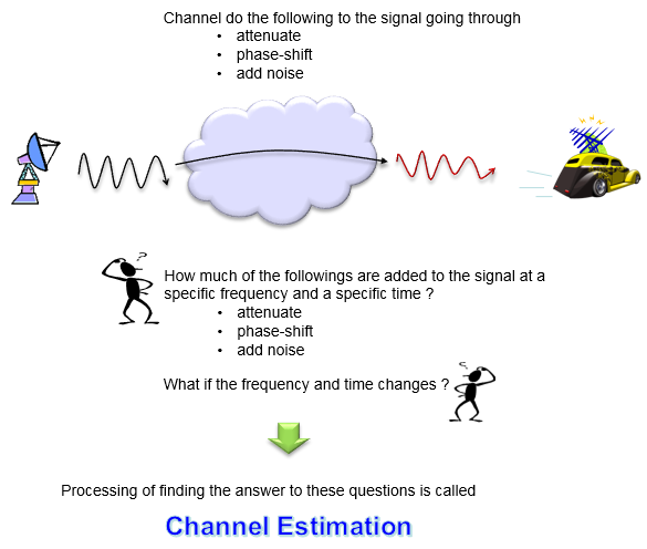
Channel Estimation
As I explained in other pages, in all communication the signal goes through a medium (called channel) and the signal gets distorted or various noise is added to the signal while the signal goes through the channel. To properly decode the received signal without much errors are to remove the distortion and noise applied by the channel from the received signal. To do this, the first step is to figure out the characteristics of the channel that the signal has gone through. The technique/process to characterize the channel is called 'channel estimation'. This process would be illustrated as below.
There are many different ways for channel estimation, but fundamental concepts are similar. The process is done as follows.
i) set a mathematical model to correlate 'transmitted signal' and 'recieved signal' using 'channel' matrix.
ii) Transmit a known signal (we normally called this as 'reference signal' or 'pilot signal') and detect the received signal.
iii) By comparing the transmitted signal and the received signal, we can figure out each elements of channel matrix.
As an example of this process, I will briefly describes on how this process in LTE. Of course, I cannot write down full details of this process in LTE and a lot of details are up to implementation (meaning the detailed algorithm may vary with each specific chipset implmenetation). However, overall concept would be similar.
How can we figure out the properties of the channel ? i.e, how can we estimate the channel ? In a very high level view, it can be illustrated as below. This illustration says followings :
i) we embed the set of predefined signal (This is called a reference signal)
ii) As these reference signal go through the channel, it get distorted (attenuated, phase-shifted, noised) along with other signals
iii) we detect/decode the received reference signal at the reciever
iv) Compare the transmitted reference signal and the received reference signal and find correlation between them.
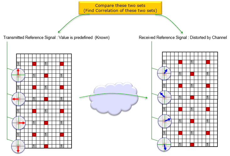
Now let's think of the case of LTE SISO case and see how we can estimate channel properties (channel coefficient and noise estimate). Since this is SISO, reference signal is embedded onto only one antenna port (port 0). The vertical line in the resource map represents frequency domain. So I indexed each of reference signal with f1, f2, f3...fn. Each reference symbol can be a complex number (I/Q data) that can be plotted as shown below. Each complex number (Reference Symbol) on the left (transmission side) is modified (distorted) to each corresponding symbols on the right (recieved symbol). Channel Estimation is the process of finding correlation between the array of complex numbers on the left and the array of complex numbers on the right.
The detailed method of the estimation can very depending on the implementation. The method that will be described here is based on the Open Source : srsLTE (Refer to [1])
< Estimation of Channel Coefficient >
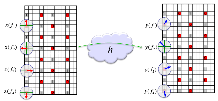
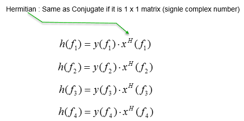
Since this is only one antenna, system model for each transmitted reference signal and received reference signal can be represented as follows. y() represents the array of received reference signal, x() represents the array of transmitted reference signal() and h() represents the array of channel coefficient. f1, f2,... just integer indices.
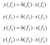
We know what x() are because it is given and the y() is also know because it is measured/detected from the reciever. With these, we can easily calculate coefficient array as shown below.
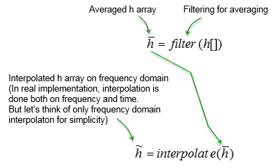
Now we have all the channel coefficient for the location where reference signals are located. But we need channel coeffcient at all the location including those points where there is no reference signal. It means that we need to figure out the channel coefficient for those location with no reference signal. The most common way to do this to this is to interpolate the measured coefficient array. In case of srsLTE, it does a averaging first and then did interpolation over the averaged channel coefficient.
Next step is to estimate the noise properties. Theoretically, the noise can be calculated as below.
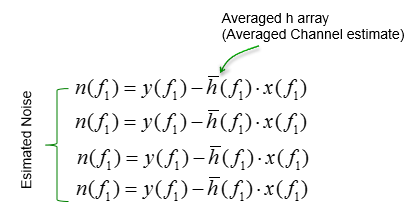
However, what we need is the statistical properties of the noise .. not the exact noise value. we can estimate the noise using only measured channel coefficient and averaged channel as shown below (Actually exact noise value does not have much meaning because the noise value keep changes and it is of no use to use those specific noise value). In srsLTE, the author used this method.
Channel Estimation for 2 x 2 MIMO
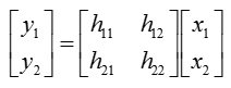
Let's assume that we have a communication system as shown below. x(t) indicates the transmitted signal and y(t) indicates the received signal. When x(t) gets transmitted into the air (channel), it gets distorted and gets various noise and may interfere each other. so the recieved signal y(t) cannot be same as the transmitted signal x(t).
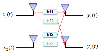
This relation among the transmitted signal, received signal and channel matrix can be modeled in mathematical form as shown below.
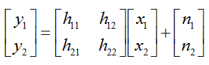
In this equation, we know the value x1,x2 (known transmitted signals) and y1,y2 (detected/recieved signal). The parts that we don't know is H matrix and noise (n1,n2).
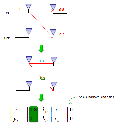
For simplicity, let's assume that there is no noise in this channel, meaning that we can set n1, n2 to be 0. (Of course, in real channel there are always noise and estimate noise is a very important part of channel estimation, but we assume in this example that there is no noise just to make it simple. I will add later the case with noise when I have better knowledge to describe the case in plain language).
Since we have a mathematical model, the next step is to transmit a known signal (reference signal) and figure out channel parameter from the reference signal.
Let's suppose we have sent a known signal with the amplitude of 1 through only one antenna and the other antenna is OFF now. Since the signal propagate through the air and it will be detected by both antenna at the reciever side. Now let's assume that the first antenna received the reference signal with the amplitude of 0.8 and the second antenna received it with amplitude of 0.2. With this result, we can figure out one row of channel matrix (H) as shown below.
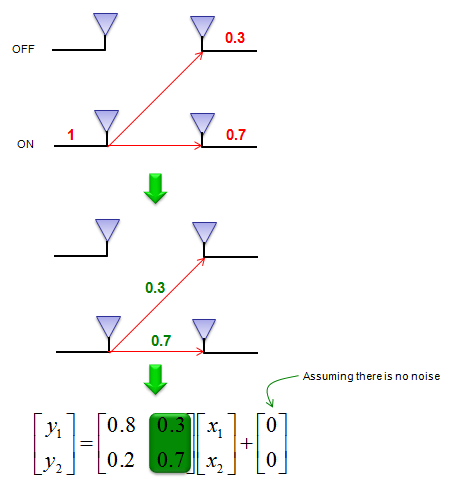
Let's suppose we have sent a known signal with the amplitude of 1 through only the other (second) antenna and the first antenna is OFF now. Since the signal propagate through the air and it will be detected by both antenna at the reciever side. Now let's assume that the first antenna received the reference signal with the amplitude of 0.3 and the second antenna received it with amplitude of 0.7. With this result, we can figure out one row of channel matrix (H) as shown below.
Simple enough ? I think (hope) that you didn't have any problems with understanding this basic concept. But if you use this method exactly as described above, there would be some inefficiency. According to the concept explained above, there should be a moment when you transmit only reference signal without real data just to estimate the channel information, meaning that data rate will be decreased because of channel estimation process. To remove this inefficiency, the real communication system transmit the reference signal and data simulteneously.
Now the question is "How can we implement the concept described above while transmitting the reference signal and data simultaneously ?". There can be several different ways to do this and different communication system would use a little bit of different methodology.
In case of LTE as an example, we use the method described as shown below. In case of 2 x 2 MIMO in LTE, each sub frame has different locations for reference signal for each antenna. The subframe for antenna 0 transmitted the reference signal allocated for antenna 0 and does not transmit any signal at the reference signal allocated for antenna 1. The subframe for antenna 1 transmitted the reference signal allocated for antenna 1 and does not transmit any signal at the reference signal allocated for antenna 0. So if you decode at the two reciever antenna the resource elements allocated for reference signal for antenna 0, you can estimate h11, h12. (here we also assume that there is no noise for simplicity). If you decode at the two reciever antenna the resource elements allocated for reference signal for antenna 1, you can estimate h21, h22. (here we also assume that there is no noise for simplicity).
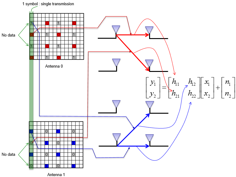
For more detailed explanation, let's assume that you have resource grid data for antenna 0 and antenna 1 as illustrated above. (Regarding how you get the resource grid data at PHY layer DSP level, refer to this note).
h11 = (extracted CRS 0 RE from Antenna 0 resource grid) / (expected CRS 0)
h21 = (extracted CRS 0 RE from Antenna 1 resource grid) / (expected CRS 0)
h12 = (extracted CRS 1 RE from Antenna 0 resource grid) / (expected CRS 1)
h22 = (extracted CRS 1 RE from Antenna 1 resource grid) / (expected CRS 1)
NOTE: Following is a short description each components mentioned above.
- extracted CRS 0 : Resource Element Data extracted from the position of CRS 0 (i.e, these are the received CRS)
- extracted CRS 1 : Resource Element Data extracted from the position of CRS 1 (i.e, these are the received CRS)
- expected CRS 0 : CRS 0 value generated by 3GPP specification (i.e, these are the generated CRS)
- expected CRS 1 : CRS 1 value generated by 3GPP specification (i.e, these are the generated CRS)
In real implementation, you may create separate resource grid for h11, h22, h21, h12 (4 resource grid in 2x2 case) and put the corresponding RE value as described above at every CRS location and then perform frequency and time domain interpolation to fill out entire resource grid as explained in this note) .
< Estimation of Chnnel Coefficient >
The process illustrated above is to measure H matrix for one specific points in frequency domain in a LTE OFDMA symbol. If you apply the measured H value as it is in the process of decoding other parts of symbol, the accuracy of the decoded symbol might not be as good as it can be because the measured data used in previous step would contain some level of noise. So in real application, some kind of post processing is applied to the H values measured by the method described above and in this post processing procedure we could figure out the overal statistical properties of Noise (e.g, mean, variance and statistical distribution of the noise). One thing to keep in mind is that the specific noise value obtained in this process does not have much meaning by itself. The specific value obtained from the reference signal would not be same as the noise value to decode other data (non-reference signal) because the noise value changes randomly. However, the overal properties of those random noise can be an important information (e.g, used in SNR estimation etc).
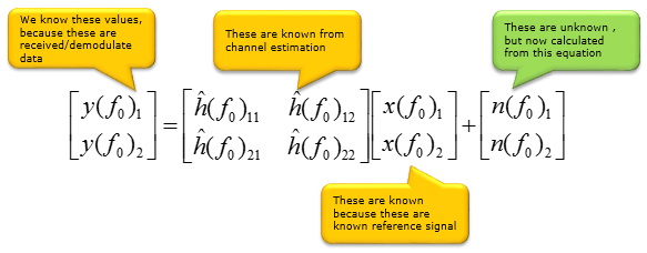
Before moving on, let's briefly think of the mathematical model again. Even though we decribe a system equation as follows including the noise term, it doesn't mean that you can directly measure the noise. It is impossible. This equation just show that the detected signal (y) contains a certain portions of noise component.
So, when we measure the channel coefficient, we used the equipment that does not have noise term as shown below.
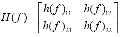
In specific application in LTE, we have multiple measurement points (multiple reference signal) within a OFDM symbol. These measurement points are represented on frequency domain. So, let's rewrite channel matrix as follows to indicate the measurement point of each channel matrix.
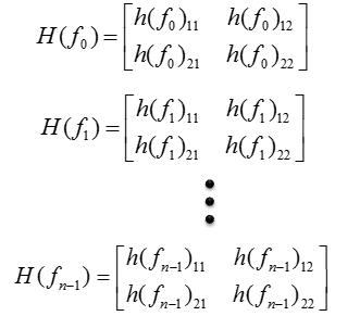
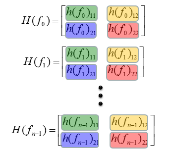
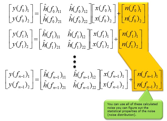
Now let's assume that you have measured H matrix across a whole OFDM symbol, you would have multiple H matrix as below, each of which indicate the H matrix at one specific frequency.
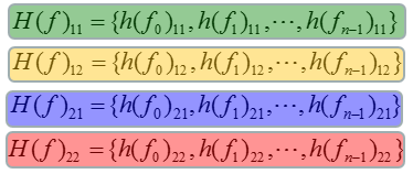
Now you have an array of H matrix. This array is made up of four different group, each of the group is highlighted with different colors as shown below.
When you apply the post processing algorithm, the algorithm needs to be applied to each of these groups separately. So for simplicity, I rearranged the array of H matrix into multiple of independent arrays (4 arrays in this case) as shown below.
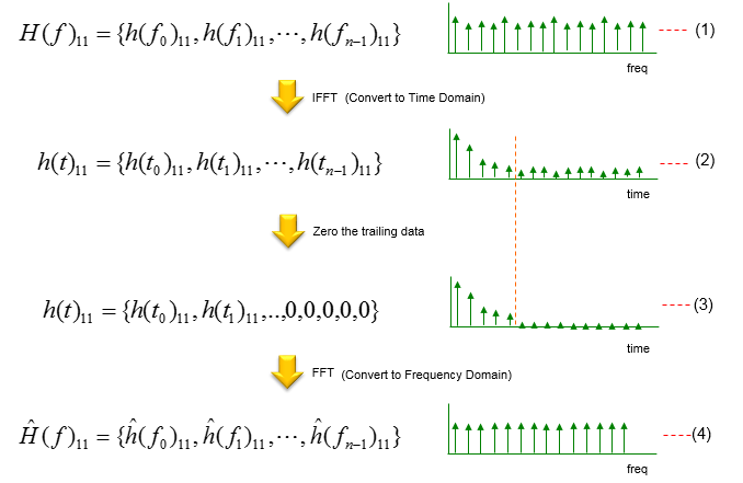
For each of these arrays, I will do the same processing as illustrated below. (Each chipset maker may apply apply a little bit different method, but overall idea would be similar). In the method illustrated below, the data (the array of channel coefficient in each frequency points) is applied with IFFT, meaning the dta is converted into a time domain resulting in an array of time domain data labeled as (2). Actually this is a impulse response of the specific channel path. And then we apply a specific filtering (or windowing) to this time domain data. In this example, replace the data from a certain point with zero and creating the result labeled as (3). You may apply a more sophisticated filter or windowing instead of this kind of simple zeroing. And then, by converting the filtered channel impulse data back to frequency domain, I get the filtered channel coefficient and I use that value as 'Estimated channel coefficient' in the processing of decoding other recieved signal (i.e, decoding non-reference data).
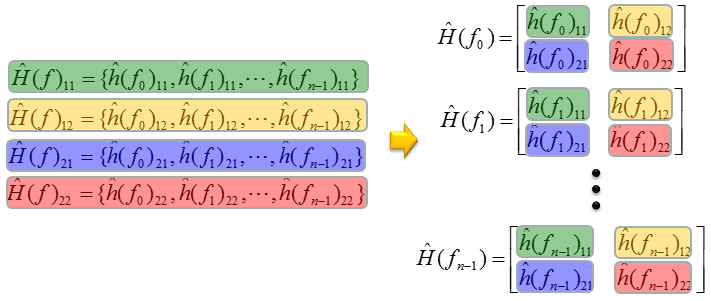
By doing the same process to all the four array, you get the four arrays of 'Estimated Channel Coefficient Array'. From these four arrays, you can reconstructed the array of estimated channel matrix as follows.
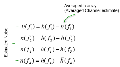
With this estimated channel matrix, you can estimate the noise values at each point using the following equation. This is same as original system equation at the beginning of this page except that H matrix is replaced by 'Estimated H' matrix and now we know all the values except noise value. So, by plugging in all the know values we can calculate (estimate) noise values at each measurement point.
If you apply this equation for all the measurement point, you would get the noise values for all the measurement point and from those calculated noise value you can get the statistical properties of the noise. As mentioned above, the each individual noise value calculated here does not have much meaning because the value cannot be directly applicable to decoding other signal (non-reference signal), but the statistical characteristics of these noise can be a very useful information to determine the nature of the channel.
NOTE : I strongly recommend to read/try Ref[2] and [3] if you are interested in how this algorithm is being used in real application.
Reference :
[1] srsLTE: \srslte\lib\ch_estimation\chest_dl.c - srslte_chest_dl_estimate_port()
[2] Channel Estimation (Mathworks, LTE Toolbox)
[3] NR Synchronization Procedures
YouTube :
- Wireless Comm. Unit 07. Channel Estimation and Equalization. Sect 1. Introduction - Sundeep Rangan (2021)
- Wireless Comm. Unit 07. Channel Estimation and Equalization. Sect 2. Kernel Regression Estimation - Sundeep Rangan (2021)
- Wireless Comm. Unit 07. Channel Estimation and Equalization. Sect 3. Bias-Variance Tradeoff - Sundeep Rangan (2021)
- Learning-aided channel estimation for 5G NR - Nitin Jonathan Myers (2021)