NOTE : At high level view, it would not be difficult to understand overall concept of CSI. However, getting deeper into the details.. it would become much complicated .. and tooooooooooooo confusing (at least very confusing to me). That is one of the reason why I wrote multiple pages for the same topic (CSI). Multiple pages for the same topic can be additional confusion to some readers (even to me). However, I thought the page would get too big for download if I put everything in single page and I also thought it would not be bad to provide a little bit different aspect for the same topic with multiple post. But as I add more pages (post), I thought it would be good to write a page to provide high level view and help readers combine all those multiple pages that I wrote. Refer to CSI Overview page if you are not familiar with big picture of the CSI report.
CQI stands for Channel Quality Indicator. As the name implies, it is an indicator carrying the information on how good/bad the communication channel quality is. This CQI is for HSDPA. (LTE also has CQI for its own purpose).
CQI is the information that UE sends to the network and practically it implies the following two
i) Current Communication Channel Quality is this-and-that..
ii) I (UE) wants to get the data with this-and-that transport block size, which in turn can be directly converted into throughput
Followings are the topics that I will talk about in this page.
- What would happen if UE send inaccurate CQI ?
- How UE estimate CQI ?
- CQI Value and Expected PDSCH Modulation Scheme
- CQI vs SNR
- Which Physical Channel Carriers CQI Value ?
- Two Important CQI Table
- CQI Report and DRX
- CQI Report and SR
- How Network(eNB) trigger UE to send CSI ?
- How to test CQI ?
- CQI Measurement in Livenetwork
What would happen if UE send inaccurate CQI ?
In HSDPA, the CQI value ranges from 0 ~ 30. 30 indicates the best channel quality and 0,1 indicates the poorest channel quality. Depending which value UE reports, network transmit data with different transport block size. If network gets high CQI value from UE, it transmit the data with larger transport block size and vice versa.
What if network sends a large transport block even though UE reports low CQI, it is highly probable that UE failed to decode it (cause CRC error on UE side) and UE send NACK to network and the network have to retransmit it which in turn cause waste of radio resources.
What if UE report high CQI even when the real channel quality is poor ? In this case, network would send a large transport block size according to the CQI value and it would become highly probable that UE failed to decode it (cause CRC error on UE side) and UE send NACK to network and the network have to retransmit it which in turn cause waste of radio resources.
How UE can measure CQI ? This is the most unclear topic to me. As far as I know, there is no explicit description in any standard on the mechanism by which the CQI is calculated, but it is pretty obvious that the following factors play important roles to CQI measurement.
- signal-to-noise ratio (SNR)
- signal-to-interference plus noise ratio (SINR)
- signal-to-noise plus distortion ratio (SNDR)
It is not defined in the specification on how these factors are used and whether there is any other factors being involved. The implementation is all up to chipset makers. In most case, the chipset maker derives a complicated mathemtical formula called channel model and derive SNR/SINR/SNDR from the channel model. And then, they do a lot of testing to correlate the measured SNR and the measured BLER by the chipset and create some internal table (or equation) for the correlation. And the mapping table(function) would eventually used to determine CQI value.
CQI Value and Expected PDSCH Modulation Scheme
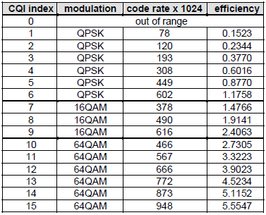
In LTE, there are 15 different CQI values randing from 1 to 15 (4 bits) and mapping between CQI and modulcation scheme, transport block size is defined as follows (36.213)
|
< 36.213 Table 7.2.3-1 > |
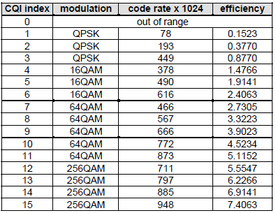
< 36.213 Table 7.2.3-2 > |
|
|
|
If you are an engineer in Network (eNodeB) programming, you need to know the number of resource blocks and MCS for each CQI value to properly allocate the resources for each of UEs. With the modulation scheme in the table, you would get a certain range of MCS you can use for each CQI index. But you cannot pinpoint a specific MCS and Number of RBs. You need another condition to get the proper MCS and N RBs and it is 'Code Rate' shown in the table. But still there is not a single formula that would give you a single/determined value for MCS and NRB. You have to come up with a set of MCS and N RB that meet the modulation scheme and Code Rate requirement in the table. One example case can be as follows.
|
CQI |
Modulation |
Bits/Symbol |
REs/PRB |
N_RB |
MCS |
TBS |
Code Rate |
|
1 |
QPSK |
2 |
138 |
20 |
0 |
536 |
0.101449 |
|
2 |
QPSK |
2 |
138 |
20 |
0 |
536 |
0.101449 |
|
3 |
QPSK |
2 |
138 |
20 |
2 |
872 |
0.162319 |
|
4 |
QPSK |
2 |
138 |
20 |
5 |
1736 |
0.318841 |
|
5 |
QPSK |
2 |
138 |
20 |
7 |
2417 |
0.442210 |
|
6 |
QPSK |
2 |
138 |
20 |
9 |
3112 |
0.568116 |
|
7 |
16QAM |
4 |
138 |
20 |
12 |
4008 |
0.365217 |
|
8 |
16QAM |
4 |
138 |
20 |
14 |
5160 |
0.469565 |
|
9 |
16QAM |
4 |
138 |
20 |
16 |
6200 |
0.563768 |
|
10 |
64QAM |
6 |
138 |
20 |
20 |
7992 |
0.484058 |
|
11 |
64QAM |
6 |
138 |
20 |
23 |
9912 |
0.600000 |
|
12 |
64QAM |
6 |
138 |
20 |
25 |
11448 |
0.692754 |
|
13 |
64QAM |
6 |
138 |
20 |
27 |
12576 |
0.760870 |
|
14 |
64QAM |
6 |
138 |
20 |
28 |
14688 |
0.888406 |
|
15 |
64QAM |
6 |
138 |
20 |
28 |
14688 |
0.888406 |
Note 1 : Refer to Throughtput Calculation Example for determining N_RB, MCS, TBS determination.
Note 2 : REs/PRB varies depending on CFI value as follows.
|
CFI |
REs/PRB |
|
1 |
150 |
|
2 |
138 |
|
3 |
126 |
Note 3 : I used the following formula explained in Code Rate section.
v_CodingRate := (int2float(p_TBSize + 24)) / (int2float(p_N_PRB * tsc_REs_Per_PRB * v_BitsPerSymbol));
As mentioned earlier, the main criteria for UE to determined CQI value is SNR, but the exact mapping between the measured SNR and CQI may vary a little depending on each modem manufacturer, but overall correlation between CQI and SNR would be similar. Every modem manufacturer would keep their own mapping table in their physical layer protocol stack but in most case the venders would not open those tables in public. Fortunally, I found a data from Ref [3] as follows. This example would give you a concrete insight about CQI determination.
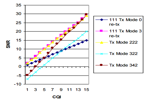
Following is the description of each of the traces shown in the graph.
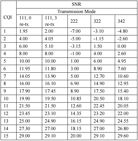
- 111 Tx Mode 0 re-tx:TM1, Number of Tx Antenna = 1, Number of Rx Antenna = 1, HARQ Max retransmission = 0
- 111 Tx Mode 3 re-tx:TM1, Number of Tx Antenna = 1, Number of Rx Antenna = 1, HARQ Max retransmission = 3
- 222 Tx Mode:TM2, Number of Tx Antenna = 2, Number of Rx Antenna = 2
- 322 Tx ModeTM3, Number of Tx Antenna = 2, Number of Rx Antenna = 2
- 342 Tx Mode:TM3, Number of Tx Antenna = 4, Number of Rx Antenna = 2
Following is the same data as shown in the above graph, but summarized in tabular format.
Which Physical Channel Carriers CQI Value ?
CQI is carried by PUCCH or PUSCH depending on the situation as follows.
- Carried by PUCCH : Periodic CQI
- Carried by PUSCH : Aperiodic CQI (and Periodic CQI)
Regarding CQI report period and configuration, refer to CQI, PMI, RI Reporting Configuration part.
We have two different tables as shown below defined in 36.213. Now the question is in which situation the first table (Table 7.2.3-1) is used and in which situation the second table(Table 7.2-1) is used). Overall story is described in 36.213 section 7.2, I will just re-organize those statements in a little bit different structure.
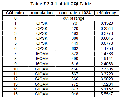
The table shown above is used in following situation. In this table, 4 bit is used to indicate each CQI value.
1) For transmission modes 1, 2, 3 and 5, as well as transmission modes 8, 9 and 10 without PMI/RI reporting, transmission mode 4 with RI=1, and transmission modes 8, 9 and 10 with PMI/RI reporting and RI=1
2) For RI > 1 with transmission mode 4, as well as transmission modes 8, 9 and 10 with PMI/RI reporting, PUSCH based triggered reporting. In this case, one out of the 4 bit CQI (16 different value) is reported for each Codeword (CW0 and CW1).
Following is another table that is used for CQI report, but this is not the absolute value. It is a different value for two different CQI value. Then.. how this difference is defined ? It is defined as follows :
Codeword 1 offset level = wideband CQI index for codeword 0 – wideband CQI index for codeword 1.
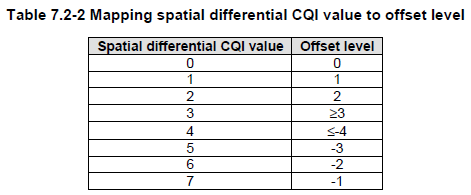
This table is used in following case :
1) For RI > 1 with transmission mode 4, as well as transmission modes 8, 9 and 10 with PMI/RI reporting, PUCCH based reporting includes reporting a 4-bit wideband CQI for codeword 0 according to Table 7.2.3-1 and a wideband spatial differential CQI
When you configure/enable CQI report, you need to take into consideration of other type of periodic acitivties that might be happening in UE. The most typicial type of periodic activities you have to consider is DRX(C-DRX : Connected Mode DRX).
There are a couple of points in 3GPP specification that you may refer to are as follows :
36.321 V11.5.0-5.7 Discontinuous Reception (DRX) states as follows :
if CQI masking (cqi-Mask) is setup by upper layers:
in current subframe n, if onDurationTimer would not be running considering grants/assignments/DRX Command MAC control elements received until and including subframe n-5 when evaluating all DRX Active Time conditions as specified in this subclause, CQI/PMI/RI/PTI on PUCCH shall not be reported.
- else:
in current subframe n, if the UE would not be in Active Time considering grants/assignments/DRX Command MAC control elements received and Scheduling Request sent until and including subframe n-5 when evaluating all DRX Active Time conditions as specified in this subclause, CQI/PMI/RI/PTI on PUCCH shall not be reported.
Simply put, this means 'If CDRX is eanbled and UE is in sleeping mode due to CDRX acitivity, UE shall not send CSI(CQI /PMI /RI).
Since CQI (especially periodic CQI) is carried by PUCCH, you need to consider another information that is carried by PUCCH. One important case you need to take into account is SR (Scheduling Request).
36.213 V12.7.0 - 7.2.2 Periodic CSI Reporting using PUCCH states as follows :
If the UE is not configured for simultaneous PUSCH and PUCCH transmission or, if the UE is configured for simultaneous PUSCH and PUCCH transmission and not transmitting PUSCH, in case of collision between CSI and positive SR in a same subframe, CSI is dropped.
It means .. if there is a case where UE needs to send both SR and CQI, SR transmission has higher priority and CQI gets dropped.
How Network(eNB) trigger UE to send CSI ?
I hope you got the general picture of CQI by now. Now a question that comes to your mind would be how the network trigger UE to send CQI (in other words, when UE is supposed to send CSI. CQI is a kind of CSI. So I would explain on triggering CSI here).
There are roughly two types of CQI triggering mechanism (i.e, Periodic and Aperiodic) and the detailed procedure are a little bit different between these two types.
- Periodic Report : In this mode, UE is supposed to send CQI report periodically with a specified interval. The interval and specific subframe a UE is supposed to send the report is specified in RRC message. (Refer to CQI, PMI, RI Reporting Configuation-Details on Periodic Report for the details).
- Aperiodic Report : In this mode, UE is supposed to send CSI report only when it gets a specific trigger from the network. What do you mean by 'specific trigger' ? It means 'CSI Request field in DCI 0'. It means the direct trigger for Aperiodic CSI is DCI 0(UL Grant). However, this direct trigger is not enough for the UE. UE has to know what kind of CSI it should report (e.g, CQI only ? CQI and PMI ? CQI and PMI and RI ?). what about the case of carrier aggregation ? Do I (UE) have to report for PCC ? or SCC? or both PCC and SCC ? All of these detailed informations is configured by RRC message(Refer to CQI, PMI, RI Reporting Configuation-Details on Aperiodic Report and CQI/RI Feedback type for the details)
How can we test CQI report functionality ? There are roughly two different types of test method. (The word 'type' is my personal expression.. it is not 3GPP term. Don't try to look for 'CQI test Type 1' or 'Type 2' in 3GPP document :)
< Type 1 : Live Network Behavior Test >
The first type may not be an accurate test for UE's CQI report functionality, but it is closer to live network behavior. Overall sequence of CQI report and eNB reaction to the report is as follows :
- i) UE sends a CQI report with a certain value (e.g, 15)
- ii) eNB sends PDSCH with the highest MCS (i.e, the highest code rate and the largest transport block)
- iii) If UE can successfully decode it (meaning BLER lower than a certain limit), it sends the same or higher CQI.
- iv) eNB sends PDSCH with the lower MCS(i.e, the lower code rate and the smaller transport block)
- v) go to step iii)
If UE fail to decode it(meaning BLER higher than a certain limit), it sends the CQI less than the previous one
With this procedure, eNB can transmit PDSCH with the code rate (MCS) that can be successfully decoded by UE (i.e, causing no CRC/no BLER).
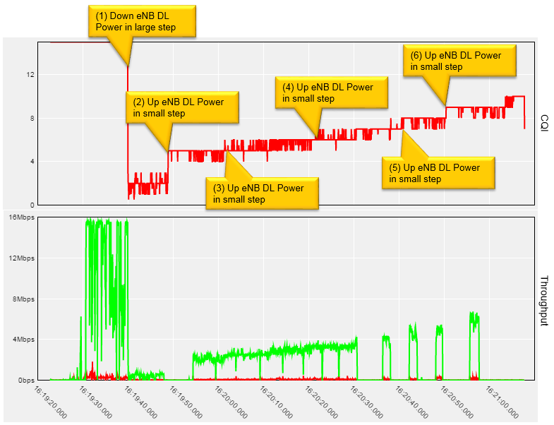
Following is one example of CQI report and throughput change based on Radio Channel Quality between a UE and LTE Network Simulator from Amarisoft. It configures CQI configuration as follows by default. (If you are not familiar with the meaning of these parameters, refer to CQI Report Configuration page)
cqi-ReportConfig {
nomPDSCH-RS-EPRE-Offset 0,
cqi-ReportPeriodic setup: {
cqi-PUCCH-ResourceIndex 0,
cqi-pmi-ConfigIndex 38,
cqi-FormatIndicatorPeriodic widebandCQI: NULL,
simultaneousAckNackAndCQI FALSE
}
},
First I get UE camped on the LTE Simulator with a good radio channel and start downloading YouTube from the UE. While UE is downloading YouTube video, I changed cell power (Downlink Power) step by step. The upper plot is cell power change and the average CQI (Average of 50 subframes) in reaction to the cell power change and lower plot shows the throughput change in accordance to CQI changes. This throughput change is because eNB assigns different MCS in response to CQI report. Amarisoft WebInterface Logging/Analysis tool allow us to get this kind of graph with a couple of button click.
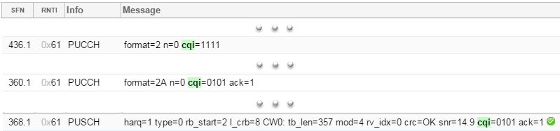
CQI report is carried by different channels (PUCCH or PUSCH) and in different format (e.g, PUCCH format 2 or 2A etc) depending on situation. Amarisoft logging captures all the PUCCH and PUSCH information as shown below.
< Type 2 : RF Conformance Test : CQI Measurement Accuracy Test >
Another type of CQI testing can be more accurate test for UE's CQI report capability (but you wouldn't see this kind of behavior in live network). Briefly speaking the overall procedure is as follows.
- i) eNB sends a PDSCH with the condition for a certain CQI (e.g, CQI 8)
- ii) UE sends a CQI report with a certain value (e.g, CQI 6)
- iii) (if it is live network, eNB would send PDSCH with MCS corresponding to CQI 6, but) eNB sends PDSCH with the same CQI (same MCS) regardless of the CQI value from UE.
- iv) Repeat this process many times (e.g, 2000 times) and calculate statistical distribution plot (e.g, histogram) using the CQI values from UE.
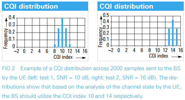
More accurately, you may refer to the test procedure described in 3GPP 36.521. Chapter 9 of 36.521-1 is all about CQI report test. There are many test cases in the chapter but test procedure are similar for all the test cases. They do the similar procedure with various different channel condition. A most typical procedure is described as below.
36.521-1 9.2.1.1.4.2 Test procedure
The SS shall transmit PDSCH via PDCCH DCI format 1A for C_RNTI to transmit the DL RMC according to CQI value 8 and keep it regardless of the wideband CQI value sent by the UE. The SS sends downlink MAC padding bits on the DL RMC. Continue transmission of the PDSCH until 2000 wideband CQI reports have been gathered. In this process the SS collects wideband CQI reports every 5 ms and also cases where UE transmits nothing in its CQI timing are also counted as wideband CQI reports.
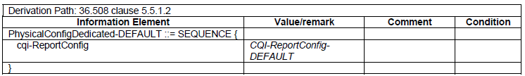
< 36.521-1 Table 9.2.1.1.4.3-1: PhysicalConfigDedicated-DEFAULT >
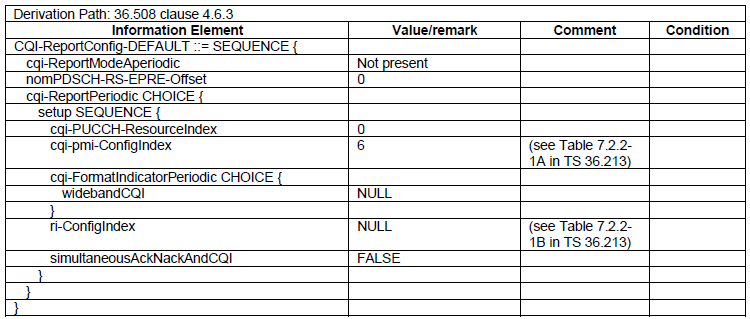
< 36.521-1 Table 9.2.1.1.4.3-2: CQI-ReportConfig-DEFAULT >
Main purpose of this test is to check the accuracy of UE's CQI report (i.e, to check how accurantely UE estimate the radio channel condition and send the corresponding CQI report). Following is an example of test results shown in Reference 2.
CQI Measurement in Livenetwork
The final goal of designing the concept of CQI and implementing it in such a complicated (confusing way) is to achieve the least amount of error and the best possible rate of throughput. There are many factors influencing the throughput and each of the factors would have some kind of correlations with other factors. In Lab test, it is relatively easy to figure out those correlations since you can control those factors (parameters) as fitting the best for analysis, but in live network it is not always that easy to figure out those correlations because most of those factors (parameters) changes dynamically. So the livenetwork test result would not be easily explainable but I think it always good to have some level of experience with livenetwork test result.
General rule of thumb for the correlation between CQI and throughput can be summarized as follows.
- i) High throughput does not necessarily mean high CQI. (High throughput depends not only on CQI, but also on transport block size (Number of RB and MCS. Even when CQI is high, eNB may assign small resources due to various other factors)
- ii) Low throughput does not necessarily mean low CQI. (The reason is same as above)
- iii) With low CQI, it is for sure that you cannot achieve the maximum throughput. So, it is very likely that you would see low CQI when you see throughput drop in livenetwork test.
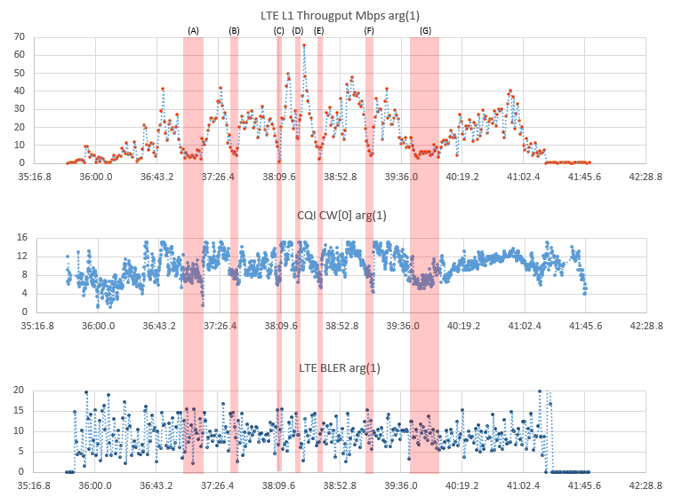
Example 1 > Throughput, CQI, BLER while driving on a highway
Following plot is from the data captured by a drive test tool Azenqos Drive Test tool (AZQ Android). I got the log captured by the tool and exported the data as csv file and then plot it on Microsoft Excel. As mentioned above, you would not get always high throughput whever you have high CQI, but it is very likely to see low CQI when you see throughput dips (drops) as marked in shaded box.
One thing I notice from this specific example is that BLER is a little bit higher than I expected. As mentioned above, one of the main goal of CQI design/implementation is to minimize the BLER, but I think the BLER in this log seems to be a little bit too high. If this result is only for a specific UE, it might be the UE issue. However, this kind of result is observed for most of the UE tested in that area, it would be good to optimize the network parameters for that area.
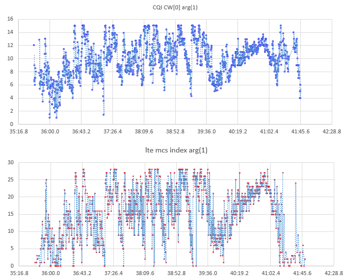
Example 2 > CQI vs MCS
Following plot is from the data captured by a drive test tool Azenqos Drive Test tool (AZQ Android). I got the log captured by the tool and exported the data as csv file and then plot it on Microsoft Excel.
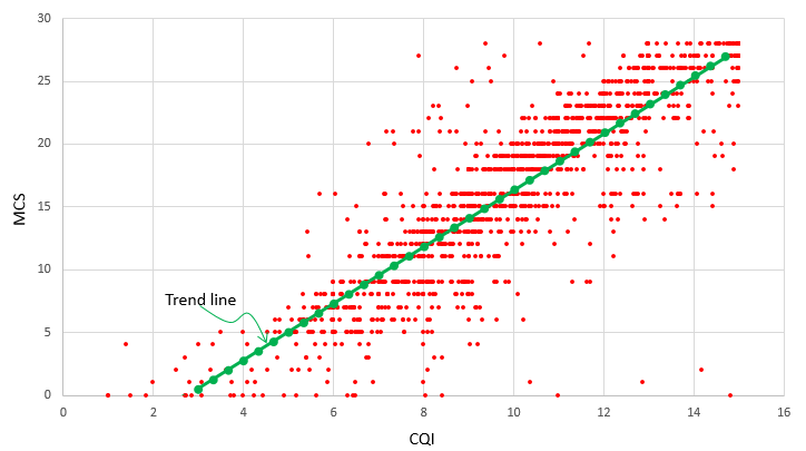
Even in live network measurement, you may see pretty obvious correlation between CQI and MCS. This should be relatively obvious because network changes MCS dynamically based on CQI to minimize the MCS.
The correlation between CQI and MCS would be more obvious if you plot the data in a scatter plot as shown below. Even though the data points are scattered around you may say it is relatively well aligned along a straight line (the green line). Of course it would be better to have those points spread less.
Reference
[1] LTE Channel State Information (CSI) - Keysight
[2] R&S®TS8980 test system analyzes LTE quality indicators: CQI, PMI and RI
[3] Downlink SNR to CQI Mapping for Different Multiple Antenna Techniques in LTE by Mohammad T. Kawser et al.