As of Mar 2028, 38.321 (MAC Specification) is almost completed and of course it is evolving continuously evolving. In this page, I will describe on NR MAC and try to explain in the comparison to LTE MAC whenever it is possible. If you are familiar with LTE MAC, this comparison would help you a lot to understand NR MaC.
- High Level View of NR MAC Layer
- Channel Mapping at MAC Layer
- Comparison of MAC PDU / Headers between NR and LTE
- NR MAC Subheader Structure
- NR MAC Subheader Decoding Examples
- Example 1 : R/F/LCID/L Subheader With 8 Bit L Field
- Example 2 : R/F/LCID/L Subheader With 16 Bit L Field
- Example 3 : R/LCID Subheader Without L Field
- Example 4 : LCID 56 Duplication Activation/Deactivation
- Example 5 : LCID 57 SCell Activation/Deactivation Four Octets
- Example 6 : LCID 58 SCell Activation/Deactivation One Octet
- Example 7 : LCID 61 Timing Advance Command
- Example 8 : LCID 62 UE Contention Resolution Identity
- Example 9 : LCID 63 Padding
- NR MAC Subheader Decoding Examples
High Level View of NR MAC Layer
High level MAC functionality and its interaction with lower and higher layer can be summarized as in the following diagram.
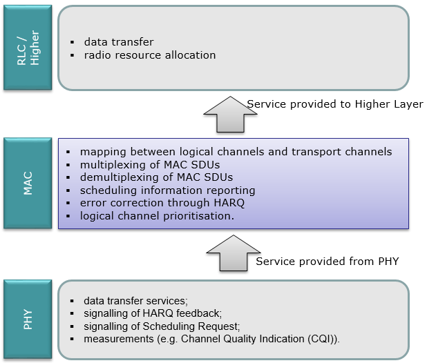
At high level view, NR MAC function/operation is very similar to LTE MAC function/operation. For your reference, I put the NR MAC function and LTE MAC function side-by-side as below.
|
5G/NR(38.321) |
LTE(36.321) |
|
|
Services provided to upper layers |
|
|
|
MAC Functions |
|
|
|
Services expected from physical layer |
|
|
There is another way of describing MAC functionality. It is to describe about each separate procedures that are performed by MAC as summarized below. This is the way I like to describe MAC layer. When MAC and PHY layer specification gets finalized, I would create separate pages for each of these process.
|
Procedure Name |
Description |
| Random Access Procedure | Get the initial uplink grant and perform synchronization to network |
| DL-SCH data transfer (NW) | Do everything needed to perform DL Data Transfer (DCI-Scheduling, HARQ etc) |
| UL-SCH data scheduling (NW) | Schedule UL data transmission by sending DCI X (UL Grant) |
| UL-SCH data transfer (UE) | Do everything needed to perform UL Data Transfer (DCI X decoding, HARQ, multiplexing and assembly) |
| SR-Scheduling Request (UE) | Send the request to Network to get a UL Grant |
| DRX - Discontinous Reception | Control UE's PDCCH monitoring activity in special pattern mainly to save energy consumption |
| SPS - Semi Persisent Scheduling | Scheduling DL/UL transmission in special pattern to reduce scheduling overhead |
| PCH Reception | Monitoring Paging message in special period |
| BCH Reception | Get basic information on cell (MIB and SFN) |
Channel Mapping at MAC Layer
The illustration shown above may show you a little bit detailed picture of MAC process, but it may not be so clear about the channel mapping unless you follow through each lines very carefully. In terms of channel mapping, the tables in 38.321 would be clearer and simple to understand and my illustration to the right would be even more clear and intuitive :).
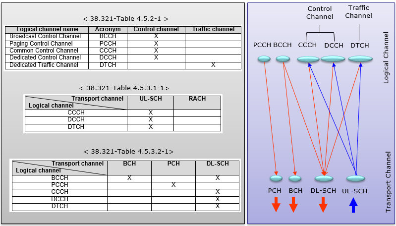
As you see, most of channels from Logical channel to Transport channel is one-to-one or many-to-one relation, but BCCH case it maps to BCH and DL-SCH.
What does this mean ? Does this mean that a BCCH message maps both to BCH and DL-SCH simultaneously ?
No. It means some BCCH data maps to BCH and some BCCH data maps to DL-SCH. If you are familiar with LTE, you would know there are largely two types of BCCH in LTE. One is MIB and the others are SIBs. MIB goes through BCCH-BCH path and SIBs go through BCCH-DL SCH path. NR would use the same pattern of channel mapping.
Refer to Channel Mapping page to see how this mapping embedded into the mapping with wider scope.
Comparison of MAC PDU / Headers between NR and LTE
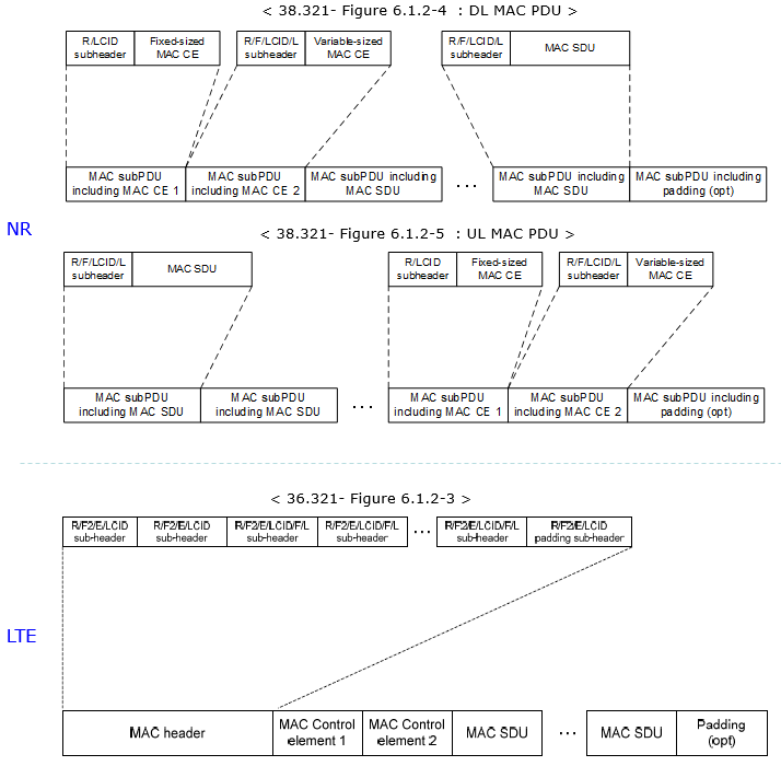
Following shows the overal MAC PDU struction of NR and LTE MAC. You would notice here, all the MAC subhaeders are located at the beginning of a MAC PDU in LTE, but in NR MAC subheaders are located right in front of corresponding SDU(Payload). In other words, in LTE MAC Subheader and correponding data are located in different region, but in NR MAC subheader and corresponding data(payload) are in the same region sitting next to each other.
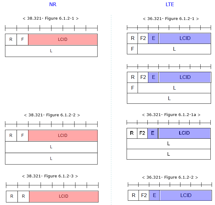
Followings shows header structure of MAC subheaders in NR and LTE. Overall structure would look similar but in NR there is no 'E' field. NR does not require 'E' field since one subheader is located right in front of the corresponding payload. There is no case where multiple headers are sitting next to each other. So 'E' filed is not needed (NOTE : 'E' field indicate whether any other MAC header come after the current MAC subheader).
NR MAC Subheader Structure
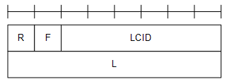
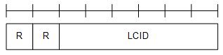
Followings shows the structure of MAC Subheaders in NR and meaning of each field in the sub headers.
< 38.321- Figure 6.1.2-1 R/F/LCID/L MAC subheader with 8-bit L field >
< 38.321- Figure 6.1.2-2 R/F/LCID/L MAC subheader with 16-bit L field >

< 38.321- Figure 6.1.2-3 R/LCID MAC subheader >
|
Field |
Description |
|
LCID |
This field indicates Logical Channel ID. There is one LCID field per MAC subheader. The LCID field size is 6 bits; |
|
L |
This indicates Length of the corresponding MAC SDU or variable-sized MAC CE in bytes. There is one L field per MAC subheader except for subheaders corresponding to fixed-sized MAC CEs and padding. The size of the L field is indicated by the F field; |
|
F |
F stands for 'Format'. It indicates the size of the Length field. There is one F field per MAC subheader except for subheaders corresponding to fixed-sized MAC CEs and padding. The size of the F field is 1 bit.
|
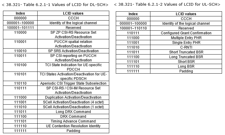
Followings table shows the LCID field in MAC Subheader based on 38.321 v15.1 (Mar 2018 version).
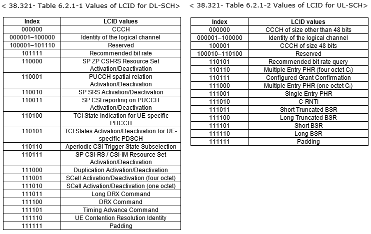
Followings table shows the LCID field in MAC Subheader based on 38.321 v15.2 (Jun 2018 version).
Comparing to v15.1, followings are added or modified.
- DL : Recommended bit rate is added
- UL : CCCH is divided into two different types, CCCH of size other than 48bits and CCCH of size of 48 bits
Followings table shows the LCID field in MAC Subheader based on 38.321 v16.4 (Apr 2021 version).

Followings table shows the LCID field in MAC Subheader based on 38.321 v19.0 (Oct 2025 version).
< 38.321 - Table 6.2.1-1: Values of LCID for DL-SCH >
|
Codepoint/Index |
LCID values |
|---|---|
|
0 |
CCCH |
|
1–32 |
Identity of the logical channel of DCCH, DTCH and multicast MTCH |
|
33 |
Extended logical channel ID field (two-octet eLCID field) |
|
34 |
Extended logical channel ID field (one-octet eLCID field) |
|
35–46 |
Reserved |
|
47 |
Recommended bit rate |
|
48 |
SP ZP CSI-RS Resource Set Activation/Deactivation |
|
49 |
PUCCH spatial relation Activation/Deactivation |
|
50 |
SP SRS Activation/Deactivation |
|
51 |
SP CSI reporting on PUCCH Activation/Deactivation |
|
52 |
TCI State Indication for UE-specific PDCCH |
|
53 |
TCI States Activation/Deactivation for UE-specific PDSCH |
|
54 |
Aperiodic CSI Trigger State Subselection |
|
55 |
SP CSI-RS/CSI-IM Resource Set Activation/Deactivation |
|
56 |
Duplication Activation/Deactivation |
|
57 |
SCell Activation/Deactivation (four octets) |
|
58 |
SCell Activation/Deactivation (one octet) |
|
59 |
Long DRX Command |
|
60 |
DRX Command |
|
61 |
Timing Advance Command |
|
62 |
UE Contention Resolution Identity |
|
63 |
Padding |
< 38.321 - Table 6.2.1-1a: Values of two-octet eLCID for DL-SCH >
|
Codepoint |
Index |
LCID values |
|---|---|---|
|
0 to (216 − 1) |
320 to (216 + 319) |
Identity of the logical channel |
< 38.321 - Table 6.2.1-1b: Values of one-octet eLCID for DL-SCH >
|
Codepoint |
Index |
LCID values |
|---|---|---|
|
0 to 207 |
64 to 271 |
Reserved |
|
208 |
272 |
On-demand SSB Activation/Deactivation (one octet eL field) |
|
209 |
273 |
On-demand SSB Activation/Deactivation (four octet eL field) |
|
210 |
274 |
SP CSI-RS/CSI-IM Resource Set Activation/Deactivation |
|
211 |
275 |
UL Rate Control |
|
212 |
276 |
Pathloss Offset Update |
|
213 |
277 |
SP CSI-RS/CSI-IM Resource Set Activation/Deactivation for Candidate Cell |
|
214 |
278 |
Enhanced LTM Cell Switch Command |
|
215 |
279 |
Aggregated SP Positioning SRS Activation/Deactivation |
|
216 |
280 |
Enhanced SP CSI reporting on PUCCH Activation/Deactivation |
|
217 |
281 |
Cross-RRH TCI State Indication for UE-specific PDCCH |
|
218 |
282 |
LTM Cell Switch Command |
|
219 |
283 |
Candidate Cell TCI States Activation/Deactivation |
|
220 |
284 |
SP SSB Based Beam Indication |
|
221 |
285 |
Activation/Deactivation for Joint TCI States |
|
222 |
286 |
Enhanced Unified TCI states Activation/Deactivation MAC CE for Joint TCI States |
|
223 |
287 |
Enhanced Unified TCI states Activation/Deactivation MAC CE for Separate TCI States |
|
224 |
288 |
NCR Access Link Beam Indication |
|
225 |
289 |
NCR Downlink Backhaul Link Beam Indication |
|
226 |
290 |
NCR Uplink Backhaul Link Beam Indication |
|
227 |
291 |
Serving Cell Set based SRS TCI State Indication |
|
228 |
292 |
SP/IAP SRS TCI State Indication |
|
229 |
293 |
BFD-RS Indication |
|
230 |
294 |
Differential Koffset |
|
231 |
295 |
Enhanced SCell Activation/Deactivation (one octet eL field) |
|
232 |
296 |
Enhanced SCell Activation/Deactivation (four octet eL field) |
|
233 |
297 |
Unified TCI States Activation/Deactivation |
|
234 |
298 |
PUCCH Power Control Set Update for multiple PUCCH repetition |
|
235 |
299 |
PUCCH spatial relation Activation/Deactivation for multiple TRP PUCCH repetition |
|
236 |
300 |
Enhanced TCI States Indication for UE-specific PDCCH |
|
237 |
301 |
Positioning Measurement Gap Activation/Deactivation Command |
|
238 |
302 |
PPW Activation/Deactivation Command |
|
239 |
303 |
DL Tx Power Adjustment |
|
240 |
304 |
Timing Case Indication |
|
241 |
305 |
Child DL-BU Resetting Beam Indication |
|
242 |
306 |
Case-7 Timing advance offset |
|
243 |
307 |
Provided Guard Symbols for Case-6 timing |
|
244 |
308 |
Provided Guard Symbols for Case-7 timing |
|
245 |
309 |
Serving Cell Set based SRS Spatial Relation Indication |
|
246 |
310 |
PUCCH Pathloss Reference RS Update |
|
247 |
311 |
Pathloss Reference RS Update |
|
248 |
312 |
Enhanced SP/IAP SRS Spatial Relation Indication |
|
249 |
313 |
Enhanced PUCCH Spatial Relation Activation/Deactivation |
|
250 |
314 |
Enhanced TCI States Activation/Deactivation for UE-specific PDSCH |
|
251 |
315 |
Duplication RLC Activation/Deactivation |
|
252 |
316 |
Absolute Timing Advance Command |
|
253 |
317 |
SP Positioning SRS Activation/Deactivation |
|
254 |
318 |
Provided Guard Symbols |
|
255 |
319 |
Timing Delta |
< 38.321 - Table 6.2.1-1c: Values of LCID for MBS multicast MCCH and MBS broadcast on DL-SCH >
|
Codepoint/Index |
LCID values |
|---|---|
|
0 |
Broadcast MCCH or multicast MCCH |
|
1–32 |
Identity of the logical channel of broadcast MTCH |
|
33–63 |
Reserved |
< 38.321 - Table 6.2.1-2: Values of LCID for UL-SCH when the LX field is not present or is set to 0 >
|
Codepoint/Index |
LCID values |
|---|---|
|
0 |
CCCH of size 64 bits, except for an (e)RedCap UE |
|
1–32 |
Identity of the logical channel of DCCH and DTCH |
|
33 |
Extended logical channel ID field (two-octet eLCID field) |
|
34 |
Extended logical channel ID field (one-octet eLCID field) |
|
35 |
CCCH of size 48 bits for a RedCap UE |
|
36 |
CCCH of size 64 bits for a RedCap UE |
|
37–42 |
Reserved |
|
43 |
Truncated Enhanced BFR (one octet C) |
|
44 |
Timing Advance Report |
|
45 |
Truncated Sidelink BSR |
|
46 |
Sidelink BSR |
|
47 |
Reserved |
|
48 |
LBT failure (four octets) |
|
49 |
LBT failure (one octet) |
|
50 |
BFR (one octet C) |
|
51 |
Truncated BFR (one octet C) |
|
52 |
CCCH of size 48 bits, except for an (e)RedCap UE |
|
53 |
Recommended bit rate query |
|
54 |
Multiple Entry PHR (four octets C) |
|
55 |
Configured Grant Confirmation |
|
56 |
Multiple Entry PHR (one octet C) |
|
57 |
Single Entry PHR |
|
58 |
C-RNTI |
|
59 |
Short Truncated BSR |
|
60 |
Long Truncated BSR |
|
61 |
Short BSR |
|
62 |
Long BSR |
|
63 |
Padding |
|
NOTE: CCCH of size 48 bits and CCCH of size 64 bits are referred to as CCCH and CCCHH, respectively, in TS 38.331. |
|
< 38.321 - Table 6.2.1-2a: Values of two-octet eLCID for UL-SCH >
| Codepoint | Index |
LCID values |
|---|---|---|
|
0 to (215 − 1) |
320 to (215 + 319) |
Identity of the logical channel |
< 38.321 - Table 6.2.1-2b: Values of one-octet eLCID for UL-SCH >
|
Codepoint |
Index |
LCID values |
|---|---|---|
|
0 to 214 |
64 to 278 |
Reserved |
|
215 |
279 |
Multiple Entry Delay Status Report |
|
216 |
280 |
UL Rate Control |
|
217 |
281 |
Event Triggered L1 Measurement Report |
|
218 |
282 |
Truncated Event Triggered L1 Measurement Report |
|
219 |
283 |
Enhanced Multiple Entry PHR for multiple TRP ST×2P (four octets C) |
|
220 |
284 |
Enhanced Multiple Entry PHR for multiple TRP ST×2P (one octets C) |
|
221 |
285 |
Enhanced Single Entry PHR for multiple TRP ST×2P |
|
222 |
286 |
SL LBT Failure |
|
223 |
287 |
Enhanced Multiple Entry PHR with assumed PUSCH (four octets C) |
|
224 |
288 |
Enhanced Multiple Entry PHR with assumed PUSCH (one octets C) |
|
225 |
289 |
Single Entry PHR with assumed PUSCH |
|
226 |
290 |
SL-PRS Resource Request |
|
227 |
291 |
Refined Long BSR |
|
228 |
292 |
Multiple Entry Delay Status Report |
|
229 |
293 |
Enhanced Multiple Entry PHR for multiple TRP (four octets C) |
|
230 |
294 |
Enhanced Multiple Entry PHR for multiple TRP (one octets C) |
|
231 |
295 |
Enhanced Single Entry PHR for multiple TRP |
|
232 |
296 |
Enhanced Multiple Entry PHR (four octets C) |
|
233 |
297 |
Enhanced Multiple Entry PHR (one octets C) |
|
234 |
298 |
Enhanced Single Entry PHR |
|
235 |
299 |
Enhanced BFR (one octet C) |
|
236 |
300 |
Truncated Enhanced BFR (one octet C) |
|
237 |
301 |
Positioning Measurement Gap Activation/Deactivation Request |
|
238 |
302 |
IAB-MT Recommended Beam Indication |
|
239 |
303 |
Desired IAB-MT PSD range |
|
240 |
304 |
Desired DL Tx Power Adjustment |
|
241 |
305 |
Case-6 Timing Request |
|
242 |
306 |
Desired Guard Symbols for Case 6 timing |
|
243 |
307 |
Desired Guard Symbols for Case 7 timing |
|
244 |
308 |
Extended Short Truncated BSR |
|
245 |
309 |
Extended Long Truncated BSR |
|
246 |
310 |
Extended Short BSR |
|
247 |
311 |
Extended Long BSR |
|
248 |
312 |
Extended Pre-emptive BSR |
|
249 |
313 |
BFR (four octets C) |
|
250 |
314 |
Truncated BFR (four octets C) |
|
251 |
315 |
Multiple Entry Configured Grant Confirmation |
|
252 |
316 |
Single Entry Configured Grant Confirmation |
|
253 |
317 |
Desired Guard Symbols |
|
254 |
318 |
BFR (octets C) |
|
255 |
319 |
Pre-emptive BSR |
< 38.321 - Table 6.2.1-2c: Values of LCID for UL-SCH when the LX field is set to 1 >
|
Codepoint |
Index |
LCID values |
|---|---|---|
|
0 |
(215 + 320) |
CCCH of size 48 bits for an/eRedCap UE |
|
1 |
(215 + 321) |
CCCH of size 64 bits for an/eRedCap UE |
|
2 |
(215 + 322) |
CCCH of size 48 bits for PUCCH repetition of Msg4 HARQ-ACK, except for an (e)RedCap UE |
|
3 |
(215 + 323) |
CCCH of size 64 bits for PUCCH repetition of Msg4 HARQ-ACK, except for an (e)RedCap UE |
|
4 |
(215 + 324) |
CCCH of size 48 bits for PUCCH repetition of Msg4 HARQ-ACK of a RedCap UE |
|
5 |
(215 + 325) |
CCCH of size 64 bits for PUCCH repetition of Msg4 HARQ-ACK of a RedCap UE |
|
6 |
(215 + 326) |
CCCH of size 48 bits for PUCCH repetition of Msg4 HARQ-ACK of an eRedCap UE |
|
7 |
(215 + 327) |
CCCH of size 64 bits for PUCCH repetition of Msg4 HARQ-ACK of an eRedCap UE |
|
8 |
(215 + 328) |
CCCH of size 48 bits for PDSCH repetition of Msg4, except for an (e)RedCap UE |
|
9 |
(215 + 329) |
CCCH of size 64 bits for PDSCH repetition of Msg4, except for an (e)RedCap UE |
|
10 |
(215 + 330) |
CCCH of size 48 bits for PDSCH repetition of Msg4 of a RedCap UE |
|
11 |
(215 + 331) |
CCCH of size 64 bits for PDSCH repetition of Msg4 of a RedCap UE |
|
12 |
(215 + 332) |
CCCH of size 48 bits for PDSCH repetition of Msg4 of an eRedCap UE |
|
13 |
(215 + 333) |
CCCH of size 64 bits for PDSCH repetition of Msg4 of an eRedCap UE |
|
14 |
(215 + 334) |
CCCH of size 48 bits for PUCCH repetition of Msg4 HARQ-ACK and PDSCH repetition of Msg4, except for an (e)RedCap UE |
|
15 |
(215 + 335) |
CCCH of size 64 bits for PUCCH repetition of Msg4 HARQ-ACK and PDSCH repetition of Msg4, except for an (e)RedCap UE |
|
16 |
(215 + 336) |
CCCH of size 48 bits for PUCCH repetition of Msg4 HARQ-ACK and PDSCH repetition of Msg4 of a RedCap UE |
|
17 |
(215 + 337) |
CCCH of size 64 bits for PUCCH repetition of Msg4 HARQ-ACK and PDSCH repetition of Msg4 of a RedCap UE |
|
18 |
(215 + 338) |
CCCH of size 48 bits for PUCCH repetition of Msg4 HARQ-ACK and PDSCH repetition of Msg4 of an eRedCap UE |
|
19 |
(215 + 339) |
CCCH of size 64 bits for PUCCH repetition of Msg4 HARQ-ACK and PDSCH repetition of Msg4 of an eRedCap UE |
|
20 to 63 |
(215 + 340) to (215 + 383) |
Reserved |
|
NOTE 1: The MAC entity may use the code point corresponding to a given feature or feature combination only if network indicates support for the corresponding feature or feature combination. NOTE 2: CCCH of size 48 bits and CCCH of size 64 bits are referred to as CCCH and CCCH1, respectively, in TS 38.331. NOTE 3: For UE capable of PUCCH repetition of Msg4 HARQ-ACK, the MAC entity uses the code points corresponding to PUCCH repetition of Msg4 HARQ-ACK if |
||
NR MAC Subheader Decoding Examples
The following examples show how to decode NR MAC subheader bytes from a hex string. These examples focus only on the MAC subheader itself. After the subheader is decoded, the receiver uses the LCID field to identify the corresponding logical channel, MAC CE or padding type, and uses the L field when present to know how many bytes belong to the following MAC SDU or variable-sized MAC CE.
Color code : R, F, LCID, L
Example 1 : R/F/LCID/L Subheader With 8 Bit L Field
Hex string : 05 20
Binary String : 00000101 00100000
|
Field |
Bits / Bytes |
Value |
Decoding |
|---|---|---|---|
|
R |
bit 1 of octet 1 |
0 |
Reserved bit. In this example it is set to 0. |
|
F |
bit 2 of octet 1 |
0 |
The L field is 8 bits long. |
|
LCID |
bits 3-8 of octet 1 |
000101 = 5 |
LCID 5 identifies the logical channel or MAC CE type by using the applicable LCID table. |
|
L |
octet 2 |
0x20 = 32 |
The corresponding MAC SDU or variable-sized MAC CE is 32 bytes long. |
In this example, the first octet 05 is 00000101 in binary. Since F is 0, only the next one octet is used for the L field, and the payload immediately after this subheader is 32 bytes long.
Example 2 : R/F/LCID/L Subheader With 16 Bit L Field
Hex string : 43 01 2C
Binary String : 01000011 00000001 00101100
|
Field |
Bits / Bytes |
Value |
Decoding |
|---|---|---|---|
|
R |
bit 1 of octet 1 |
0 |
Reserved bit. In this example it is set to 0. |
|
F |
bit 2 of octet 1 |
1 |
The L field is 16 bits long. |
|
LCID |
bits 3-8 of octet 1 |
000011 = 3 |
LCID 3 is interpreted by using the applicable LCID table for the direction and channel type. |
|
L |
octets 2-3 |
0x012C = 300 |
The corresponding MAC SDU or variable-sized MAC CE is 300 bytes long. |
In this example, F is 1, so the receiver reads two octets after the first octet as the L field. The value 01 2C in hex is 300 decimal, so the next 300 bytes belong to the payload associated with this subheader.
Example 3 : R/LCID Subheader Without L Field
Hex string : 3C
Binary String : 00111100
|
Field |
Bits / Bytes |
Value |
Decoding |
|---|---|---|---|
|
R |
bits 1-2 of octet 1 |
00 |
Reserved bits. In this example they are set to 0. |
|
LCID |
bits 3-8 of octet 1 |
111100 = 60 |
The LCID value identifies a fixed-sized MAC CE or padding type according to the applicable LCID table. In this example, LCID 60 indicates DRX Command. |
|
F |
not present |
N/A |
This subheader format does not carry an F field. |
|
L |
not present |
N/A |
The payload size is fixed by the LCID-defined MAC CE type, or no payload follows for padding. |
In this example, the receiver does not read any length field after the first octet. The LCID table tells the receiver how to handle the subheader and whether a fixed-size payload follows.
Example 4 : LCID 56 Duplication Activation/Deactivation
This example shows a fixed-size MAC CE identified by LCID 56. The first byte is the R/LCID subheader and the following byte is an example Duplication Activation/Deactivation payload bitmap. Although the first two bits are 00, they are decoded as R = 00, not R = 0 and F = 0, because LCID 56 identifies a fixed-sized MAC CE.
Hex string : 38 05
Binary String : 00111000 00000101
Field |
Bits / Bytes |
Value |
Decoding |
|---|---|---|---|
R |
bits 1-2 of octet 1 |
00 |
Reserved bits in the R/LCID subheader. |
LCID |
bits 3-8 of octet 1 |
111000 = 56 |
Identifies Duplication Activation/Deactivation MAC CE. |
Payload |
octet 2 |
05 = 00000101 |
Example bitmap with two activation bits set. The exact bit-to-bearer mapping follows the configured duplication mapping. |
From the first byte 38, the receiver decodes R = 00 and LCID = 56. Since this is a fixed-size MAC CE, there is no F or L field; the next byte is interpreted as the Duplication Activation/Deactivation command payload.
Example 5 : LCID 57 SCell Activation/Deactivation Four Octets
This example uses the four-octet SCell Activation/Deactivation MAC CE. A bit value of 1 indicates activation for the corresponding SCell index, and 0 indicates deactivation. The exact C field position follows the SCell Activation/Deactivation MAC CE figure.
Hex string : 39 00 00 00 16
Binary String : 00111001 00000000 00000000 00000000 00010110
Field |
Bits / Bytes |
Value |
Decoding |
|---|---|---|---|
R |
bits 1-2 of octet 1 |
00 |
Reserved bits in the R/LCID subheader. |
LCID |
bits 3-8 of octet 1 |
111001 = 57 |
Identifies SCell Activation/Deactivation MAC CE with four payload octets. |
Payload |
octets 2-5 |
00 00 00 16 |
Example SCell bitmap. Interpreting the last octet as C7 C6 C5 C4 C3 C2 C1 R, C4, C2 and C1 are set to 1, so those SCells are activated and the other represented SCells are deactivated. |
From the subheader byte 39, the receiver identifies LCID 57 and therefore reads the next four octets as the SCell Activation/Deactivation bitmap.
Example 6 : LCID 58 SCell Activation/Deactivation One Octet
This example uses the one-octet SCell Activation/Deactivation MAC CE. It is used when the one-octet activation bitmap is sufficient for the configured SCell set.
Hex string : 3A 2A
Binary String : 00111010 00101010
Field |
Bits / Bytes |
Value |
Decoding |
|---|---|---|---|
R |
bits 1-2 of octet 1 |
00 |
Reserved bits in the R/LCID subheader. |
LCID |
bits 3-8 of octet 1 |
111010 = 58 |
Identifies SCell Activation/Deactivation MAC CE with one payload octet. |
Payload |
octet 2 |
2A = 00101010 |
Example activation bitmap. Interpreting the octet as C7 C6 C5 C4 C3 C2 C1 R, C5, C3 and C1 are set to 1, so those SCells are activated and the other represented SCells are deactivated. |
From the subheader byte 3A, the receiver identifies LCID 58 and interprets the next one octet as the SCell activation bitmap.
Example 7 : LCID 61 Timing Advance Command
This example decodes a Timing Advance Command MAC CE. The payload contains TAG ID and Timing Advance Command fields.
Hex string : 3D 55
Binary String : 00111101 01010101
Field |
Bits / Bytes |
Value |
Decoding |
|---|---|---|---|
R |
bits 1-2 of octet 1 |
00 |
Reserved bits in the R/LCID subheader. |
LCID |
bits 3-8 of octet 1 |
111101 = 61 |
Identifies Timing Advance Command MAC CE. |
TAG ID |
bits 1-2 of octet 2 |
01 = 1 |
Timing Advance Group ID is 1. |
TA Command |
bits 3-8 of octet 2 |
010101 = 21 |
Timing Advance Command value is 21. |
From the subheader byte 3D, the receiver identifies LCID 61. The next byte 55 is then split into TAG ID = 1 and Timing Advance Command = 21.
Example 8 : LCID 62 UE Contention Resolution Identity
This example decodes the UE Contention Resolution Identity MAC CE. The payload is fixed at 48 bits and contains the UL CCCH SDU, or the first 48 bits of the UL CCCH SDU if it is longer than 48 bits.
Hex string : 3E A1 B2 C3 D4 E5 F6
Binary String : 00111110 10100001 10110010 11000011 11010100 11100101 11110110
Field |
Bits / Bytes |
Value |
Decoding |
|---|---|---|---|
R |
bits 1-2 of octet 1 |
00 |
Reserved bits in the R/LCID subheader. |
LCID |
bits 3-8 of octet 1 |
111110 = 62 |
Identifies UE Contention Resolution Identity MAC CE. |
Payload |
octets 2-7 |
A1 B2 C3 D4 E5 F6 |
48-bit UE Contention Resolution Identity used by the UE to match its transmitted UL CCCH SDU. |
From the subheader byte 3E, the receiver identifies LCID 62 and reads the following six octets as the contention resolution identity.
Example 9 : LCID 63 Padding
This example shows padding at the end of a MAC PDU. Padding is identified by LCID 63 and does not deliver a MAC SDU or MAC CE payload to upper layers.
Hex string : 3F 00 00
Binary String : 00111111 00000000 00000000
Field |
Bits / Bytes |
Value |
Decoding |
|---|---|---|---|
R |
bits 1-2 of octet 1 |
00 |
Reserved bits in the R/LCID subheader. |
LCID |
bits 3-8 of octet 1 |
111111 = 63 |
Identifies Padding. |
Padding bytes |
octets 2-3 |
00 00 |
Example filler bytes. These bytes are ignored by MAC and are not passed to upper layers. |
From the subheader byte 3F, the receiver identifies padding. The remaining bytes in this example are simply filler to align the MAC PDU to the allocated transport block size.
Reference
[1]