The table below is the whole page compressed into one screen. It answers what RACH is for, which two procedures exist, and why a single purpose needs thirteen preamble formats. Everything after it is the long form of one of those rows.
|
5G RACH in Details
RACH stands for Random Access Channel. It is an essential part of wireless communication systems, including 5G(NR), 4G (LTE) and even 3G(WCDMA). It plays a significant role in establishing an initial connection(Initial Access) between a device and a network.
In layman's terms, you can think of RACH as the first point of contact or the front door to the network. When a device, such as your smartphone or laptop, wants to connect to a network for the first time or after a period of inactivity, it uses the RACH to request access to the network.
Initial Access in this context means a sequence of process between UE and gNB(Network) in order for UE to aquire Uplink Synchronization and obtain specified ID for the radio access communication. In more familiar terms, this Initial Access is refered to be 'RACH process'. Depending on the document, the term Initial Access may mean 'Downlink Synchronization + RACH'. But in my case, Initial Access usually refer to RACH process and I wrote a separate page for downlink synchronization.
Even though the detailed parameter is not determined (as of Apr 2017), the overal logic of NR RACH will be very similar to LTE RACH process (Based on TR 38.804 v1.0.0 - Ref [32]). So if you are already familiar with LTE RACH process, it would easily pick up NR RACH process. If you are not familiar with LTE RACH process, I would strongly recommend to go through LTE RACH page and try to get familiar with the procedure.
- Overall Procedure
- Why RACH ?
- When we need RACH (What Triggers RACH) ?
- Two types of RACH : Contention Based and NonContention Based
- Fundamental Difference from LTE RACH
- Preamble Sequence Generation
- Frequency Domain Sequence Generation
- Time Domain Sequence Generation
- Example of Transmission Location in Time Domain
- Example 01 > TDD FR2 RachConfig = 70, SCS = 120 Khz, Format A3
- Example 02 > TDD FR2 RachConfig = 71, SCS = 120 Khz, Format A3
- Example 03 > TDD FR2 RachConfig = 74, SCS = 120 Khz, Format A3
- Example 04 > TDD FR2 RachConfig = 76, SCS = 120 Khz, Format A3
- Example 05 > TDD FR2 RachConfig = 12, SCS = 120 Khz, Format A1
- Example 06 > TDD FR2 RachConfig = 8, SCS = 120 Khz, Format A3
- Example 07 > TDD FR1 RachConfig = 4 , SCS = 15 Khz, Format 0
- Example 08 > TDD FR1 RachConfig = 79, SCS = 30 Khz, Format A1
- Example 09 > TDD FR1 RachConfig = 78, SCS = 30 Khz, Format A1
- Example 10 > TDD FR1 RachConfig = 131, SCS = 30 Khz, Format A3
- Example 11 > TDD FR1 RachConfig = 128, SCS = 30 Khz, Format A3
- Example 12 > TDD FR1 RachConfig = 133, SCS = 30 Khz, Format B1
- Example 13 > TDD FR1 RachConfig = 136, SCS = 30 Khz, Format B1
- Example 14 > TDD FR1 RachConfig = 141, SCS = 30 Khz, Format B1
- Example 15 > TDD FR1 RachConfig = 160, SCS = 30 Khz, Format B4
- Example 16 > TDD FR1 RachConfig = 156, SCS = 30 Khz, Format B4
- Example 17> TDD FR2 RachConfig = 149, SCS = 120 Khz,Format C0
- Impact of Rach Occasion on Scheduling and TDD UL/DL Configuration
- zeroCorrelationZoneConfig and Ncs
- Root Sequence Index
- Long vs Short Sequences
- Preamble Format
- Long Sequence Table
- Short Sequence Table
- Frequency Bandwidth for PRACH Subcarrier Spacing
- PRACH Cell Dimensioning
- Time Domain Structure
- L1 Processing Time Line for PRACH
- Random Access Configuration
- For FR1 and paired spectrum/supplementary uplink (FR1 FDD)
- For FR1 and unpaired spectrum (FR1 TDD)
- For FR2 and unpaired spectrum (FR2 TDD)
- RRC Parameters for RACH Process
- RACH Procedure for Initial Attach
- System Information (for initial attach) or RRC Connection Reconfiguration (for LTE Interplay)
- Msg 1 - PRACH Preamble
- Msg 2 - RAR (PDCCH/PDSCH )
- Msg 3 (PUSCH)
- Msg 4 - Contention Resolution (PDCCH/PDSCH)
- HARQ ACK/NACK for Msg4
- RACH Procedure for LTE-Interworking (ENDC)
- RACH Occasion
- RACH Sequence Example 01 > ENDC - CBRA(Contention Based RACH)
- RACH Sequence Example 02 > ENDC - CBRA(Contention Based RACH)
- RACH Sequence Example 03 > SA - CBRA(Contention Based RACH)
- 2 Step RACH
- Reference - 3GPP
- Reference- General Readings
Overall Procedure
There are several different types of RACH processes and different use cases where each of those different procedures are used. So it would not be easy to describe every types and use case in short. But I think the overall procedure illustrated below can give you a big picture to help you understand almost every cases of RACH procedure. For example, if you are interested in RACH for NSA Setup, [A]+[C]+[D] would be applicable. If you are interested in Contention Based RACH in SAR, [A]+[B]+[C]+[D] would be applicable.
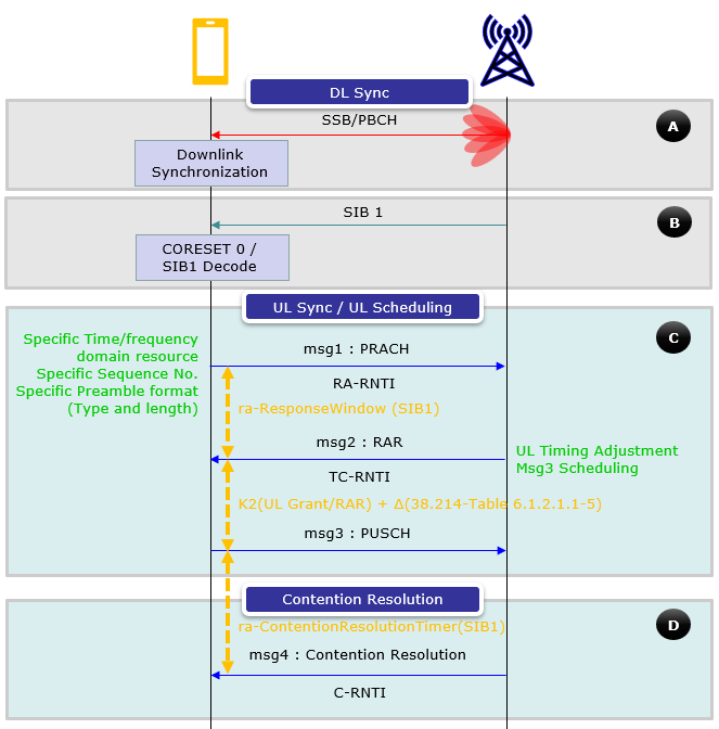
Following is brief description for each step. Full details for each of these steps are pretty compicated and will be explained in other sections of this note.
Why RACH ?
The first question poping up in your mind when you first hear about the word RACH or RACH Process would be 'Why RACH ?', 'What is the functionality/purpose of RACH process ?', "Why we need this kind of complicated (looks over-complicated) ?'.
For sure, it is not for confusing you :), RACH has very important functionality especially in LTE (and in WCDMA as well). The main purpose of RACH can be described as follows.
i) Achieve UP link synchronization between UE and eNB
ii) Obtain the resource for Message 3 (e.g, RRC Connection Request)
In most of the communication (especially digital comunication regardless of whether it is wired or wireless), the most important precondition is to establish the timing synchronization between the reciever and transmitter. So whatever communication technology you would study, you would see some kind of synchronization mechanism that is specially designed for the specific communication.
In NR (in LTE and WCDMA as well), the synchronization in downlink (Transmitter = gNB, Reciever = UE), this synchronization is achieved by the special synchronization channel (special physical signal pattern). Refer to Synchronization page for the details.
This downlink sync signal gets broadcasted to everybody and it is get transmitted all the time with a certain interval.
However in Uplink(Transmitter = UE, Reciever = gNB), it is not efficient (actually waste of energy and causing a lot of interference to other UEs) if UE is using this kind of broadcasting/always-on synchronization mechanism. You may easily understand this kind of problem. In case of uplink, this synchronization process should meet following criteria
i) The synchronization process should happen only when there is immediate necessity
ii) The synchronization should be dedicated to only a specific UE
All the complicated/confusing stories in this page is mostly about the process specially designed mechanism to meet these criteria.
Another purpose of RACH process is to obtain the resource for Msg3 (Message 3). RRC Connection Request is one example of Msg3 and there are several different types of Msg3 depending on situation. You would figure out this part in reading through this page and this is not very complicated to understand.
When we need RACH ?
There are many situation that triggers RACH process. The list of cases are summarized in 38.300-9.2.6 as follows. The first half of the list(i~iv) is same as in LTE case. The second half of the list would be NR specific. We don't have RRC_INACTIVE state (item v), On-Demand SIB transmition(item vii) in LTE, we have a primitive types of BeamFormaing / BeamManagement in LTE but not as sophisticated as in NR(item viii). We do have CA(SCell addition) in LTE but we don't trigger RACH in any of CA activity in LTE(item vi).
i) Initial access from RRC_IDLE;
ii) RRC Connection Re-establishment procedure;
iii) Handover;
iv) DL or UL data arrival during RRC_CONNECTED when UL synchronisation status is "non-synchronised";
v) Transition from RRC_INACTIVE;
vi) To establish time alignment at SCell addition;
vii) Request for Other SI
viii) Beam failure recovery.
Every trigger is a synchronisation problem : the UE either has no uplink timing yet, or has lost confidence in the timing it had. RACH is the only procedure that establishes it from nothing.Two of the triggers are not about the UE at all : a handover and an SCell addition start from a network decision. The UE runs RACH because it was told to, not because it noticed something.Beam failure recovery is the trigger NR added : LTE had no equivalent, because LTE had no narrow beams to lose.The trigger decides the procedure : a network initiated case can hand the UE a dedicated preamble, which is what makes it contention free. A UE initiated case cannot.
Two types of RACH Procedure : Contention Based and NonContention Based
There are largely two types of RACH procedure in terms of allowable physical resources of PRACH (i.e, time and frequency location of PRACH) and sequence index of the PRACH. This is also almost same as in LTE.
Contention based RACH Procedure
When a UE transmit a PRACH Preamble, it transmits with a specific pattern and this specific pattern is called a "Signature". In each LTE cell, total 64 preamble signatures are available and UE select randomly one of these signatures.
UE select "Randomly" one of these signatures ?
Does this mean that there is some possibility that multiple UEs send PRACH with identical signatures ?
Yes.
There is such a possibility. It means the same PRACH preamble from multipe UE reaches the NW at the same time.. this kind of PRACH collision is called "Contention" and the RACH process that allows this type of "Contention" is called "Contention based" RACH Process. In this kind of contention based RACH process, Network would go through additional process at later step to resolve these contention and this process is called "Contention Resolution" step.
Typical 'Contention Based' RACH Procedure is as follows : (Typically 4 steps)
i) UE --> NW : RACH Preamble (RA-RNTI, indication for L2/L3 message size)
ii) UE <-- NW : Random Access Response (Timing Advance, T_C-RNTI, UL grant for L2/L3 message)
iii) UE --> NW : L2/L3 message
iv) Message for early contention resolution
Now let's assume that a contention happened at step i). For example, two UEs sent PRACH. In this case, both of the UE will recieve the same T_C-RNTI and resource allocation at step ii). And as a result, both UE would send L2/L3 message through the same resource allocation(meaning with the same time/frequency location) to NW at step iii). What would happen when both UE transmit the exact same information on the exact same time/frequency location ? One possibility is that these two signal act as interference to each other and NW decode neither of them. In this case, none of the UE would have any response (HARQ ACK) from NW and they all think that RACH process has failed and go back to step i). The other possibility would be that NW could successfully decode the message from only one UE and failed to decode it from the other UE. In this case, the UE with the successful L2/L3 decoding on NW side will get the HARQ ACK from Network. This HARQ ACK process for step iii) message is called "contention resolution" process.
This process can be summarized as below
- In this procedure, multiple UEs can choose the same random access preamble and send it to the base station (eNodeB in LTE or gNodeB in 5G).
- Since multiple UEs might choose the same preamble, there's a possibility of "contention" or collision.
- After sending the preamble, the UEs wait for a response from the base station. If they receive a valid response, they proceed to send additional information to resolve the contention.
- The network then confirms the successful access of one of the contending UEs using a unique identifier (e.g., C-RNTI). UEs that do not receive confirmation know that there was a collision, and they initiate a backoff procedure before trying again.
- This method is typically used for initial access, when the UE is not synchronized with the network or when the network does not have prior scheduling information about the UE.
Non-Contention Based (Contention Free) RACH Procedure
But there is some cases that these kind of contention is not acceptable due to some reason (e.g, timing restriction) and these contention can be prevented. Usually in this case, the Network informs each of the UE of exactly when and which preamble signature it has to use. Of course, in this case Network will allocate these preamble signature so that it would not collide. This kind of RACH process is called "Contention Free" or "Non-Contention based RACH" procedure. To initiate the "Contention Free" RACH process, UE should be in Connected Mode before the RACH process as in Handover case.
Typical 'Contention Free' RACH Procedure is as follows : (Typically 2 steps)
i) UE <--NW : RACH Preamble (PRACH) Assignment (This is done by RRC Configuration, not exactly part of RACH Proc)
ii) UE --> NW : RACH Preamble (RA-RNTI, indication for L2/L3 message size)
iii) UE <--NW : Random Access Response (Timing Advance, C-RNTI, UL grant for L2/L3 message)
This process can be summarized as below
- In this procedure, the network provides dedicated random access resources to specific UEs, ensuring that there's no contention or collision.
- The UE uses the dedicated preamble provided by the network to initiate the RACH procedure.
- Since the resources are dedicated, there's no need for a contention resolution process.
- This method is typically used in scenarios where the network has prior knowledge about the UE's intention to initiate communication. For example, it can be used for handover procedures or when the network anticipates uplink data transmission from the UE based on downlink data or signaling.
Fundamental Difference from LTE RACH
As I mentioned above, the overall protocol sequence would be almost same in LTE and NR, but there are a few differences between the two as summarized below.
- The major difference between LTE RACH and NR RACH would lie just before RACH Preamble gets transmitted. It is due to BeamForming which would be supported by default (especially in mmWave) in NR. So in case when NR is operating in Beamforming mode, UE need to detect and select a best beam for RACH process. This beam selection process would be the fundamental difference between LTE RACH and NR RACH process.
- There are much diverse preample format in 5G/NR comparing to LTE. In LTE, there are only 4 different types of Preamble types which can be comparable to Long Sequence Preamble type in 5G/NR named as type 0,1,2,3, but there are many more in 5G/NR which does not have any equivalent types in LTE. They are called short Sequence Preamble named A1,A2,A3,B1,B2,B3,B4,C0,C2.
- Another difference is the support of 2 Step RACH for initial access. In LTE, the RACH for initial access is always 4 step process whereas in NR two step RACH is supported even for initial access.
One consequence of that difference runs through the rest of this page. Because the UE picks a beam before it picks a preamble, the preamble it sends carries information the network needs: which SSB the UE selected. That association is why the RACH occasion structure is more elaborate in NR than in LTE.
The difference sits before Msg1, not inside it : the messages exchanged are almost the same as LTE. The work NR added happens while the UE is still choosing where to transmit.The preamble carries a beam choice : the network infers the selected SSB from which preamble arrived in which occasion, so no extra message is needed to report it.That is why ssb-perRACH-Occasion exists : the RACH-ConfigCommon listing further down has to say how many SSBs share one occasion, because that mapping is what makes the inference possible.LTE needed none of this : a single wide cell beam leaves nothing to select, so LTE RACH could treat every occasion as identical.
Preamble Sequence Generation
Like the LTE Preamble Sequence, the 5G NR preamble sequence is also based on the Zadoff-Chu sequence. The overall sequence generation process in 5G NR builds on the principles established in LTE, with several enhancements to support greater flexibility and advanced configurations. Below is an expanded explanation of the sequence generation process.
The 5G NR preamble sequence generation builds on LTE's well-established principles while introducing enhanced flexibility and robustness. By leveraging the Zadoff-Chu sequence's favorable properties and accommodating variable configurations, NR ensures reliable random access for diverse deployment scenarios, including low latency, high mobility, and massive connectivity.
The Zadoff-Chu sequence is favored for 5G NR RACH due to its excellent properties, which make it well-suited for random access scenarios:
- Constant Amplitude: The Zadoff-Chu sequence has a constant amplitude before and after the Discrete Fourier Transform (DFT) operation. This minimizes power fluctuations during transmission.
- Zero Cyclic Auto-Correlation: The sequence exhibits no cyclic auto-correlation, ensuring that each preamble is orthogonal to itself even under cyclic shifts.
- Low Cross-Correlation: Zadoff-Chu sequences have low cross-correlation, which minimizes interference between preambles transmitted by different UEs.
- Flexibility for Configurations: The sequence length (LRA) can be adapted for different scenarios, such as large cells or high-speed mobility, by choosing from values like 139, 571, 839, or 1151.
Here is a breakdown of the steps as they occur in a practical UE implementation:
1. Base Zadoff-Chu Sequence Generation (xu(n))
The foundation is a Zadoff-Chu (ZC) sequence, chosen for its constant amplitude and excellent correlation properties.
- The Formula: xu(i) = e-j π u i(i+1) / LRA , where n ranges from 0 to NZC-1.
-
The Parameters:
- NZC: Defined as 839 for long preambles or 139, 571, 1151 for short preambles.
- u: The physical root index, which determines the unique phase rotation pattern.
2. Derivative Preamble derivation via Cyclic Shift (xu,v(n))
To support multiple users simultaneously on the same root, 3GPP applies a Cyclic Shift (v).
- The Formula: xu,v(n) = xu((n + Cv) mod LRA) .
- Practical Sense: This shift moves the UE's signal in the time domain. At the gNB, this manifests as a different "delay peak" in the correlation output, allowing the receiver to distinguish between different users.
- Restricted Sets: In high-speed scenarios (like high-speed trains), v is calculated using "Restricted Set" logic to prevent Doppler-shifted "ghost peaks" from causing false detections.
3. Frequency Domain Transformation (Xu,v(k))
The time-domain ZC sequence is transformed into a frequency-domain representation to be mapped onto specific subcarriers.
- The Formula: yu,v(n) = ∑LRA−1m=0 xu,v(m) e-j 2πmn / LRA .
- Meaning: This is a Discrete Fourier Transform (DFT). It ensures that the Zadoff-Chu properties are preserved when the signal is later placed into the resource grid.
4. Conversion to Time-Continuous Signal (s(t))
Finally, the frequency-domain data is converted into the actual waveform that the UE's hardware transmits over the air.
- The Formula: s(p,μ)(t) = ∑LRA−1k=0 ak(p,RA) ej2π(k+K)(t−kTc) .
-
Practical Components:
- Subcarrier Mapping: The signal is placed at a specific starting subcarrier index (k0 or nRA).
- Cyclic Prefix (NCP): A physical buffer is added at the start of the transmission to protect against multipath interference and propagation delay.
- Subcarrier Spacing (Δf): The signal is scaled according to the configured SCS (e.g., 1.25 kHz or 15 kHz) to fit into the system's resource grid.
Summary Table: Step-by-Step Logic
|
Step |
3GPP Symbol |
Practical Purpose |
|---|---|---|
|
Generation |
xu(n) |
Creates the unique "ID" of the preamble. |
|
Multiplexing |
xu,v(n) |
Allows multiple users to share the same root index. |
|
Grid Mapping |
Xu,v(k) |
Prepares the sequence for frequency subcarrier placement. |
|
Transmission |
s(t) |
Adds CP and upconverts to the continuous radio carrier. |
That is an excellent and accurate way to summarize the mathematical relationship. You have correctly identified that u defines the sequence's identity, while v (the cyclic shift) defines the sequence's emporal position.
1. Root Index (): The "Step Size"
As you noted, acts as a multiplier in the phase exponent.
- Phase Acceleration: Mathematically, determines the "angular velocity" or how much the phase jumps between sample and .
- Uniqueness: Changing doesn't just shift the dots; it completely scrambles the relationship between them. This is why preambles with different values have very low cross-correlation—they "look" entirely different to the gNB.
- Standardization: 3GPP uses a look-up table (like the one in your code) to map a logical index to a physical root to ensure the network can manage these "step sizes" efficiently.
2. Cyclic Shift (): The "Time Offset"
Once a root is chosen, is used to derive multiple preambles from that same mathematical "identity".
- The "Copy" Logic: The formula literally means "take the sequence generated by and start reading it from index ".
- Orthogonality: Because they are just shifted versions of the same sequence, they are perfectly orthogonal as long as the shift is larger than the maximum expected delay (round-trip time + multipath).
- Practical Use: This allows up to 64 different UEs in a single cell to potentially use the same root without interfering with each other, provided the cell radius isn't too large.
Comparison for Clarity
|
Feature |
Physical Root Index () |
Cyclic Shift () |
|---|---|---|
|
Mathematical Role |
Multiplicative Factor in phase. |
Additive Offset to the index . |
|
Visual Effect |
Points rearrange into a new pattern. |
Points "slide" along the circle. |
|
GNB Result |
Different "Identity". |
Different "Arrival Delay". |
- Variable Sequence Lengths (\(L_{RA}\)): 5G NR allows for multiple sequence lengths (139, 571, 839, 1151) to accommodate different use cases, such as low-latency communication or large cell deployments.
- Support for Multiple Subcarrier Spacings: PRACH in NR supports subcarrier spacings like 1.25 kHz, 7.5 kHz, 15 kHz, and beyond, depending on deployment needs.
- Advanced Configurations: Features like restricted sets, cyclic shift adjustments, and Doppler shift compensation provide enhanced robustness in challenging scenarios.
Frequency Domain Sequence Generation
Following is the equation to generate PRACH sequence in frequency domain based on 38.211-6.3.3.1. As in LTE, it starts with Zadoff Chu sequence that is the backbone of the rach sequence and handles complex scenarios such as restricted and unrestricted sets to ensure orthogonality and collision-free random access. The calculations are based on parameters derived from the PRACH configuration and are essential for aligning the PRACH signal within the uplink resource grid.
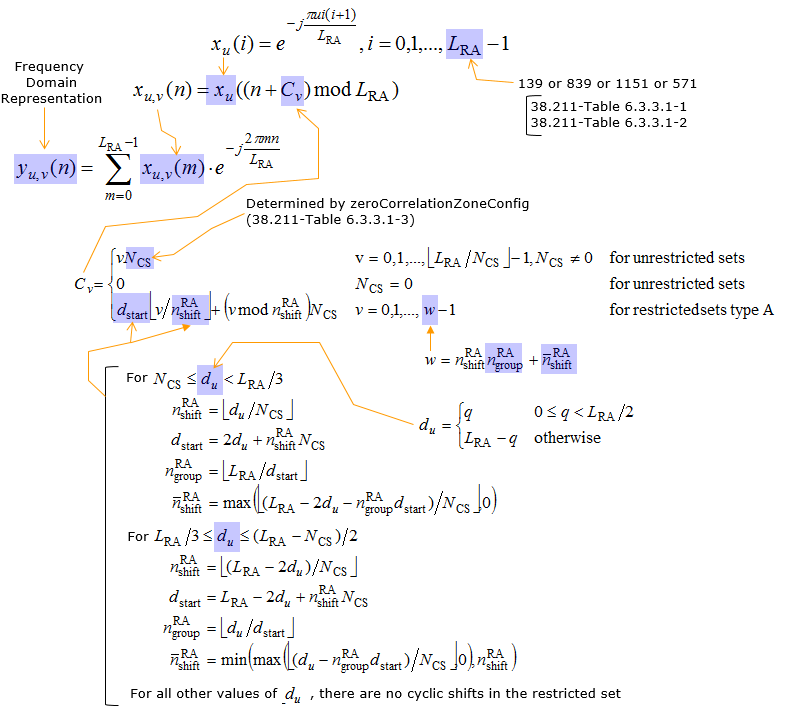
Below is the breakdown and brief description of each terms.
- The base sequence is defined as: xu(i) = e-jπui(i+1)/LRA, where i = 0, 1, ..., LRA - 1.
- u: Root index of the Zadoff-Chu sequence.
- LRA: Length of the Zadoff-Chu sequence, which can be 139, 839, 1151, or 571 depending on the preamble format.
- Cyclically shifted versions of the base sequence are generated as: xu,v(n) = xu((n + Cv) mod LRA).
- Cv: The cyclic shift value, which is calculated using parameters like NCS and du.
- The frequency domain sequence is generated as: yu,v(n) = ∑m=0LRA-1 xu,v(m) e-j2πmn/LRA.
- This summation converts the cyclically shifted Zadoff-Chu sequence into the frequency domain representation.
The summation process in the frequency domain representation formula for 5G NR PRACH serves several important purposes. The summation process in the frequency domain representation formula was introduced to handle the transition from the cyclically shifted Zadoff-Chu sequence to its frequency domain form while accommodating varying sequence lengths, subcarrier spacings, and advanced configurations. It ensures the PRACH signal generation is robust, flexible, and suitable for the diverse requirements of 5G NR. Below is a detailed explanation:
-
Explicit Representation of IDFT:
- The summation process: yu,v(n) = ∑m=0LRA-1 xu,v(m) e-j2πmn/LRA directly represents the Inverse Discrete Fourier Transform (IDFT).
- This is necessary to map the Zadoff-Chu sequence from the frequency domain to its frequency representation.
-
Flexibility with Variable Sequence Lengths (LRA):
- Unlike LTE, where the sequence length is fixed at 839, 5G NR allows variable sequence lengths (e.g., 139, 571, 839, or 1151).
- The summation process handles these varying lengths dynamically.
-
Support for Multiple Subcarrier Spacings (ΔfRA):
- 5G NR PRACH supports diverse subcarrier spacings, which influence how the sequence components align within the frequency grid.
- The summation ensures accurate modeling of each subcarrier's contribution.
-
Orthogonality Across Sequences:
- The summation ensures the orthogonality properties of the Zadoff-Chu sequence are preserved across subcarriers.
- This is critical for maintaining constant amplitude and zero-autocorrelation properties, avoiding interference in PRACH.
-
Alignment with 5G NR Resource Grid:
- The PRACH signal must align precisely with the resource grid for proper synchronization and decoding.
- The summation accounts for the distribution of sequence components across the frequency domain, ensuring accurate placement.
-
Support for Advanced Configurations (e.g., Restricted Sets):
- 5G NR introduces restricted sets and complex cyclic shift calculations to avoid collisions and address high mobility scenarios.
- The summation integrates these adjustments, such as cyclic and Doppler shifts, into the frequency domain representation.
For Unrestricted Sets (NCS ≠ 0):
- Cyclic shift is calculated as: Cv = v ⋅ NCS, where v = 0, 1, ..., ⌊LRA/NCS⌋ - 1>.
- NCS: The cyclic shift granularity determined by the zeroCorrelationZoneConfig.
For Restricted Sets (Type A):
- Cyclic shift depends on additional parameters:
- du: A Doppler shift-related parameter calculated as: du = q if 0 ≤ q < LRA/2, otherwise du = LRA - q.
- q: The smallest integer such that (q ⋅ u) mod LRA = 1.
- Case-based calculations:
- For NCS ≤ du < LRA/3: Compute nRAshift, dstart, and nRAgroup based on the equations.
- For LRA/3 ≤ du ≤ (LRA - NCS)/2: Use a different set of equations for these parameters.
- For other values of du: No cyclic shifts are applied in the restricted set.
- Zadoff-Chu Sequence Generation: Provides a fundamental sequence with zero autocorrelation and constant amplitude properties.
- Cyclic Shift Application: Ensures orthogonality between preambles, enabling multiple UEs to transmit simultaneously without interference.
- Frequency Domain Representation: Converts the sequence for transmission in the frequency domain.
- Cyclic Shift Calculation (Cv): Generates unique preambles while avoiding collisions in PRACH resources.
Bellow is the high level summary of the process
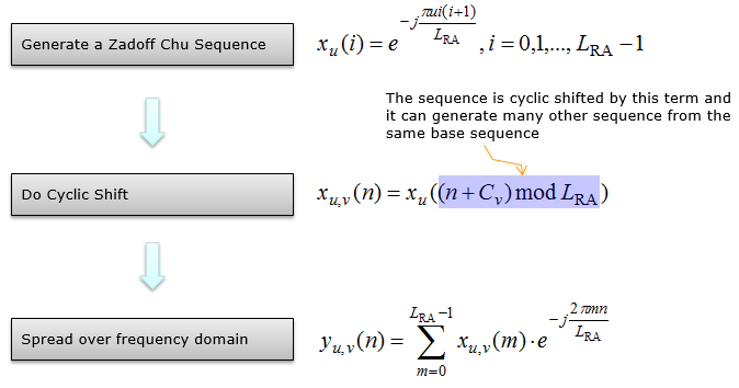
Below is the breakdown of this summary and description
-
Generate a Zadoff-Chu Sequence (xu(i)):
- The base sequence is described using the formula: xu(i) = e-jπui(i+1)/LRA, where i = 0, 1, ..., LRA - 1.
- This step highlights the fundamental process of generating the root Zadoff-Chu sequence, which serves as the building block.
-
Do Cyclic Shift (xu,v(n)):
- The cyclic shift is described with the formula: xu,v(n) = xu((n + Cv) mod LRA).
- This explains how multiple preambles are derived from the base sequence by applying cyclic shifts, ensuring orthogonality among sequences.
-
Spread Over Frequency Domain (yu,v(n)):
- The frequency domain representation is summarized as: yu,v(n) = ∑m=0LRA-1 xu,v(m) e-j2πmn/LRA.
- This describes how the cyclically shifted sequence is transformed into the frequency domain for transmission.
Time Domain Sequence Generation
Following is the equation to generate the time domain sequence for PRACH. Basically the big picture is to do IFFT to the frequency domain data generated above. As you notice here, this is very complicated and confusing equation. You would not need to understand every part. I just put down this equation with a lot of messy arrow just to highlight some of the important parameters. There are many small parameters that are not described here. For those details, refer to 38.211-5.3.2
The Time Domain Sequence Generation process for PRACH converts the frequency domain representation into the time domain using the IFFT operation and applies necessary time-domain adjustments. Below is an explanation of the process based on the diagram: This process generates the PRACH signal in the time domain, ensuring robust transmission and alignment with the resource grid. It demonstrates greater flexibility compared to LTE, supporting diverse deployment scenarios in 5G NR.
This is a few key points
- The process involves many intermediate parameters and adjustments to align the PRACH signal precisely with the 5G NR resource grid.
- PRACH duration, cyclic prefix, and frequency offset are dynamically adjusted based on the configuration index and preamble format.
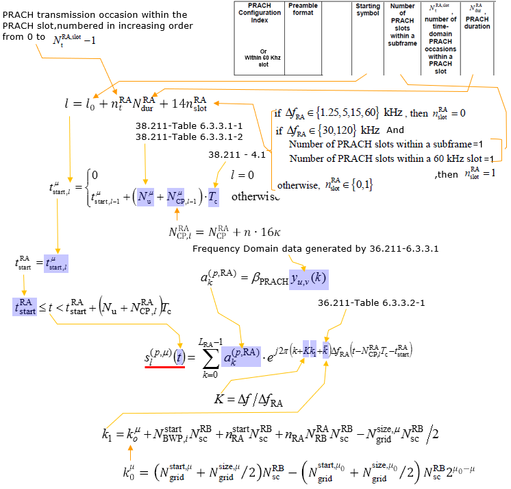
- The PRACH transmission occasion, l, determines when the PRACH preamble is transmitted within a subframe or slot.
- It is calculated using parameters such as:
- l0: The starting symbol of the PRACH occasion.
- NRAdur: Duration of the PRACH in symbols.
- NRAslot: Number of PRACH slots in a subframe.
- The value of NRAslot depends on the subcarrier spacing (ΔfRA):
- For ΔfRA = 1.25, 5, 15, 60 kHz: NRAslot = 0.
- For ΔfRA = 30, 120 kHz: NRAslot = 1.
- Determines the exact start time of the PRACH preamble in the time domain.
- If l = 0, the starting time is:
- tμ,RAstart,l = 0.
- For l ≠ 0, the calculation incorporates:
- Tc: Time unit for 5G NR (sampling period).
- NRACP,l: Cyclic prefix duration for PRACH.
- NRAu: Useful duration of PRACH.
- A cyclic prefix is added to handle multi-path propagation and maintain orthogonality.
- The value of the cyclic prefix depends on the subcarrier spacing and configuration index.
- The frequency domain representation of the PRACH sequence, generated in the frequency domain process.
- This data serves as the input for the time domain sequence generation.
- The PRACH time-domain signal is generated using the formula: s(p,μ)(t) = ∑k=0LRA-1 ak(p,RA) ej2π(k+K)(t-k1Tc).
- ak(p,RA): Frequency domain amplitude scaling factor.
- K: Frequency offset term.
- k1: Starting subcarrier index.
- k0μ: Starting subcarrier index for PRACH.
- NscRB: Number of subcarriers per resource block (12 for LTE/NR).
- ΔfRA: Subcarrier spacing, which varies depending on the configuration.
Examples
In practical perspective, you would not need to go through all the detailed process of RACH sequence generation, but it would be usefull to know how to figure out the end result of PRACH signal generation in time domain. This is expecially important when you configuring TDD UL-DL configuration because you have to make it sure that PRACH occasion should fall into UL slot/symbols of the configured TDD pattern.
Example 01 > TDD FR2 RachConfig = 70, Format A3
The row highlighted below is PRACH configuration index 70, preamble format A3. It is on this page because one occasion per PRACH slot, and the 5.3.2 condition holds so nslotRA is fixed at 1. The arrows carry the row into the l formula. The value at the bottom left is the answer.
< 38.211 v15.5-Table 6.3.3.2-4: Random access configurations for FR2 and unpaired spectrum. >
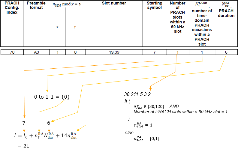
The row : index 70, format A3, x = 1 and y = 0, slot number 19, 39.Starting symbol : l0 = 7, which is where the first occasion in a slot begins.Occasion counts : NtRA,slot = 1 occasion(s) per PRACH slot, 1 PRACH slot(s) per 60 kHz slot, and NdurRA = 6 symbols.The result : l = l0 + ntRANdurRA + 14nslotRA gives l = 21.
With the calculated RACH transmission symbol and Preamble format 3 structure, RACH occasion in time domain can be illustrated as follows.
The drawing below places that result on the symbol grid, for the two 60 kHz slots the table lists, 19 and 39. The upper row is the reference grid the table counts in. The row below it is the grid the preamble is sent on, and the red blocks are the occasions at l = 21.

Slot mapping : 60 kHz slot 19 becomes 120 kHz slots 38 and 39, and the single A3 block sits at symbol 21, six symbols wide.A label to distrust : The lower panel repeats it for 60 kHz slot 39. Its left hand 120 kHz slot is labelled Slot 38, copied from the panel above. 39 × 2 is 78, so it should read Slot 78, and the right hand label of Slot 79 is correct.
Example 02 > TDD FR2 RachConfig = 71, Format A3
The row highlighted below is PRACH configuration index 71, preamble format A3. It is on this page because Nt is 2, so the same slot carries two occasions back to back. The arrows carry the row into the l formula. The value at the bottom left is the answer.
< 38.211 v15.5-Table 6.3.3.2-4: Random access configurations for FR2 and unpaired spectrum. >
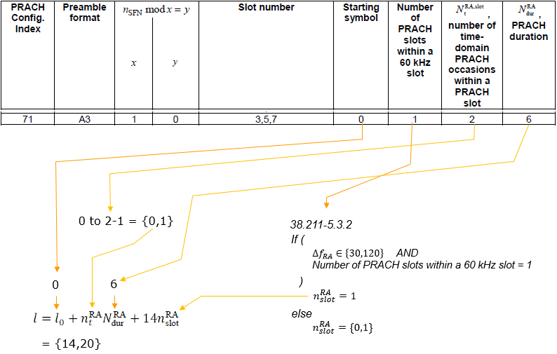
The row : index 71, format A3, x = 1 and y = 0, slot number 3, 5, 7.Starting symbol : l0 = 0, which is where the first occasion in a slot begins.Occasion counts : NtRA,slot = 2 occasion(s) per PRACH slot, 1 PRACH slot(s) per 60 kHz slot, and NdurRA = 6 symbols.The result : l = l0 + ntRANdurRA + 14nslotRA gives l = {14, 20}.
With the calculated RACH transmission symbol and Preamble format 3 structure, RACH occasion in time domain can be illustrated as follows.
The drawing below places that result on the symbol grid, for the first two of the three slots, 3 and 5. The upper row is the reference grid the table counts in. The row below it is the grid the preamble is sent on, and the red blocks are the occasions at l = {14, 20}.
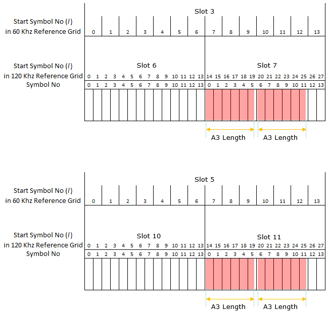
Slot mapping : 60 kHz slot 3 becomes 120 kHz slots 6 and 7, and slot 5 becomes 10 and 11.Where the blocks land : Both A3 blocks land in the second 120 kHz slot, at continuous symbols 14 to 19 and 20 to 25. That is the {14, 20} the table derived.
The drawing below places that result on the symbol grid, for the last of the three slots, 7. The upper row is the reference grid the table counts in. The row below it is the grid the preamble is sent on, and the red blocks are the occasions at l = {14, 20}.

Slot mapping : 60 kHz slot 7 becomes 120 kHz slots 14 and 15.Where the blocks land : The two A3 blocks sit at the same continuous symbols 14 and 20 as the panels above, so the pattern repeats unchanged from slot to slot.
Example 03 > TDD FR2 RachConfig = 74, Format A3
The row highlighted below is PRACH configuration index 74, preamble format A3. It is on this page because two PRACH slots per 60 kHz slot, so the 5.3.2 condition fails and nslotRA takes both values. The arrows carry the row into the l formula. The value at the bottom left is the answer.
< 38.211 v15.5-Table 6.3.3.2-4: Random access configurations for FR2 and unpaired spectrum. >
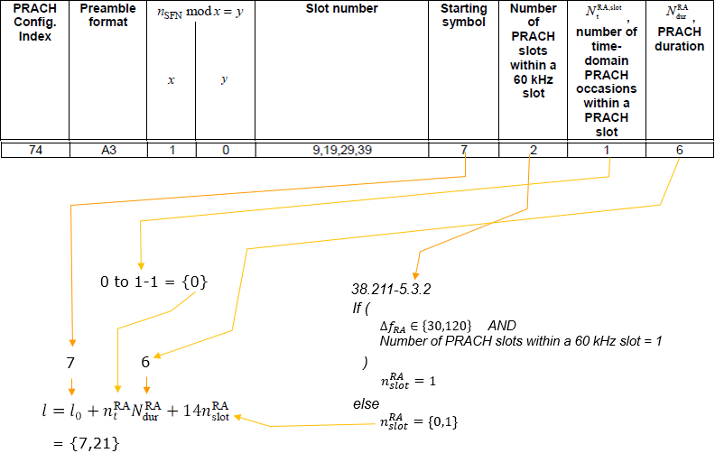
The row : index 74, format A3, x = 1 and y = 0, slot number 9, 19, 29, 39.Starting symbol : l0 = 7, which is where the first occasion in a slot begins.Occasion counts : NtRA,slot = 1 occasion(s) per PRACH slot, 2 PRACH slot(s) per 60 kHz slot, and NdurRA = 6 symbols.The result : l = l0 + ntRANdurRA + 14nslotRA gives l = {7, 21}.
With the calculated RACH transmission symbol and Preamble format 3 structure, RACH occasion in time domain can be illustrated as follows.
The drawing below places that result on the symbol grid, for the first two slots, 9 and 19. The upper row is the reference grid the table counts in. The row below it is the grid the preamble is sent on, and the red blocks are the occasions at l = {7, 21}.

Slot mapping : Each panel is labelled with nslotRA = 0 on the left and 1 on the right. That is the visible form of the {7, 21} result.Where the blocks land : One A3 block sits in each 120 kHz slot rather than two in one. That is what having two PRACH slots per 60 kHz slot means.
The drawing below places that result on the symbol grid, for the last two slots, 29 and 39. The upper row is the reference grid the table counts in. The row below it is the grid the preamble is sent on, and the red blocks are the occasions at l = {7, 21}.
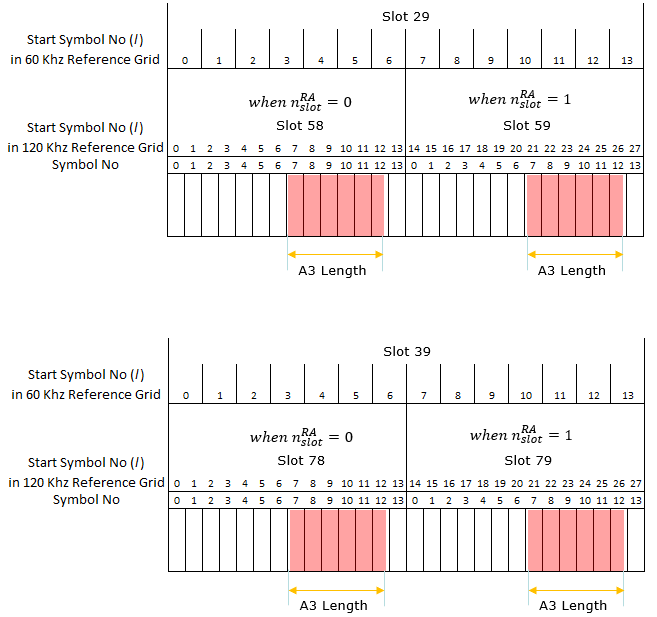
Slot mapping : 60 kHz slot 29 becomes 120 kHz slots 58 and 59, and slot 39 becomes 78 and 79.A cross check : These panels label the second slot pair correctly as 78 and 79. That is the check that the Slot 38 label in Example 01 is a slip.
Example 04 > TDD FR2 RachConfig = 76, Format A3
The row highlighted below is PRACH configuration index 76, preamble format A3. It is on this page because both multipliers are 2. That is what produces four occasions rather than one. The arrows carry the row into the l formula. The value at the bottom left is the answer.
< 38.211 v15.5- Table 6.3.3.2-4: Random access configurations for FR2 and unpaired spectrum. >
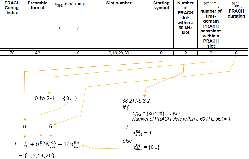
The row : index 76, format A3, x = 1 and y = 0, slot number 9, 19, 29, 39.Starting symbol : l0 = 0, which is where the first occasion in a slot begins.Occasion counts : NtRA,slot = 2 occasion(s) per PRACH slot, 2 PRACH slot(s) per 60 kHz slot, and NdurRA = 6 symbols.The result : l = l0 + ntRANdurRA + 14nslotRA gives l = {0, 6, 14, 20}.
With the calculated RACH transmission symbol and Preamble format 3 structure, RACH occasion in time domain can be illustrated as follows.
The drawing below places that result on the symbol grid, for the first two slots, 9 and 19. The upper row is the reference grid the table counts in. The row below it is the grid the preamble is sent on, and the red blocks are the occasions at l = {0, 6, 14, 20}.

Slot mapping : Every block is annotated with both indices, nslotRA above and ntRA below.Where the blocks land : Four A3 blocks appear per 60 kHz slot, at continuous symbols 0, 6, 14 and 20, matching the four values the table derived.
The drawing below places that result on the symbol grid, for the last two slots, 29 and 39. The upper row is the reference grid the table counts in. The row below it is the grid the preamble is sent on, and the red blocks are the occasions at l = {0, 6, 14, 20}.

Slot mapping : The layout is identical to the panels above, applied to 120 kHz slots 58 and 59, then 78 and 79.Where the blocks land : Symbols 12, 13, 26 and 27 stay white in every panel. Four blocks of six symbols leave two spare at the end of each 120 kHz slot.
Example 05 > TDD FR2 RachConfig = 12, Format A1
The row highlighted below is PRACH configuration index 12, preamble format A1. It is on this page because A1 is two symbols rather than six, and the room that frees is what lets Nt reach 3. The arrows carry the row into the l formula. The value at the bottom left is the answer.
< 38.211 v15.5- Table 6.3.3.2-4: Random access configurations for FR2 and unpaired spectrum. >
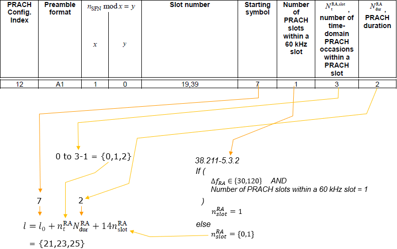
The row : index 12, format A1, x = 1 and y = 0, slot number 19, 39.Starting symbol : l0 = 7, which is where the first occasion in a slot begins.Occasion counts : NtRA,slot = 3 occasion(s) per PRACH slot, 1 PRACH slot(s) per 60 kHz slot, and NdurRA = 2 symbols.The result : l = l0 + ntRANdurRA + 14nslotRA gives l = {21, 23, 25}.
With the calculated RACH transmission symbol and Preamble format 3 structure, RACH occasion in time domain can be illustrated as follows.
The drawing below places that result on the symbol grid, for both slots the table lists, 19 and 39. The upper row is the reference grid the table counts in. The row below it is the grid the preamble is sent on, and the red blocks are the occasions at l = {21, 23, 25}.
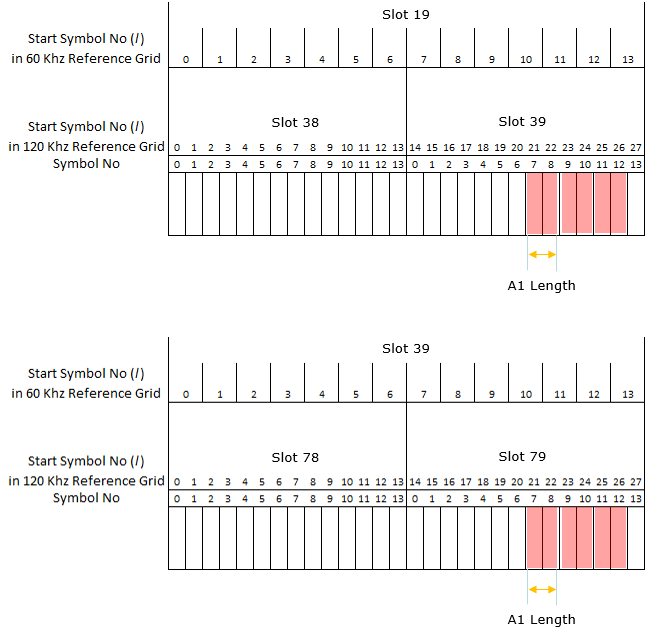
Slot mapping : Three separate A1 blocks appear rather than one long one, at continuous symbols 21, 23 and 25.Where the blocks land : Each block is two symbols wide, so the three of them occupy the same span one A3 block would.
Example 06 > TDD FR2 RachConfig = 8, Format A1
The row highlighted below is PRACH configuration index 8, preamble format A1. It is on this page because x is 2 and y is 1, so this configuration only appears in odd numbered frames. Twelve occasions is also the densest case shown here. The arrows carry the row into the l formula. The value at the bottom left is the answer.
< 38.211 v15.5-Table 6.3.3.2-4: Random access configurations for FR2 and unpaired spectrum. >
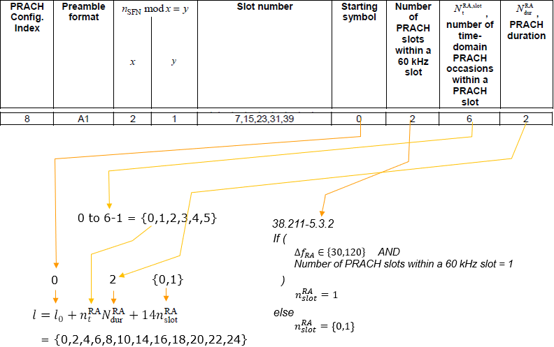
The row : index 8, format A1, x = 2 and y = 1, slot number 7, 15, 23, 31, 39.Starting symbol : l0 = 0, which is where the first occasion in a slot begins.Occasion counts : NtRA,slot = 6 occasion(s) per PRACH slot, 2 PRACH slot(s) per 60 kHz slot, and NdurRA = 2 symbols.The result : l = l0 + ntRANdurRA + 14nslotRA gives l = {0, 2, 4, 6, 8, 10, 14, 16, 18, 20, 22, 24}.It does not occur every frame : x = 2 and y = 1, so the condition nSFN mod 2 = 1 only holds in some frames.
With the calculated RACH transmission symbol and Preamble format 3 structure, RACH occasion in time domain can be illustrated as follows.
The drawing below places that result on the symbol grid, for the first two slots, 7 and 15, in the odd numbered frame. The upper row is the reference grid the table counts in. The row below it is the grid the preamble is sent on, and the red blocks are the occasions at l = {0, 2, 4, 6, 8, 10, 14, 16, 18, 20, 22, 24}.
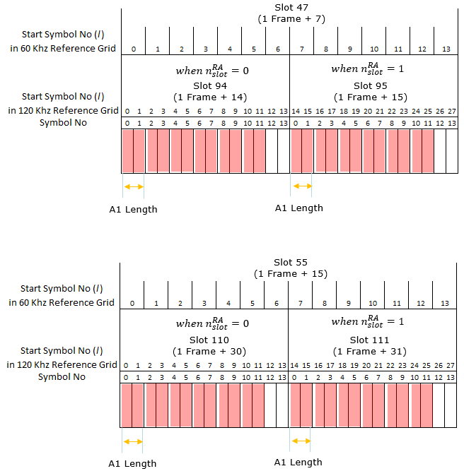
Slot mapping : The slot labels carry both numbers. Slot 47 is written as 1 Frame + 7, and its 120 kHz pair is 94 and 95.Where the blocks land : Six A1 blocks fill each 120 kHz slot at even symbols 0 to 10. The second slot repeats them at 14 to 24.
The drawing below places that result on the symbol grid, for the next two slots, 23 and 31. The upper row is the reference grid the table counts in. The row below it is the grid the preamble is sent on, and the red blocks are the occasions at l = {0, 2, 4, 6, 8, 10, 14, 16, 18, 20, 22, 24}.
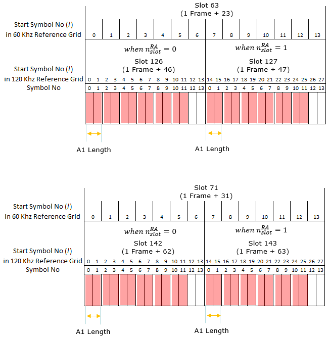
Slot mapping : Slot 63 is 1 Frame + 23 and maps to 120 kHz slots 126 and 127. Slot 71 is 1 Frame + 31 and maps to 142 and 143.Where the blocks land : The twelve blocks per 60 kHz slot are unchanged. That is the point of showing four separate panels.
The drawing below places that result on the symbol grid, for the last slot, 39. The upper row is the reference grid the table counts in. The row below it is the grid the preamble is sent on, and the red blocks are the occasions at l = {0, 2, 4, 6, 8, 10, 14, 16, 18, 20, 22, 24}.

Slot mapping : Slot 79 is 1 Frame + 39 and maps to 120 kHz slots 158 and 159.Where the blocks land : This is the last of the five slots the table lists, and the occasion pattern is identical to the four before it.
Example 07 > TDD FR1 RachConfig = 4, SCS = 15Khz, Format 0
The row highlighted below is PRACH configuration index 4, preamble format 0. It is on this page because a long preamble format, where Ndur is 0 and the formula collapses to the starting symbol alone. The arrows carry the row into the l formula. The value at the bottom left is the answer.
< 38.211 v15.3.0-Table 6.3.3.2-3: Random access configurations for FR1 and unpaired spectrum >
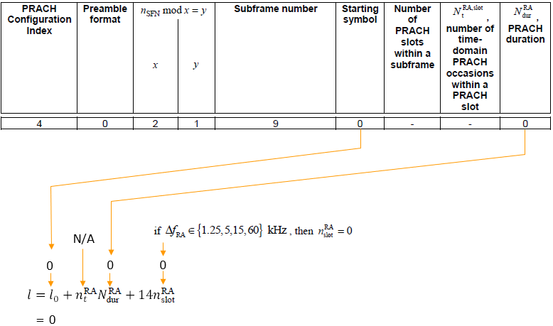
The row : index 4, format 0, x = 2 and y = 1, subframe number 9.Starting symbol : l0 = 0, which is where the first occasion in a slot begins.The occasion counts are absent : NtRA,slot and the PRACH slot count are both a dash, and NdurRA is 0. A long format occupies the whole subframe.The result : l = l0 + ntRANdurRA + 14nslotRA gives l = 0.It does not occur every frame : x = 2 and y = 1, so the condition nSFN mod 2 = 1 only holds in some frames.
Example 08 > TDD FR1 RachConfig = 79, SCS = 30Khz, Format A1
The row highlighted below is PRACH configuration index 79, preamble format A1. It is on this page because the FR1 table, so the reference grid is 15 kHz against 30 kHz rather than 60 against 120. The arrows carry the row into the l formula. The value at the bottom left is the answer.
< 38.211 v15.3.0-Table 6.3.3.2-3: Random access configurations for FR1 and unpaired spectrum >

The row : index 79, format A1, x = 1 and y = 0, subframe number 9.Starting symbol : l0 = 0, which is where the first occasion in a slot begins.Occasion counts : NtRA,slot = 6 occasion(s) per PRACH slot, 1 PRACH slot(s) per subframe, and NdurRA = 2 symbols.The result : l = l0 + ntRANdurRA + 14nslotRA gives l = {14, 16, 18, 20, 22, 24}.
The drawing below places that result on the symbol grid, for the single subframe the table lists, 9. The upper row is the reference grid the table counts in. The row below it is the grid the preamble is sent on, and the red blocks are the occasions at l = {14, 16, 18, 20, 22, 24}.
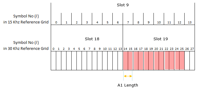
Slot mapping : The reference grids are 15 kHz and 30 kHz here rather than 60 and 120, because this is an FR1 configuration.Where the blocks land : 15 kHz slot 9 becomes 30 kHz slots 18 and 19, and the six A1 blocks sit at even symbols 14 to 24.
Example 09 > TDD FR1 RachConfig = 78, SCS = 30 Khz, Format A1
The row highlighted below is PRACH configuration index 78, preamble format A1. It is on this page because the same shape as the configuration above with a starting symbol of 7 instead of 0. The arrows carry the row into the l formula. The value at the bottom left is the answer.
< 38.211 v15.3.0-Table 6.3.3.2-3: Random access configurations for FR1 and unpaired spectrum >
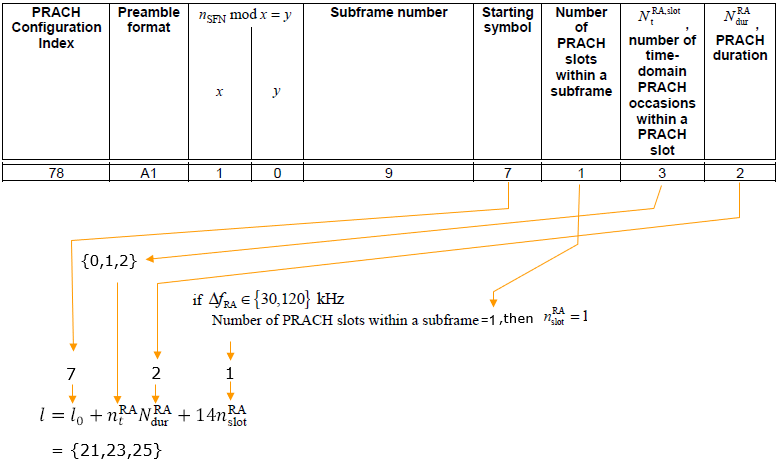
The row : index 78, format A1, x = 1 and y = 0, subframe number 9.Starting symbol : l0 = 7, which is where the first occasion in a slot begins.Occasion counts : NtRA,slot = 3 occasion(s) per PRACH slot, 1 PRACH slot(s) per subframe, and NdurRA = 2 symbols.The result : l = l0 + ntRANdurRA + 14nslotRA gives l = {21, 23, 25}.
The drawing below places that result on the symbol grid, for the single subframe the table lists, 9. The upper row is the reference grid the table counts in. The row below it is the grid the preamble is sent on, and the red blocks are the occasions at l = {21, 23, 25}.
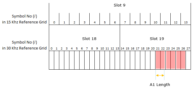
Slot mapping : 15 kHz slot 9 becomes 30 kHz slots 18 and 19, the same mapping as the configuration above.Where the blocks land : Three A1 blocks sit at symbols 21, 23 and 25. That is the starting symbol of 7 carried into the second 30 kHz slot.
Example 10 > TDD FR1 RachConfig = 131, SCS = 30 Khz, Format A3
The row highlighted below is PRACH configuration index 131, preamble format A3. It is on this page because five subframes carry the same pair of occasions, which is the densest spacing in the FR1 A3 rows. The arrows carry the row into the l formula. The value at the bottom left is the answer.
< 38.211 v15.3.0-Table 6.3.3.2-3: Random access configurations for FR1 and unpaired spectrum >
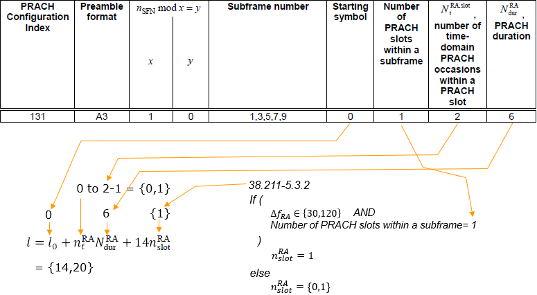
The row : index 131, format A3, x = 1 and y = 0, subframe number 1, 3, 5, 7, 9.Starting symbol : l0 = 0, which is where the first occasion in a slot begins.Occasion counts : NtRA,slot = 2 occasion(s) per PRACH slot, 1 PRACH slot(s) per subframe, and NdurRA = 6 symbols.The result : l = l0 + ntRANdurRA + 14nslotRA gives l = {14, 20}.
The drawing below places that result on the symbol grid, for subframe 1. The upper row is the reference grid the table counts in. The row below it is the grid the preamble is sent on, and the red blocks are the occasions at l = {14, 20}.

Slot mapping : 15 kHz slot 1 becomes 30 kHz slots 2 and 3.Where the blocks land : Both A3 blocks land in the right hand slot, at continuous symbols 14 to 19 and 20 to 25.
The drawing below places that result on the symbol grid, for subframe 3. The upper row is the reference grid the table counts in. The row below it is the grid the preamble is sent on, and the red blocks are the occasions at l = {14, 20}.
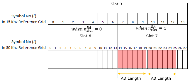
Slot mapping : 15 kHz slot 3 becomes 30 kHz slots 6 and 7.Where the blocks land : The block positions are identical to the panel above. That is what makes the configuration predictable across subframes.
The drawing below places that result on the symbol grid, for subframe 5. The upper row is the reference grid the table counts in. The row below it is the grid the preamble is sent on, and the red blocks are the occasions at l = {14, 20}.
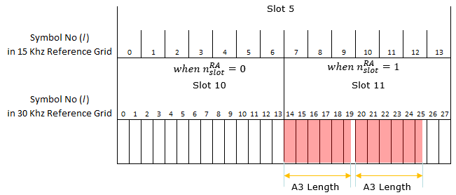
Slot mapping : 15 kHz slot 5 becomes 30 kHz slots 10 and 11.Where the blocks land : Two A3 blocks again, at the same continuous symbols 14 and 20.
The drawing below places that result on the symbol grid, for subframe 7. The upper row is the reference grid the table counts in. The row below it is the grid the preamble is sent on, and the red blocks are the occasions at l = {14, 20}.
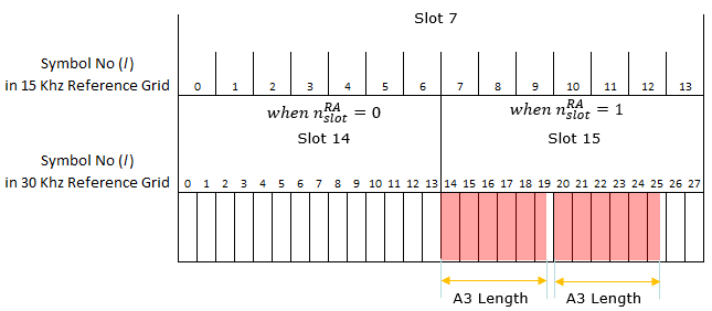
Slot mapping : 15 kHz slot 7 becomes 30 kHz slots 14 and 15.Where the blocks land : The pattern is unchanged from the three panels above.
The drawing below places that result on the symbol grid, for subframe 9. The upper row is the reference grid the table counts in. The row below it is the grid the preamble is sent on, and the red blocks are the occasions at l = {14, 20}.
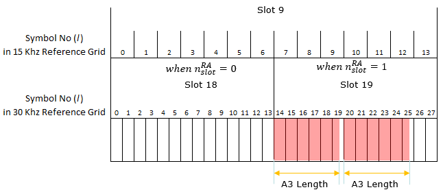
Slot mapping : 15 kHz slot 9 becomes 30 kHz slots 18 and 19.Where the blocks land : This is the fifth and last of the subframes the table lists, closing the set at symbols 14 and 20.
Example 11 > TDD FR1 RachConfig = 128, SCS = 30 Khz, Format A3
The row highlighted below is PRACH configuration index 128, preamble format A3. It is on this page because a single occasion per slot, which is the sparsest configuration shown here. The arrows carry the row into the l formula. The value at the bottom left is the answer.
< 38.211 v15.3.0-Table 6.3.3.2-3: Random access configurations for FR1 and unpaired spectrum >
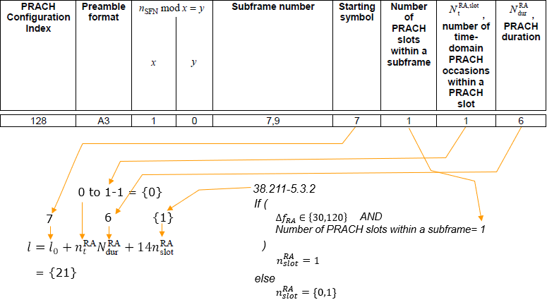
The row : index 128, format A3, x = 1 and y = 0, subframe number 7, 9.Starting symbol : l0 = 7, which is where the first occasion in a slot begins.Occasion counts : NtRA,slot = 1 occasion(s) per PRACH slot, 1 PRACH slot(s) per subframe, and NdurRA = 6 symbols.The result : l = l0 + ntRANdurRA + 14nslotRA gives l = {21}.
The drawing below places that result on the symbol grid, for the first subframe, 7. The upper row is the reference grid the table counts in. The row below it is the grid the preamble is sent on, and the red blocks are the occasions at l = {21}.
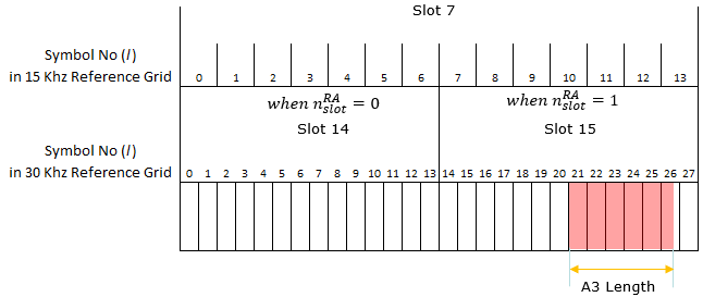
Slot mapping : 15 kHz slot 7 becomes 30 kHz slots 14 and 15.Where the blocks land : A single A3 block sits at continuous symbols 21 to 26, and nothing occupies the left hand 30 kHz slot.
The drawing below places that result on the symbol grid, for the second subframe, 9. The upper row is the reference grid the table counts in. The row below it is the grid the preamble is sent on, and the red blocks are the occasions at l = {21}.
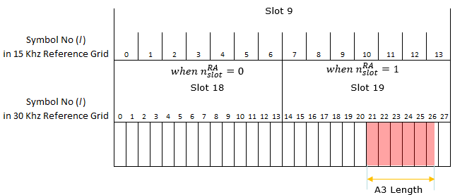
Slot mapping : 15 kHz slot 9 becomes 30 kHz slots 18 and 19.Where the blocks land : The same single block appears at symbol 21, which is the sparsest occasion pattern shown on this page.
Example 12 > TDD FR1 RachConfig = 133, SCS = 30 Khz, Format B1
The row highlighted below is PRACH configuration index 133, preamble format B1. It is on this page because the first B format on this page, and x is 4, so it recurs only once every four frames. The arrows carry the row into the l formula. The value at the bottom left is the answer.
< 38.211 v15.3.0-Table 6.3.3.2-3: Random access configurations for FR1 and unpaired spectrum >
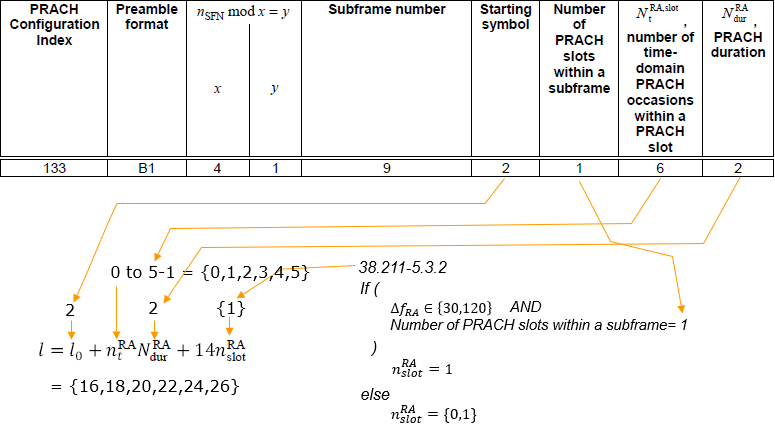
The row : index 133, format B1, x = 4 and y = 1, subframe number 9.Starting symbol : l0 = 2, which is where the first occasion in a slot begins.Occasion counts : NtRA,slot = 6 occasion(s) per PRACH slot, 1 PRACH slot(s) per subframe, and NdurRA = 2 symbols.The result : l = l0 + ntRANdurRA + 14nslotRA gives l = {16, 18, 20, 22, 24, 26}.It does not occur every frame : x = 4 and y = 1, so the condition nSFN mod 4 = 1 only holds in some frames.
The drawing below places that result on the symbol grid, for the single subframe the table lists, 9. The upper row is the reference grid the table counts in. The row below it is the grid the preamble is sent on, and the red blocks are the occasions at l = {16, 18, 20, 22, 24, 26}.

Slot mapping : 15 kHz subframe 9 becomes 30 kHz slots 18 and 19.Where the blocks land : Six B1 blocks sit at even symbols 16 to 26, two symbols each. They start two symbols later than the A1 case above, because l0 is 2.
Example 13 > TDD FR1 RachConfig = 136, SCS = 30 Khz, Format B1
The row highlighted below is PRACH configuration index 136, preamble format B1. It is on this page because a starting symbol of 8, which pushes all three occasions into the second half of the slot. The arrows carry the row into the l formula. The value at the bottom left is the answer.
< 38.211 v15.3.0-Table 6.3.3.2-3: Random access configurations for FR1 and unpaired spectrum >
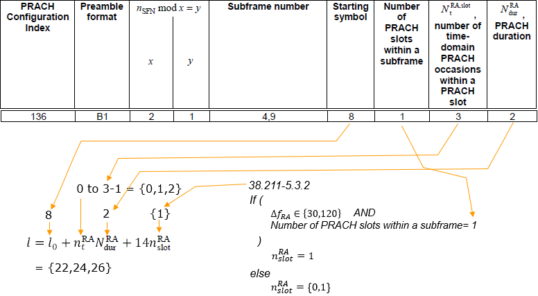
The row : index 136, format B1, x = 2 and y = 1, subframe number 4, 9.Starting symbol : l0 = 8, which is where the first occasion in a slot begins.Occasion counts : NtRA,slot = 3 occasion(s) per PRACH slot, 1 PRACH slot(s) per subframe, and NdurRA = 2 symbols.The result : l = l0 + ntRANdurRA + 14nslotRA gives l = {22, 24, 26}.It does not occur every frame : x = 2 and y = 1, so the condition nSFN mod 2 = 1 only holds in some frames.
The drawing below places that result on the symbol grid, for the first subframe, 4. The upper row is the reference grid the table counts in. The row below it is the grid the preamble is sent on, and the red blocks are the occasions at l = {22, 24, 26}.
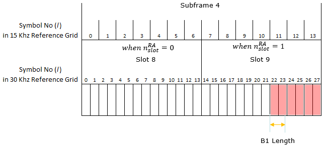
Slot mapping : 15 kHz subframe 4 becomes 30 kHz slots 8 and 9.Where the blocks land : Three B1 blocks sit at symbols 22, 24 and 26, right at the end of the second slot. The starting symbol is 8.
The drawing below places that result on the symbol grid, for the second subframe, 9. The upper row is the reference grid the table counts in. The row below it is the grid the preamble is sent on, and the red blocks are the occasions at l = {22, 24, 26}.
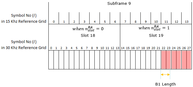
Slot mapping : 15 kHz subframe 9 becomes 30 kHz slots 18 and 19.Where the blocks land : The three blocks occupy the same positions as the panel above, ending at symbol 27.
Example 14 > TDD FR1 RachConfig = 141, SCS = 30 Khz, Format B1
The row highlighted below is PRACH configuration index 141, preamble format B1. It is on this page because two PRACH slots and six occasions in each, giving twelve in a subframe. The arrows carry the row into the l formula. The value at the bottom left is the answer.
< 38.211 v15.3.0-Table 6.3.3.2-3: Random access configurations for FR1 and unpaired spectrum >
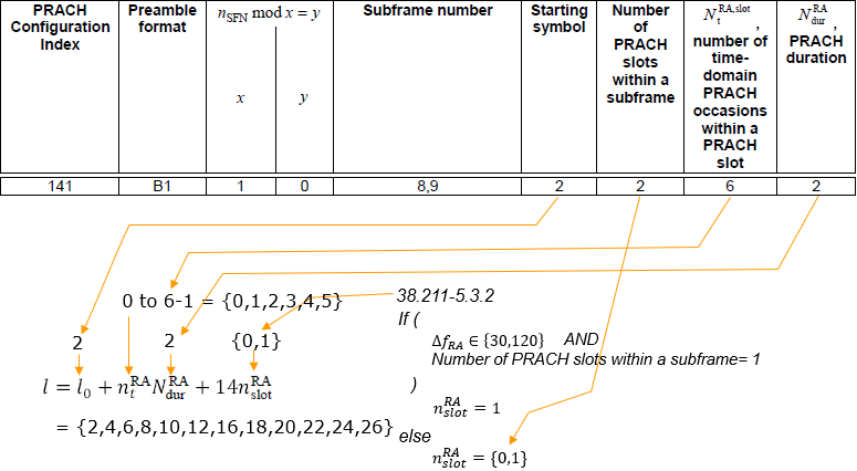
The row : index 141, format B1, x = 1 and y = 0, subframe number 8, 9.Starting symbol : l0 = 2, which is where the first occasion in a slot begins.Occasion counts : NtRA,slot = 6 occasion(s) per PRACH slot, 2 PRACH slot(s) per subframe, and NdurRA = 2 symbols.The result : l = l0 + ntRANdurRA + 14nslotRA gives l = {2, 4, 6, 8, 10, 12, 16, 18, 20, 22, 24, 26}.
The drawing below places that result on the symbol grid, for the first subframe, 8. The upper row is the reference grid the table counts in. The row below it is the grid the preamble is sent on, and the red blocks are the occasions at l = {2, 4, 6, 8, 10, 12, 16, 18, 20, 22, 24, 26}.

Slot mapping : 15 kHz subframe 8 becomes 30 kHz slots 16 and 17.Where the blocks land : Twelve B1 blocks appear, six in each 30 kHz slot. They start at symbols 2 and 16.
The drawing below places that result on the symbol grid, for the second subframe, 9. The upper row is the reference grid the table counts in. The row below it is the grid the preamble is sent on, and the red blocks are the occasions at l = {2, 4, 6, 8, 10, 12, 16, 18, 20, 22, 24, 26}.
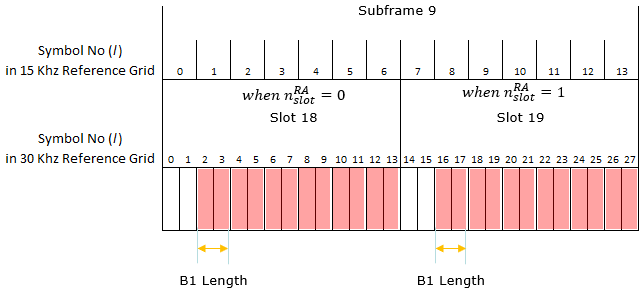
Slot mapping : 15 kHz subframe 9 becomes 30 kHz slots 18 and 19.Where the blocks land : The same twelve blocks appear. That is what two PRACH slots per subframe combined with six occasions each produces.
Example 15 > TDD FR1 RachConfig = 160, SCS = 30 Khz, Format B4
The row highlighted below is PRACH configuration index 160, preamble format B4. It is on this page because B4 is twelve symbols long, so one occasion consumes almost the whole slot and Nt can only be 1. The arrows carry the row into the l formula. The value at the bottom left is the answer.
< 38.211 v15.3.0-Table 6.3.3.2-3: Random access configurations for FR1 and unpaired spectrum >
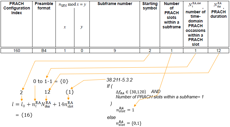
The row : index 160, format B4, x = 1 and y = 0, subframe number 9.Starting symbol : l0 = 2, which is where the first occasion in a slot begins.Occasion counts : NtRA,slot = 1 occasion(s) per PRACH slot, 1 PRACH slot(s) per subframe, and NdurRA = 12 symbols.The result : l = l0 + ntRANdurRA + 14nslotRA gives l = {16}.
The drawing below places that result on the symbol grid, for the single subframe the table lists, 9. The upper row is the reference grid the table counts in. The row below it is the grid the preamble is sent on, and the red blocks are the occasions at l = {16}.
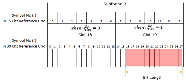
Slot mapping : 15 kHz subframe 9 becomes 30 kHz slots 18 and 19.Where the blocks land : One B4 block spans continuous symbols 16 to 27, twelve symbols wide. It fills the second 30 kHz slot almost completely.
Example 16 > TDD FR1 RachConfig = 156, SCS = 30 Khz, Format B4
The row highlighted below is PRACH configuration index 156, preamble format B4. It is on this page because the same B4 shape as above with a starting symbol of 0. The arrows carry the row into the l formula. The value at the bottom left is the answer.
< 38.211 v15.3.0-Table 6.3.3.2-3: Random access configurations for FR1 and unpaired spectrum >
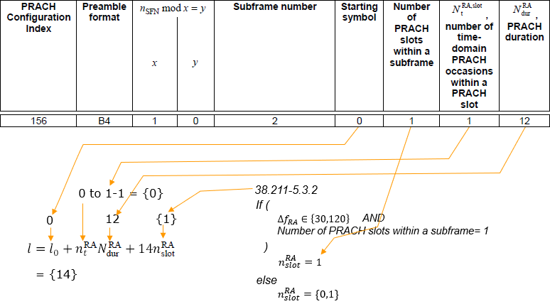
The row : index 156, format B4, x = 1 and y = 0, subframe number 2.Starting symbol : l0 = 0, which is where the first occasion in a slot begins.Occasion counts : NtRA,slot = 1 occasion(s) per PRACH slot, 1 PRACH slot(s) per subframe, and NdurRA = 12 symbols.The result : l = l0 + ntRANdurRA + 14nslotRA gives l = {14}.
The drawing below places that result on the symbol grid, for the single subframe the table lists, 2. The upper row is the reference grid the table counts in. The row below it is the grid the preamble is sent on, and the red blocks are the occasions at l = {14}.
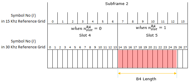
Slot mapping : 15 kHz subframe 2 becomes 30 kHz slots 4 and 5.Where the blocks land : The single B4 block spans symbols 14 to 25. That is two symbols earlier than the configuration above, because the starting symbol is 0 rather than 2.
Example 17> TDD FR2 RachConfig = 149, Format C0
The row highlighted below is PRACH configuration index 149, preamble format C0. It is on this page because C0 with Nt of 7, the largest occasion count per slot on this page. The arrows carry the row into the l formula. The value at the bottom left is the answer.
< 38.211 v15.5-Table 6.3.3.2-4: Random access configurations for FR2 and unpaired spectrum. >
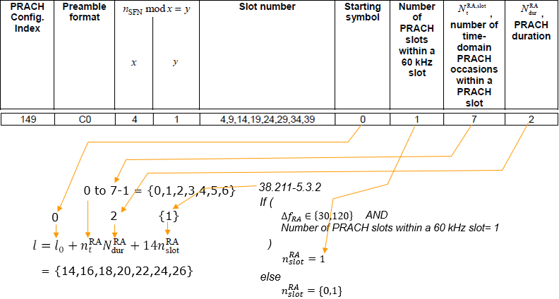
The row : index 149, format C0, x = 4 and y = 1, slot number 4, 9, 14, 19, 24, 29, 34, 39.Starting symbol : l0 = 0, which is where the first occasion in a slot begins.Occasion counts : NtRA,slot = 7 occasion(s) per PRACH slot, 1 PRACH slot(s) per 60 kHz slot, and NdurRA = 2 symbols.The result : l = l0 + ntRANdurRA + 14nslotRA gives l = {14, 16, 18, 20, 22, 24, 26}.It does not occur every frame : x = 4 and y = 1, so the condition nSFN mod 4 = 1 only holds in some frames.
The drawing below places that result on the symbol grid, for the first two slots, 4 and 9. The upper row is the reference grid the table counts in. The row below it is the grid the preamble is sent on, and the red blocks are the occasions at l = {14, 16, 18, 20, 22, 24, 26}.
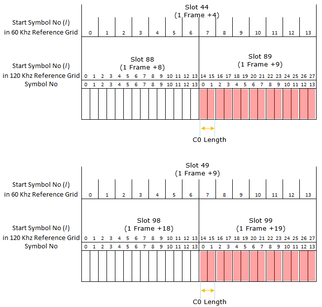
Slot mapping : Slot 44 is written as 1 Frame + 4 and maps to 120 kHz slots 88 and 89. Slot 49 maps to 98 and 99.Where the blocks land : Seven C0 blocks fill the second 120 kHz slot at even symbols 14 to 26. Only symbol 27 is left free.
The drawing below places that result on the symbol grid, for the next two slots, 14 and 19. The upper row is the reference grid the table counts in. The row below it is the grid the preamble is sent on, and the red blocks are the occasions at l = {14, 16, 18, 20, 22, 24, 26}.
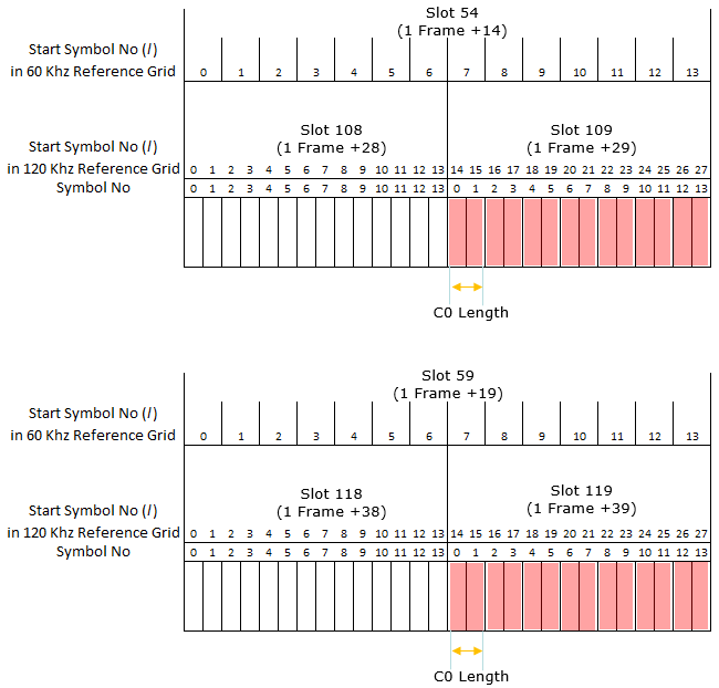
Slot mapping : Slot 54 is 1 Frame + 14 and maps to 120 kHz slots 108 and 109. Slot 59 maps to 118 and 119.Where the blocks land : The seven blocks sit at the same positions. The same holds for every slot in the list.
The drawing below places that result on the symbol grid, for the next two slots, 29 and 34. The upper row is the reference grid the table counts in. The row below it is the grid the preamble is sent on, and the red blocks are the occasions at l = {14, 16, 18, 20, 22, 24, 26}.

Slot mapping : Slot 69 is 1 Frame + 29 mapping to 120 kHz slots 138 and 139.A label to distrust : The lower panel is labelled Slot 34 (1 Frame + 34), but its 120 kHz slots are 148 and 149. Those belong to 60 kHz slot 74. Every other panel follows 40 plus the offset, so the absolute number should read 74.
The drawing below places that result on the symbol grid, for the last slot, 39. The upper row is the reference grid the table counts in. The row below it is the grid the preamble is sent on, and the red blocks are the occasions at l = {14, 16, 18, 20, 22, 24, 26}.
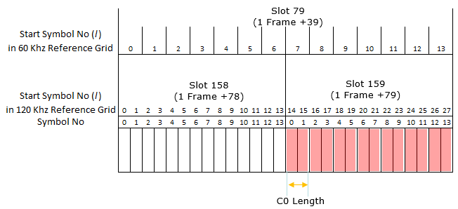
Slot mapping : Slot 79 is 1 Frame + 39 and maps to 120 kHz slots 158 and 159.Where the blocks land : This closes the set of eight slots the table lists for configuration index 149.
Impact of Rach Occasion on Scheduling and TDD UL/DL Configuration
As you saw in the examples shown above, you would notice that figuring out exact rach occasion in time domain take some effort and sometimes confusing. In addition, there are further complications caused by RACH Occasion. Even if a UE does not transmit the rach at every possible Rach Occasion, network has to schedule PDCCH, PDSCH and to configure tdd-ul-dl-config in such a way that those valid RACH Occasion is always avaiable for the UE.
Another important thing to consider when you pick a specific Rach configuration index to use, you need to be careful that the RO is not overlapping with SSB symbols or keep a certan distance (Ngap) from the SSB.
These restrictions on validity of Rach Configuration Index (determining Rach Occasion) or validity of PDCCH, PDSCH, CSI-RS locations are specified by following specification.
38.213-8.1
For paired spectrum(FDD),
all PRACH occasions are valid.
For unpaired spectrum(TDD),
Case 1 : tdd-UL-DLConfigurationCommon is NOT configured,
a PRACH occasion in a PRACH slot is valid if it does not precede a SS/PBCH block in the
PRACH slot and starts at least Ngap symbols after a last SS/PBCH block reception symbol
Case 2 : tdd-UL-DL-ConfigurationCommon is configured,
a PRACH occasion in a PRACH slot is valid if it is within UL symbols, or
a PRACH occasion in a PRACH slot is valid if it does not precede a SS/PBCH block in the PRACH slot and starts at least Ngap symbols after a last downlink symbol and at least Ngap symbols after a last SS/PBCH block transmission symbol
< 38.213 - Table 8.1-2: Ngap values for different preamble SCS >

38.213-11.1
For a set of symbols of a slot corresponding to a valid PRACH occasion and Ngap symbols before the valid PRACH occasion, as described in Sublcause 8.1, the UE does not receive PDCCH, PDSCH, or CSI-RS in the slot if a reception would overlap with any symbol from the set of symbols. The UE does not expect the set of symbols of the slot to be indicated as downlink by tdd-UL-DL-ConfigurationCommon or tdd-UL-DL-ConfigurationDedicated.
38.213-11.1.1
For a set of symbols of a slot i corresponding to a valid PRACH occasion and Ngap symbols before the valid PRACH occasion, as described in Sublcause 8.1, the UE does not expect to detect a DCI format 2_0 with an SFI-index field value indicating the set of symbols of the slot as downlink.
zeroCorrelationZoneConfig and Ncs
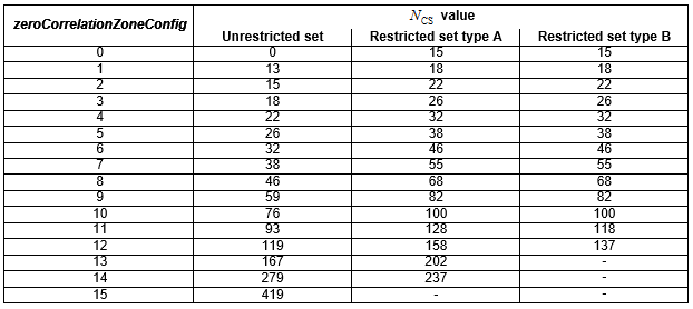
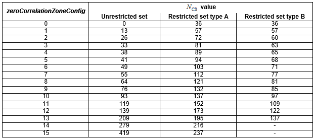
Ncs is not configured directly. The network sends zeroCorrelationZoneConfig, an integer from 0 to 15. The UE then looks Ncs up in a table chosen by the preamble format and the restricted set type. The tables below are that lookup.
The Ncs in the above equation is determined by zeroCorrelationZoneConfig in RRC message and the value is determined by the following mapping table.
Following two tables (Table 6.3.3.1-5, Table 6.3.3.1-6) are applicable for Long Sequence RACH Preambles
< 38.211-Table 6.3.3.1-5: Ncs for preamble formats with  >
>
< 38.211-Table 6.3.3.1-6: Ncs for preamble formats with  >
>
Following tables (Table 6.3.3.1-7) are applicable for Short Sequence RACH Preambles
< 38.211-Table 6.3.3.1-7: Ncs for preamble formats with  >
>
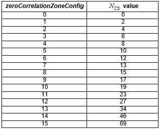
The reason for the indirection is that Ncs means different things in different formats. It is a cyclic shift measured in samples of the preamble sequence, so the same shift covers a different round trip distance at 1.25 kHz than it does at 15 kHz. A single number sent over the air would not survive that change.
The count of preambles per root sequence follows from it directly. A sequence of length LRA divided by Ncs gives how many distinct shifts fit, and each shift is one usable preamble. A small Ncs therefore yields many preambles from one root and a small cell, and a large Ncs yields few preambles and a large cell.
zeroCorrelationZoneConfig is an index, not a value : it runs from 0 to 15 and selects a row, and the row is chosen by preamble format and restricted set type.Ncs sets the cell radius : the shift has to exceed the round trip delay of the furthest UE, or two UEs at different distances become indistinguishable.It also sets how many preambles a root sequence yields : LRA divided by Ncs, so radius and preamble count trade directly against each other.Restricted sets exist for high speed : Type A and Type B remove the shifts that Doppler would make ambiguous, which is why the tables split by restricted set.
Root Sequence Index
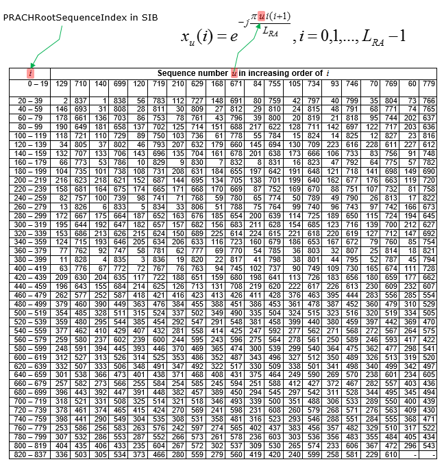
Like LTE Root Sequence Index, NR use different numbering system at RRC layer and Physical Layer for Root Sequence Index and the mapping between these two are defined as in following tables.
< 38.211-Table 6.3.3.1-3: Mapping from PRACHRootSequenceIndex i to sequence number u for preamble formats with L_RA = 839 >
< 38.211-Table 6.3.3.1-4: Mapping from PRACHRootSequenceIndex i to sequence number u for preamble formats with L_RA = 139 >
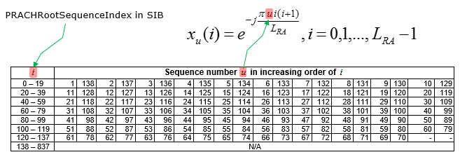
The two tables exist because the numbering the network sends is not the numbering the physical layer uses. RRC carries prach-RootSequenceIndex, a logical index, and 38.211 maps it to the sequence number u that actually generates the Zadoff-Chu sequence. The mapping is a permutation rather than an offset, so it cannot be computed and has to be looked up.
Which of the two tables applies is decided by sequence length. Table 6.3.3.1-3 covers LRA = 839, the long sequence formats, and Table 6.3.3.1-4 covers LRA = 139, the short ones. The RACH-ConfigCommon listing below reflects that split, because prach-RootSequenceIndex is a CHOICE between l839 and l139.
Logical and physical indices differ : RRC sends a logical index, and the physical layer needs the sequence number u, so a table stands between them.The ordering is deliberate : consecutive logical indices map to sequences chosen to keep cross correlation low, which is why the mapping cannot be an arithmetic offset.Length selects the table : 839 uses Table 6.3.3.1-3 and 139 uses Table 6.3.3.1-4, matching the l839 and l139 arms of prach-RootSequenceIndex.One root is rarely enough : when Ncs is large the shifts run out quickly, and the cell has to take the next root sequence to reach 64 preambles.
Long vs Short Sequences
In LTE, only one type of sequence length is used (format length varies in LTE as well, but the length of the building block sequence is always same), in NR there are two types of sequence length called Long and Short Sequence are used.
Followings would be a good summary about the design concept and application of the long and short sequence. (this is from III-B of this paper )
- The short preamble formats can be used in both FR1 with subcarrier spacing of 15 or 30 kHz and FR2 with subcarrier spacing of 60 or 120 kHz.
- In contrast to LTE, for the design of the short preamble formats, the last part of each OFDM symbol acts as a CP for the next OFDM symbol and the length of a preamble OFDM symbol equals the length of data OFDM symbols.
- Benefits of Short Sequence :
- Firstly, it allows the gNB receiver to use the same fast Fourier transform (FFT) for data and random-access preamble detection.
- Secondly, due to the composition of multiple shorter OFDM symbols per PRACH preamble, the new short preamble formats are more robust against time varying channels and frequency errors.
- Thirdly, it supports the possibility of analog beam sweeping during PRACH reception such that the same preamble can be received with different beams at the gNB.
Preamble Format
NR also use various types of Preamble Format as shown below. You would notice that NR PRACH preamble format is much more diverse than LTE Preamble Format.
As you see in the following tables, two different length (L_RA) of PRACH preamble is used depending on subcarrier spacing of the preamble.
< Long Sequence >
When the subcarrier spacing of PRACH preamble is 1.25 or 5 Khz, long sequence (L_RA = 839) is used as in the following table. (NOTE : Regarding 'Restricted sets', refer to zeroCorrelationZoneConfig and Ncs)
< 38.211 - Table 6.3.3.1-1: PRACH preamble formats for  and
and  >
>

These long sequence is used only in a specific configuration for FR1. Subcarrier spacing for this configuration applies only for msg1 (PRACH).
|
Format |
msg1 Subcarrier Spacing |
Table |
ConfigurationIndex |
|
0 |
1.25 Khz |
0-27 |
|
|
0-27 |
|||
|
1 |
1.25 Khz |
28-52 |
|
|
28-33 |
|||
|
2 |
1.25 Khz |
53-59 |
|
|
34-39 |
|||
|
3 |
5 Khz |
60-86 |
|
|
40-66 |
< Short Sequence >
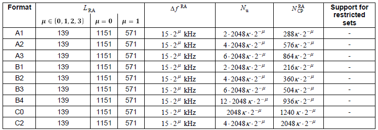
When the subcarrier spacing of PRACH preamble is 15,30,60 or 120 Khz, short sequence (L_RA = 139) is used as in the following table. (NOTE : Regarding 'Restricted sets', refer to zeroCorrelationZoneConfig and Ncs)
< 38.211 - Table 6.3.3.1-2: Preamble formats for  and
and  where
where  >
>

< Frequency Bandwidth for PRACH Subcarrier Spacing >
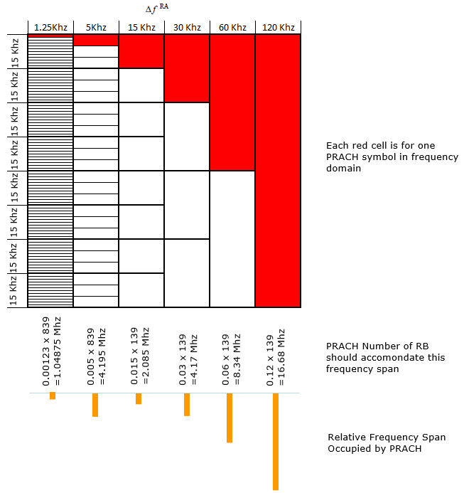
Preamble length and subcarrier spacing together decide how much bandwidth a preamble occupies, and the two do not move independently. A long sequence at narrow spacing and a short sequence at wide spacing can land on a similar span, which is what the illustration below sets out.
Following illustration shows the frequency span occupied by PRACH preamble.
< Time Domain Structure of Preamble Format >
Following is the overall picture of all RACH preamble (as per Rel 15 specification) in time domain. Just pay attention to relative length differences among different types.
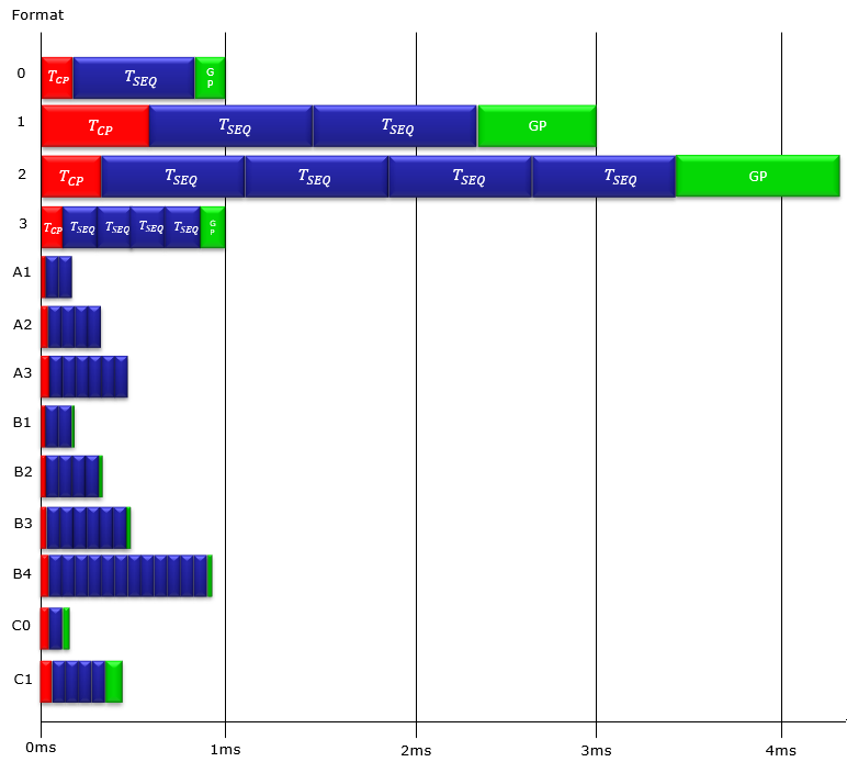
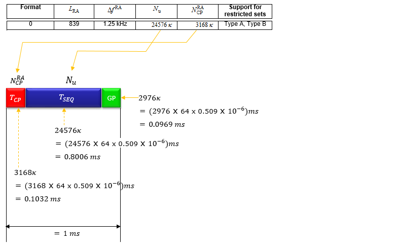
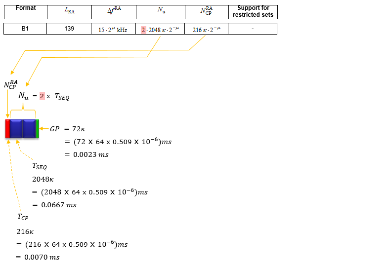
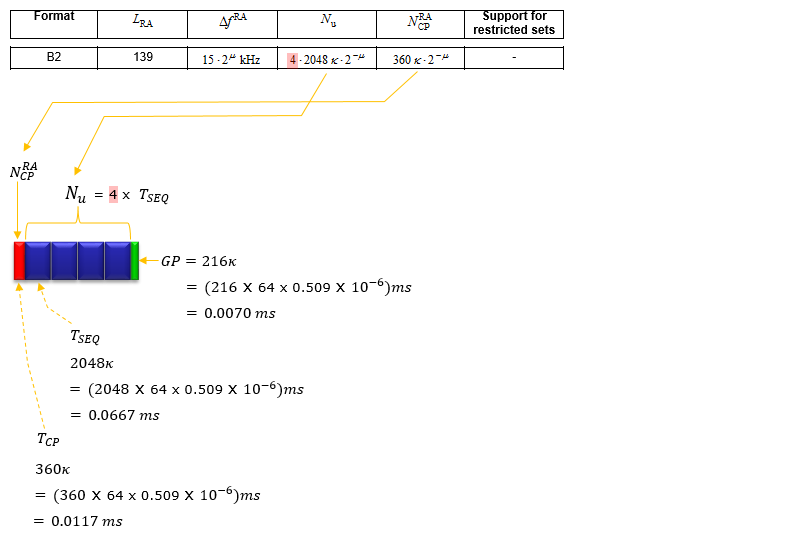
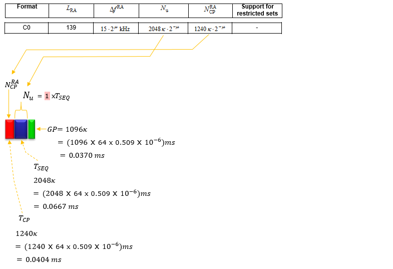
Followings are the illustration of RACH Preamble Time domain structure. GP(GAP) length in this illustration are from Ref 36. The number 0.509 ns(0.509 x 10^-6 ms) is the value of the parameter Tc and 64 is the value of the paramter K(Kappa).
< PRACH Cell Dimensioning >
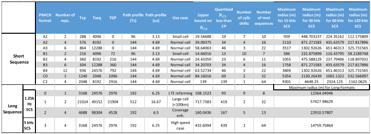
As in LTE, the main reason for why we have so many different types of PRACH Preamble is to provide the best preamble format for vardious cell radius. Following is the table showing the use case of each Preamble format for various cell dimension. This table is from the paper : Table 2 of On the Design Details of SS PBCH Signal Generation and PRACH in 5G-NR
< Preamble Format 0 >
Format 0 is the baseline long sequence. It uses LRA = 839 at 1.25 kHz spacing, one sequence repetition, and it fills exactly 1 ms. The 3168κ cyclic prefix is about 0.10 ms, and that length is what bounds the cell radius.
< Preamble Format 1 >
Format 1 keeps the same 839 sequence and the same 1.25 kHz spacing, but it repeats the sequence twice and stretches the cyclic prefix to 21024κ. That is 0.6849 ms of prefix, and the whole preamble occupies 3 ms.

< Preamble Format 2 >
Format 2 repeats the 839 sequence four times, which buys coverage through accumulation rather than through a long prefix. Its cyclic prefix is 4688κ, shorter than Format 1, and the preamble occupies 4.3 ms.

< Preamble Format 3 >
Format 3 is the only long sequence format at 5 kHz rather than 1.25 kHz. Four repetitions of a 6144κ sequence and a 3168κ prefix fit the same 1 ms as Format 0, and the wider spacing tolerates four times the frequency offset.

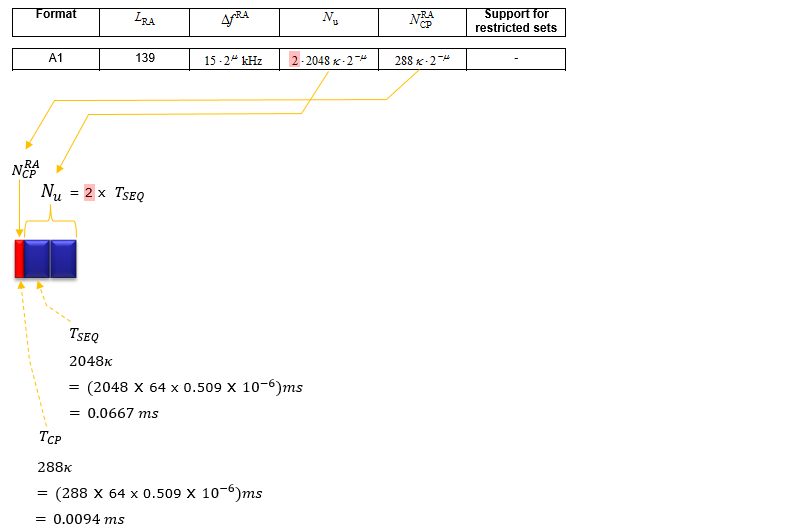
Following illustration shows the short sequence A,B,C. The length calculated here is based on 15 Khz frequency(u=0) interval. As this interval goes higher (e.g, 30, 60, 120, 240 Khz), the length gets shorter.
< Preamble Format A1 >
Format A1 opens the short sequence family. LRA drops to 139, the spacing follows the numerology as 15·2μ kHz, and two repetitions sit behind a 288κ prefix. No guard period follows, which is what distinguishes the whole A family.
< Preamble Format A2 >
Format A2 doubles A1 to four repetitions and its cyclic prefix to 576κ. It ends without a guard period like the rest of the A family, so whatever occupies the next symbol has to start immediately.

< Preamble Format A3 >
Format A3 carries six repetitions behind an 864κ prefix, the longest prefix in the A family. Read the printed result rather than the expression beneath it: 0.0281 ms is the value for 864κ, while the expression on that line still reads 576.

< Preamble Format B1 >
Format B1 is A1 with a guard period added. The sequence count and the 139 length are unchanged, the cyclic prefix drops to 216κ, and 72κ of guard period appears at the end, which is 0.0023 ms.
< Preamble Format B2 >
Format B2 carries four repetitions with a 360κ prefix and a 216κ guard period. Set it against A2, which has the same repetition count and no guard period at all, and the trade the B family makes becomes visible.
< Preamble Format B3 >
Format B3 carries six repetitions with a 504κ prefix and a 360κ guard period. It is the B family counterpart of A3, and across B1 to B4 the guard period grows with the repetition count.

< Preamble Format B4 >
Format B4 is the longest short sequence format. Twelve repetitions sit behind a 936κ prefix with a 792κ guard period, and twelve is the largest repetition count of any format on this page.

< Preamble Format C0 >
Format C0 inverts the usual proportion between prefix and sequence. One repetition sits behind a 1240κ cyclic prefix, so the prefix is more than half the length of the sequence, and 1096κ of guard period follows it.
< Preamble Format C2 >
Format C2 takes that further. Its cyclic prefix is 2048κ, exactly one sequence length, and its 2912κ guard period is the largest of the short sequence formats. Four repetitions follow the prefix.

L1 Processing Time Line for PRACH
PRACH processing is should be done very accurately and in very limited time frame at fractions of a slot. so it is very important to design carefully about the PRACH reception, processing and convey the result to higher layer. The specific time line for each detailed step is not defined in 3GPP and it is upto implementation. 3GPP outlines only high level timing requirement like :
- At which time (i.e, subframe, slot, symbols) that eNB/gNB expect PRACH (based on PRACH configuration index)
- The maximum time window during which eNB/gNB transmit the respose to the received PRACH
The L1 processing timeline for PRACH is a sequence of carefully coordinated steps that enable a UE to establish initial communication with a base station. By transmitting a preamble, receiving a response, and adjusting timing, the UE achieves uplink synchronization, allowing for further data transmission and network access. This process is essential for the efficient operation of LTE and 5G networks, ensuring that devices can connect and communicate effectively.
The contetns in this section is an example of processing time line at L1 (Layer 1) level. I said 'an example' because these time line is not defined in 3GPP and it is implementation specific. But it will be very useful to get some understanding at this level.
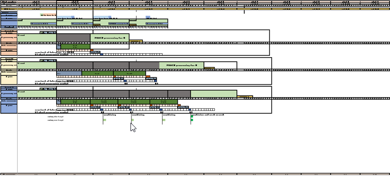
The timing diagram and description is kindly contribued by HANUMANTHAPPA SH . The original diagram is well illustrated in excel spreadsheet, but it is a little too wide to show the entire span of illustration in this note as an image. It is recommended to refer to this orignal spreadsheet for looking into the detailed diagram.
The descriptions below came from Hanumanth.
Below diagram explains wrt PRACH format 0/1/2 L1-L2- RadioInterface timing diagram..
- Time L1 recieve the configuration L2
- radio processing time and
- L1 processing time and time at which sending PHY indication to l2.
< Overall UL processing >
The timeline below is read against one reference slot, called N, which is the slot the radio is on the air with. Everything else is placed relative to it, so a negative offset is preparation and a positive one is processing that has not finished yet.
As an example, let us consider N slot is OTA slot radio is processing.
- with respect to DL : L1 receives configuration from L2 at N-1 and send C plane msg and UL plane msg at T1a_max cp/up time to Radio.
- with respect to UL : L1 receives configuration from L2 at N-1 and send C plane msg at T1a_max UL CP time to Radio and later l1 receive the every symbol from radio with Ta4_max time difference sending indiaction to l2 in next splot after L1 processing complete.
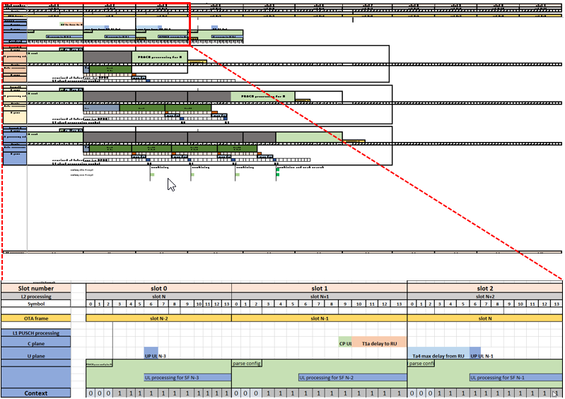
Following is the description on each component of the timeline
-
L1 PUSCH processing: L1 processing processing time for PUSCH channel.. i.e l1 processing includes processing of channel estimation/equalization.. demod/deinterleave/descramble and FEC/cb/tb/crc check and preparing msg for sending indication to mac.
-
Cplane: this is an example for symbol where uplink C plane msg is prepare and sending to RU..
-
Uplane: this is an example for symbol where uplink U plane msg is start receiving from RU and copying into L1 buffers..
-
Context: this is context used in l1 as ping pong buffer etc.
< PRACH format 0 >
The three timelines that follow differ in one number, and it is the slot at which L1 hands its result up to L2. Format 0 fits inside a single slot, so processing completes at n+1 and the indication goes up at the start of N+2.
- L1 receives configuration from L2 at N-1 and send C plane msg at T1a_max UL CP time to Radio and l1 receive the symbol from radio at slot Nth boundary with Ta4_max time.
- L1 processing it at n+1 slot and sending indiaction to l2 at N+2 start of the slot.
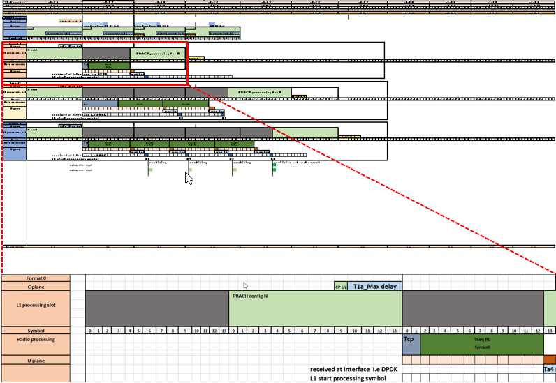
Following is the description on each component of the timeline
- L1 processing slot: L1 processing processing time for PRACH channel.. i.e l1 processing includes processing of prach IQ's.. correlation with ref seq/time doamin convert/AGC/IQ Combining/PeakSearch etc and preparing msg for sending indication to mac.
- Cplane: this is an example for symbol where uplink C plane msg is prepare and sending to RU..
- Radio processing : processing time for radio..
- Uplane: this is an example for symbol where uplink U plane msg is start receiving from RU and copying into L1 buffers.
< PRACH format 1 >
Format 1 spans more symbols than format 0, so L1 cannot finish within the same slot. Processing completes at n+2 instead, and the indication reaches L2 at the start of N+3, one slot later than the format above.
- L1 receives configuration from L2 at N-1 and send C plane msg at T1a_max UL CP time to Radio and L1 receive the each symbol from radio at duration of 800usec with Ta4_max time.
- L1 receive the all the symbols and process at n+2 slot and sending indiaction to l2 at N+3 start of the slot.
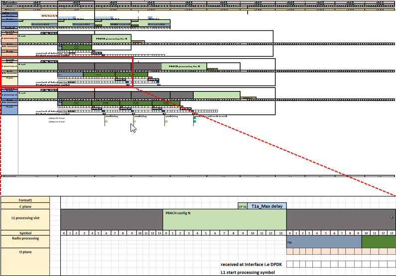
Following is the description on each component of the timeline
- L1 processing slot: L1 processing processing time for PRACH channel.. i.e l1 processing includes processing of prach IQ's.. correlation with ref seq/time doamin convert/AGC/IQ Combining/PeakSearch etc and preparing msg for sending indication to mac.
- Cplane: this is an example for symbol where uplink C plane msg is prepare and sending to RU..
- Radio processing : processing time for radio..
- Uplane: this is an example for symbol where uplink U plane msg is start receiving from RU and copying into L1 buffers.
< PRACH format 2 >
Format 2 is the longest of the three, and the cost shows at the end of the chain. L1 completes at n+4 and the indication reaches L2 at the start of N+5, three slots later than format 0.
- L1 receives configuration from L2 at N-1 and send C plane msg at T1a_max UL CP time to Radio and L1 receive the each symbol from radio at duration of 800usec with Ta4_max time.
- L1 receive the all the symbols and process at n+4 slot and sending indication to L2 at N+5 start of the slot.
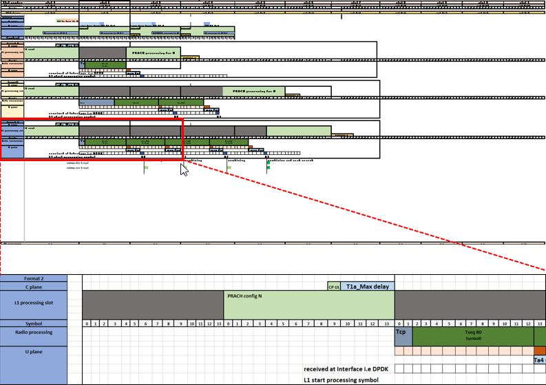
Following is the description on each component of the timeline
- L1 processing slot: L1 processing processing time for PRACH channel.. i.e l1 processing includes processing of prach IQ's.. correlation with ref seq/time doamin convert/AGC/IQ Combining/PeakSearch etc and preparing msg for sending indication to mac.
- Cplane: this is an example for symbol where uplink C plane msg is prepare and sending to RU..
- Radio processing : processing time for radio..
- Uplane: this is an example for symbol where uplink U plane msg is start receiving from RU and copying into L1 buffers.
Random Access Configuration
As in LTE, NR Random Access Configuration is the parameter that determine when (i.e, which radio frame and which subframe) UE is allowed to transmit PRACH Preamble and what kind of Preamble format it should transmit. If you are familiar with the interpretation of LTE RACH configuration table , you would easily understand this table as well. Except n_SFN mod x = y part, everything is same as in LTE case.
< 38.211 v15.5.0-Table 6.3.3.2-2: Random access configurations for FR1 and paired spectrum/supplementary uplink >

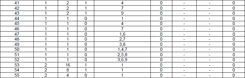

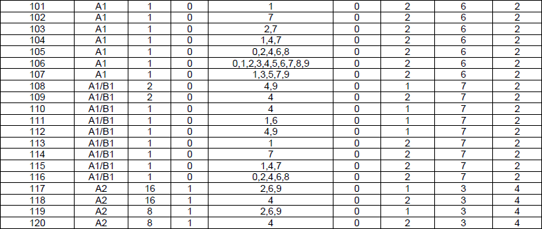
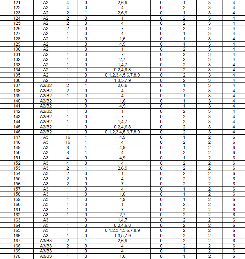
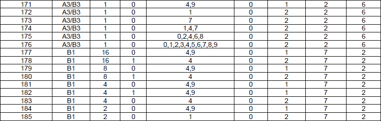

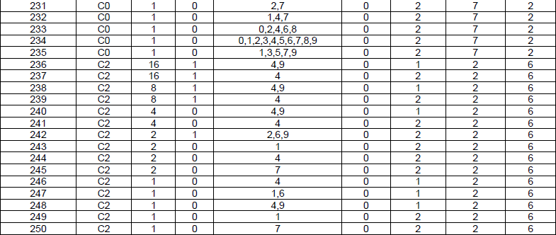

Just for clarity, let me give you a couple of examples.
Example 1 > PRACH Configuration Index = 0
In this case, x is 16 and y = 1. It means UE is allowed to transmit PRACH in every odd radio frame (i.e, the radio frame meeting n_SFN mod 16 = 1). UE is allowed to transmit the PRACH at SFN = 1, 17, 33, ....
In this case, Subframe number is set to 1. It means that UE can transmit PRACH at the subframe 1 within the radio frame determined as above.
Example 2 > PRACH Configuration Index = 27
In this case, x = 1 and y = 0. It means UE is allowed to transmit PRACH in radio frame (i.e, the radio frame meeting n_SFN mod 1 = 0). UE is allowed to transmit at every SFN.
In this case, Subframe number is set to 0,1,2,3,4,5,6,7,8,9. It means that UE can transmit PRACH at any subframe within the radio frame determined as above.
< 38.211 v15.3.0-Table 6.3.3.2-3: Random access configurations for FR1 and unpaired spectrum >
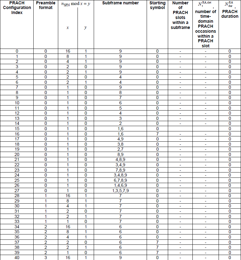

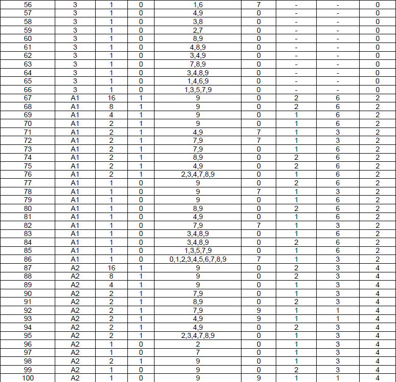
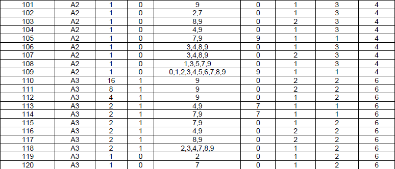
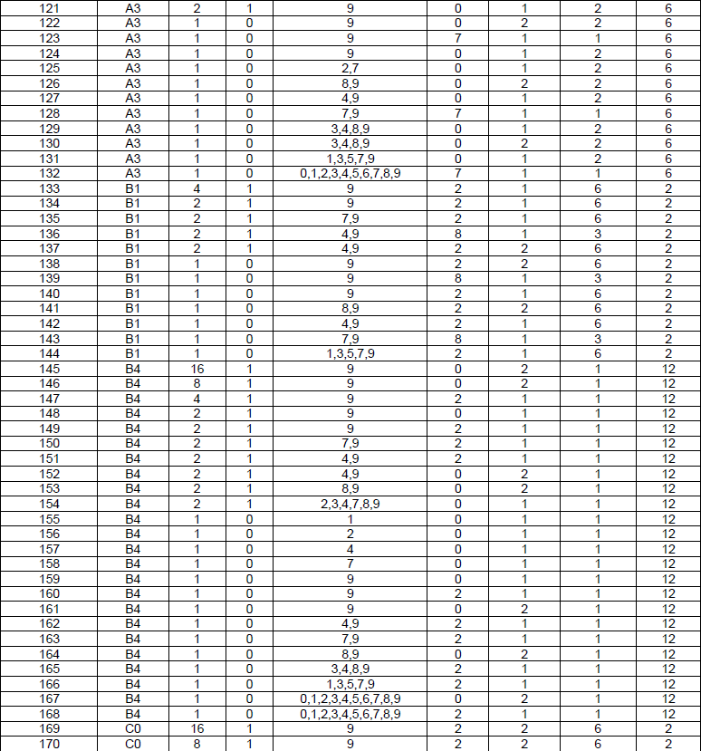

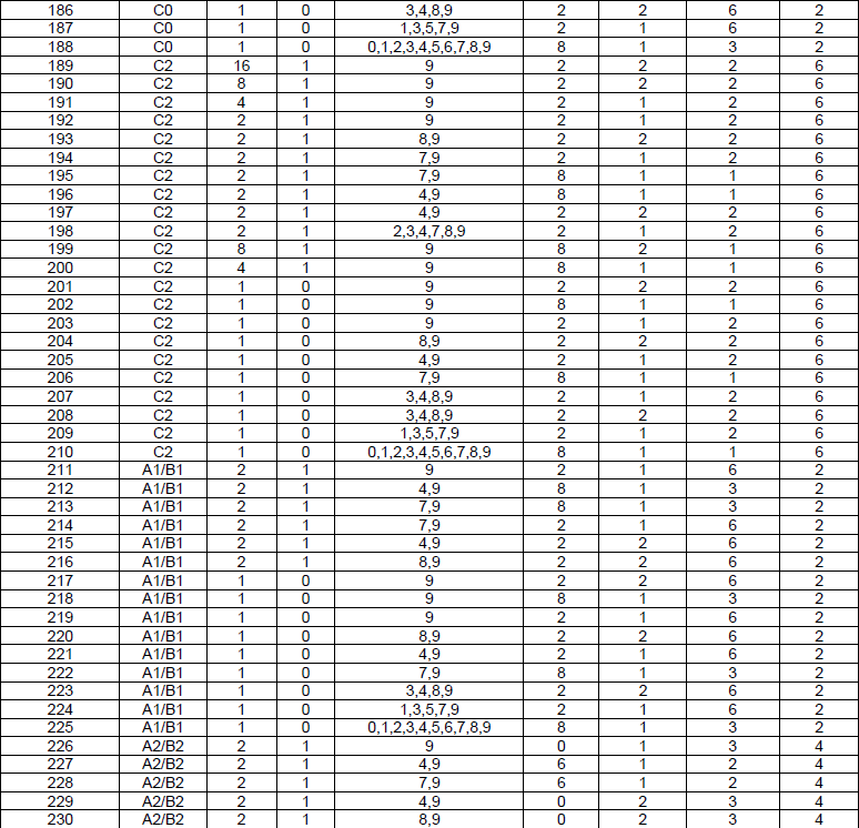


New configuration added at Release 16.

< 38.211 v15.3.0-Table 6.3.3.2-4: Random access configurations for FR2 and unpaired spectrum >
NOTE : I wrote a visualized version of this table using Matlab 5G Toolbox here.
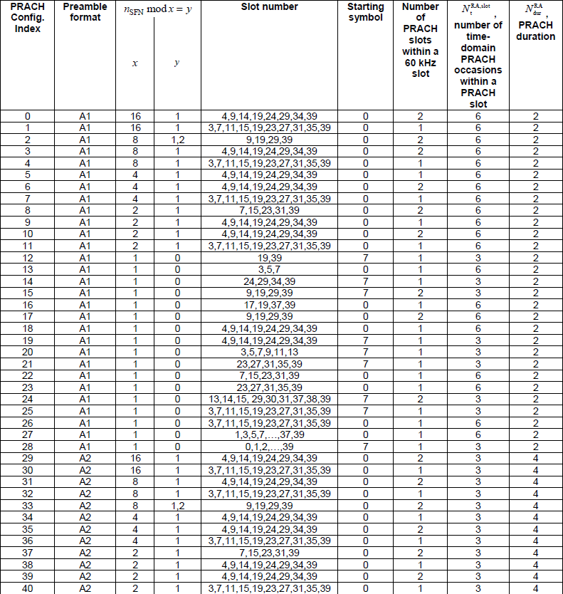
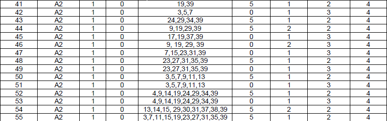
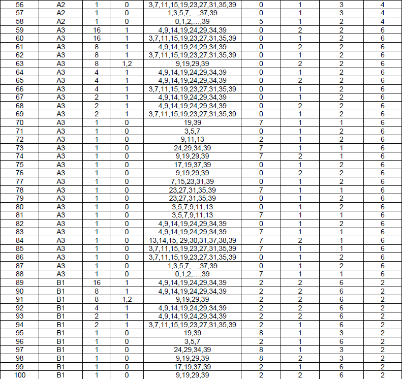
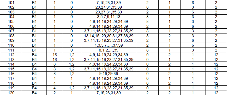
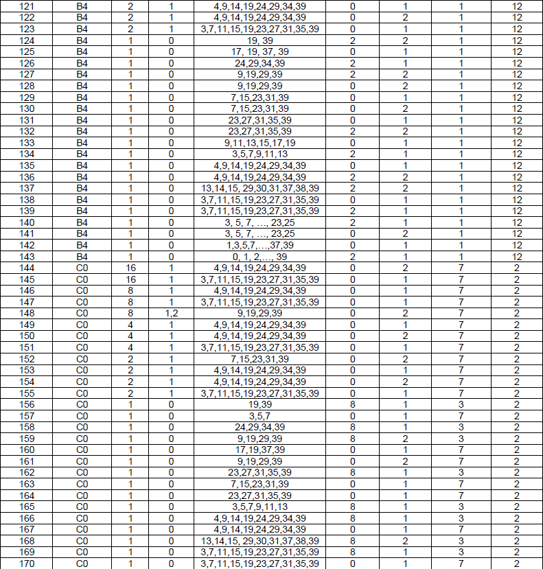
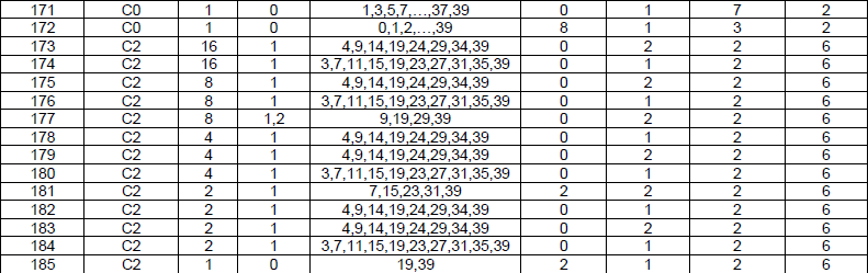
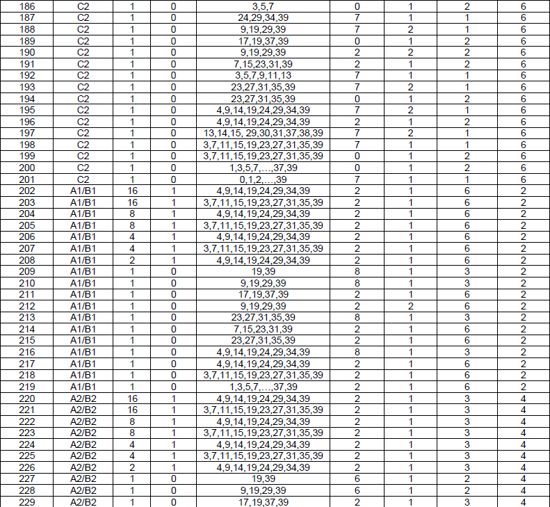
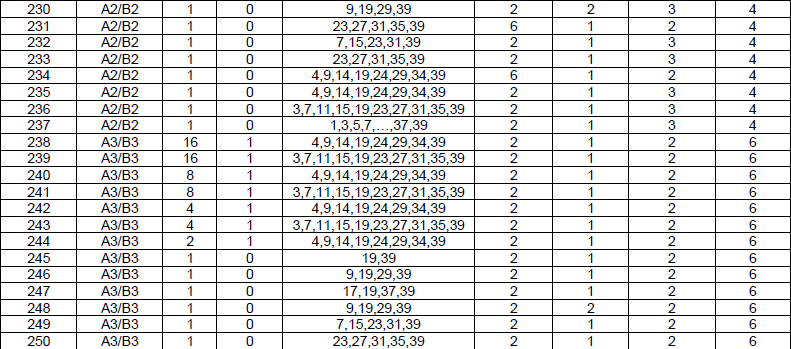

RRC Parameters for RACH Process
The listings below are the RRC that drives everything above. RACH-ConfigCommon is broadcast and applies to every UE in the cell. RACH-ConfigDedicated is sent to one UE and carries the contention free resources, and RACH-ConfigGeneric holds the parameters both of them share.
|
Parameter (IE) |
Description |
Reference |
|
prach-ConfigurationIndex |
38.321-5.1 | |
| 38.211-6.3.3 | ||
| 38.211-6.3.3 | ||
| 38.211-6.3.3 | ||
| PreambleInitialReceivedTargetPower |
initial preamble power |
38.321-5.1.3 |
| rsrp-ThresholdSSB | ||
| csirs-dedicatedRACH-Threshold | ||
| sul-RSRP-Threshold | ||
| ssb-Threshold | ||
|
powerRampingStep |
38.321-5.1 | |
| ra-PreambleIndex | ||
|
PreambleTransMax |
38.321-5.1 | |
|
ra-Msg3SizeGroupA |
38.321-5.1 | |
|
messagePowerOffsetGroupB |
||
|
ra-ResponseWindowSize |
38.321-5.1 | |
|
ra-ContentionResolutionTimer |
38.321-5.1 | |
|
PreambleStartIndex |
38.321-5.1 | |
|
NumberofRA-Preambles |
||
|
zeroCorrelationZoneConfig |
38.211-6.3.3 | |
|
ra-ResponseWindow |
||
|
rach-ControlResourceSet |
||
|
msg3-transformPrecoding |
Msg3 Transform Precoding | 38.213-8.3 |
|
msg3-SubcarrierSpacing |
Msg3 Subcarrier Spacing | 38.213-8.3 |
Followings are based on 38.331 v16.3.0
Following is based on
RACH-ConfigCommon ::=               SEQUENCE {
    rach-ConfigGeneric                  RACH-ConfigGeneric,
    totalNumberOfRA-Preambles           INTEGER (1..63)                                                     OPTIONAL,   -- Need S
    ssb-perRACH-OccasionAndCB-PreamblesPerSSB   CHOICE {
        oneEighth                                   ENUMERATED {n4,n8,n12,n16,n20,n24,n28,n32,n36,n40,n44,n48,n52,n56,n60,n64},
        oneFourth                                   ENUMERATED {n4,n8,n12,n16,n20,n24,n28,n32,n36,n40,n44,n48,n52,n56,n60,n64},
        oneHalf                                     ENUMERATED {n4,n8,n12,n16,n20,n24,n28,n32,n36,n40,n44,n48,n52,n56,n60,n64},
        one                                         ENUMERATED {n4,n8,n12,n16,n20,n24,n28,n32,n36,n40,n44,n48,n52,n56,n60,n64},
        two                                         ENUMERATED {n4,n8,n12,n16,n20,n24,n28,n32},
        four                                        INTEGER (1..16),
        eight                                       INTEGER (1..8),
        sixteen                                     INTEGER (1..4)
    }                                                                                                       OPTIONAL,   -- Need M
    groupBconfigured                    SEQUENCE {
        ra-Msg3SizeGroupA                   ENUMERATED {b56, b144, b208, b256, b282, b480, b640,
                                                        b800, b1000, b72, spare6, spare5,spare4, spare3, spare2, spare1},
        messagePowerOffsetGroupB            ENUMERATED { minusinfinity, dB0, dB5, dB8, dB10, dB12, dB15, dB18},
        numberOfRA-PreamblesGroupA          INTEGER (1..64)
    }                                                                                                       OPTIONAL,   -- Need R
    ra-ContentionResolutionTimer            ENUMERATED { sf8, sf16, sf24, sf32, sf40, sf48, sf56, sf64},
    rsrp-ThresholdSSB                       RSRP-Range                                                      OPTIONAL,   -- Need R
    rsrp-ThresholdSSB-SUL                   RSRP-Range                                                      OPTIONAL,   -- Cond SUL
    prach-RootSequenceIndex                 CHOICE {
        l839                                    INTEGER (0..837),
        l139                                    INTEGER (0..137)
    },
    msg1-SubcarrierSpacing                  SubcarrierSpacing                                               OPTIONAL,   -- Cond L139
    restrictedSetConfig                     ENUMERATED {unrestrictedSet, restrictedSetTypeA, restrictedSetTypeB},
    msg3-transformPrecoder                  ENUMERATED {enabled}                                            OPTIONAL,   -- Need R
    ...,
    [[
    ra-PrioritizationForAccessIdentity-r16  SEQUENCE {
        ra-Prioritization-r16                   RA-Prioritization,
        ra-PrioritizationForAI-r16              BIT STRING (SIZE (2))
    }                                                                                                       OPTIONAL,   -- Cond InitialBWP-Only
    prach-RootSequenceIndex-r16             CHOICE {
        l571                                    INTEGER (0..569),
        l1151                                   INTEGER (0..1149)
    }   OPTIONAL   -- Need R
    ]],
    [[
    ra-PrioritizationForSlicing-r17         RA-PrioritizationForSlicing-r17                          OPTIONAL,   -- Cond InitialBWP-Only
    featureCombinationPreamblesList-r17     SEQUENCE (SIZE(1..maxFeatureCombPreamblesPerRACHResource-r17)) OF FeatureCombinationPreambles-r17 OPTIONAL -- Cond AdditionalRACH
    ]],
    [[
    rach-ConfigAdapt-r19                    RA-AdaptConfig-r19                              OPTIONAL           -- Need R
    ]]
}
Following is based on
RACH-ConfigDedicated ::=        SEQUENCE {
    cfra                            CFRA                                                                    OPTIONAL, -- Need S
    ra-Prioritization               RA-Prioritization                                                       OPTIONAL, -- Need N
    ...,
    [[
    ra-PrioritizationTwoStep-r16    RA-Prioritization                                                       OPTIONAL, -- Need N
    cfra-TwoStep-r16                CFRA-TwoStep-r16                                                        OPTIONAL  -- Need S
    ]]
}
Following is based on
CFRA ::=                    SEQUENCE {
    occasions                       SEQUENCE {
        rach-ConfigGeneric              RACH-ConfigGeneric,
        ssb-perRACH-Occasion            ENUMERATED {oneEighth, oneFourth, oneHalf, one, two, four, eight, sixteen}
                                                                                                            OPTIONAL  -- Cond Mandatory
    }                                                                                                       OPTIONAL, -- Need S
    resources                       CHOICE {
        ssb                             SEQUENCE {
            ssb-ResourceList                SEQUENCE (SIZE(1..maxRA-SSB-Resources)) OF CFRA-SSB-Resource,
            ra-ssb-OccasionMaskIndex        INTEGER (0..15)
        },
        csirs                           SEQUENCE {
            csirs-ResourceList              SEQUENCE (SIZE(1..maxRA-CSIRS-Resources)) OF CFRA-CSIRS-Resource,
            rsrp-ThresholdCSI-RS            RSRP-Range
        }
    },
    ...,
    [[
    totalNumberOfRA-Preambles INTEGER (1..63)                                                             OPTIONAL -- Cond Occasions
    ]],
    [[
    msg1-RepetitionNum-r18          ENUMERATED {n2, n4, n8, spare1}                                        OPTIONAL -- Cond 4StepCFRArep
    ]],
    [[
    ra-OccasionType-r19             ENUMERATED {sbfd}                                                      OPTIONAL  -- Need S
    ]]
}
Following is based on
CFRA-TwoStep-r16 ::=                    SEQUENCE {
    occasionsTwoStepRA-r16                  SEQUENCE {
        rach-ConfigGenericTwoStepRA-r16         RACH-ConfigGenericTwoStepRA-r16,
        ssb-PerRACH-OccasionTwoStepRA-r16       ENUMERATED {oneEighth, oneFourth, oneHalf, one,
                                                            two, four, eight, sixteen}
    }                                                                                                     OPTIONAL, -- Need S
    msgA-CFRA-PUSCH-r16                     MsgA-PUSCH-Resource-r16,
    msgA-TransMax-r16                       ENUMERATED {n1, n2, n4, n6, n8, n10, n20, n50, n100, n200}    OPTIONAL, -- Need S
    resourcesTwoStep-r16                    SEQUENCE {
        ssb-ResourceList                        SEQUENCE (SIZE(1..maxRA-SSB-Resources)) OF CFRA-SSB-Resource,
        ra-ssb-OccasionMaskIndex                INTEGER (0..15)
    },
    ...
}
Following is based on
CFRA-SSB-Resource ::=           SEQUENCE {
    ssb                             SSB-Index,
    ra-PreambleIndex                INTEGER (0..63),
    ...,
    [[
    msgA-PUSCH-Resource-Index-r16   INTEGER (0..3071)     OPTIONAL  -- Cond 2StepCFRA
    ]]
}
Following is based on
CFRA-CSIRS-Resource ::=         SEQUENCE {
    csi-RS                          CSI-RS-Index,
    ra-OccasionList                 SEQUENCE (SIZE(1..maxRA-OccasionsPerCSIRS)) OF INTEGER (0..maxRA-Occasions-1),
    ra-PreambleIndex                INTEGER (0..63),
    ...
}
Following is based on
RACH-ConfigGeneric ::=              SEQUENCE {
    prach-ConfigurationIndex            INTEGER (0..255),
    msg1-FDM                            ENUMERATED {one, two, four, eight},
    msg1-FrequencyStart                 INTEGER (0..maxNrofPhysicalResourceBlocks-1),
    zeroCorrelationZoneConfig           INTEGER(0..15),
    preambleReceivedTargetPower         INTEGER (-202..-60),
    preambleTransMax                    ENUMERATED {n3, n4, n5, n6, n7, n8, n10, n20, n50, n100, n200},
    powerRampingStep                    ENUMERATED {dB0, dB2, dB4, dB6},
    ra-ResponseWindow                   ENUMERATED {sl1, sl2, sl4, sl8, sl10, sl20, sl40, sl80},
    ...,
    [[
    prach-ConfigurationPeriodScaling-IAB-r16    ENUMERATED {scf1,scf2,scf4,scf8,scf16,scf32,scf64}              OPTIONAL,   -- Need R
    prach-ConfigurationFrameOffset-IAB-r16      INTEGER (0..63)                                                 OPTIONAL,   -- Need R
    prach-ConfigurationSOffset-IAB-r16          INTEGER (0..39)                                                 OPTIONAL,   -- Need R
    ra-ResponseWindow-v1610                     ENUMERATED { sl60, sl160}                                       OPTIONAL,   -- Need R
    prach-ConfigurationIndex-v1610              INTEGER (256..262)                                              OPTIONAL    -- Need R
    ]],
    [[
    ra-ResponseWindow-v1700                     ENUMERATED {sl240, sl320, sl640, sl960, sl1280, sl1920, sl2560} OPTIONAL    -- Need R
    ]],
    [[
    sbfd-RACH-SingleConfig-preambleReceivedTargetPower-r19     INTEGER (-202..-60)                              OPTIONAL    -- Need R
    ]]
}
RACH Procedure for Initial Attach
According to 38.321, I noticed that NR RACH process is very similar to LTE RACH procedure. Of course, there will be small differences in terms of the detailed parameters but overall procedure is almost same. Actually the overall procedure for LTE RACH, LTE BL/CE(M1) RACH, LTE NB RACH and NR RACH are almost same even though there are minor differences in the parameters. I personally recommend you to read through all of these RACH pages. If you read all of these RACH pages for LTE, M1, M2, NR, you will gradually get your own intuitive understandings on RACH procedure (Don't try to memorize these sequence, just read through several times whenever you have time and the overall sequence will automatically be imprinted in your brain).
In following sequence, I put the steps labelled as (A)~(J) and steps as (1)~(9). The steps (A)~(J) is the specific messages being transmitted by gNB and UE. The steps (1)~(9) are internal procedure in UE and gNB that are required to transmit or receive the message.
I will complete the detailed description once RRC specification for this part is finalized.

With the completion of these two steps, UE should be able to get all the information as follows (based on 38.213-8 Random Access Procedure)
- Configuration of PRACH transmission Parameters
- PRACH Preamble Format
- Time Resources
- Frequency Resources
- Parameters for determining the root sequences and their cyclic shifts in the PRACH Preamble sequence set
- index to logical root sequence table
- Cyclic Shift(Ncs)
- Set Type (unrestricted, restricted set A or restricted set B)
At this step, UE transmit PRACH Preamble with RA-RNTI if all the condition for PRACH transmission is met. RA-RNTI is calculated by the following equation according to 38.321-5.1.3: (gNB calculate RA-RNTI based on following equation)
RA-RNTI = RA-RNTI= 1 + s_id + 14 t_id + 14 80 f_id + 14 80 8 ul_carrier_id
,s_id : the index of the first OFDM symbol of the specified PRACH (0 <= s_id < 14)
,t_id : the index of the first slot symbol of the specified PRACH in a system frame (0 <= t_id < 80)
,f_id : the index of the the specified PRACH in the frequency domain(0 <= s_id < 8)
,ul_carrier_id : UL carrier used for Msg1 transmission (0 = normal carrier, 1 = SUL carrier)
- Frequency domain location (resource) for PRACH Preamle is determined by the RRC parameter msg1-FDM and msg1-FrequencyStart
- Time domain location (resource) for PRACH Preamle is determined by the RRC parameter prach-ConfigurationIndex (For the details of prach-Configuration index, refer to RACH Configuration section)
At this step (i.e, after PRACH transmission), following procedure will happen (based on 38.213-8.2 Random Access Response)
- gNB sends a DCI scrambled with RA-RNTI value calculated as above.
- UE tries to detect a PDCCH (DCI) with the corresponding RA-RNTI within the period of RAR-Window. (Within ra-ResponseWindow, UE looks for DCI in the search space : Type 1 PDCCH Common Search Space)
- DCI format for scheduling RAR PDSCH is DCI format 1_0 with RA RNTI.
- Resource Allocation Type for the Msg2 PDSCH would be Resource Allocation Type 1 (See How to dertermine the Resource Allocation Type ?)
- Frequency Domain Resource Allocation for the PDSCH is specified by DCI format 1_0 with RA RNTI.
- Time Domain Resource Allocation for the PDSCH is specified by DCI format 1_0 with RA RNTIand PDSCH-ConfigCommon.
- The RAR-Window is configured by rar-WindowLength IE in a SIB message
- If UE successfully decoded the PDCCH, it decodes PDSCH carrying RAR data.
- After decoding RAR, UE checked if RAPID in RAR matches the RAPID assigned to the UE.
- This PDCCH and PDSCH should be carried in same subcarrier spacing and cyclic prefix as SIB1.
Following is the data structure of MAC PDU that carries RAR(Random Access Response)
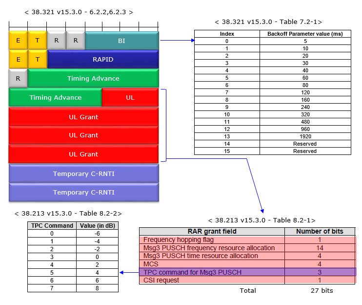
If the UE does not detect the DCI format 1_0 with CRC scrambled by the corresponding RA-RNTI within the window,or if the UE does not correctly receive the transport block in the corresponding PDSCH within the window
At this step (i.e, right before sending Msg3), following things will happen (based on 38.213-8.3 Msg3 PUSCH)
- UE shall determine whether it will apply transform precoding for Msg 3 PUSCH or not, based on the RRC parameter called msg3-tp (msg3-transformPrecoding)
- UE shall determine the subcarrier spacing for Msg3 PUSCH from the RRC parameter called msg3-scs (Subcarrier Spacing).
- UE shall transmit Msg3 PUSCH on the same serving cell to which it sent PRACH
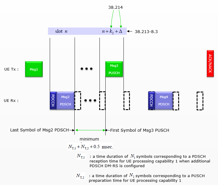
< 38.214 v15.3 -Table 6.1.2.1.1-5: Definition of value Δ >
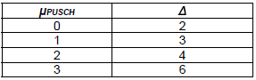
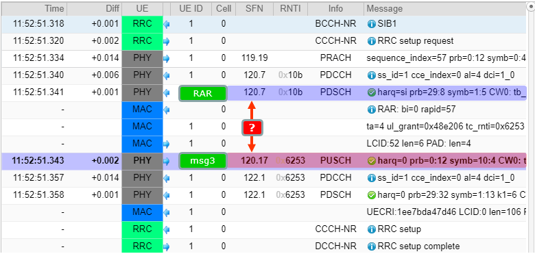
Based on following informations, the time delay between RAR and msg3 PUSCH is k2 + Δ = 7 + 3 = 10 slots. This is same as SFN time stamp in the log which is 120.17[msg3 SFN] - 120.7[RAR SFN] = 10 slots.
[Info 1] Numerology (Subcarrier Spacing)
subcarrierSpacing kHz30
[Info 2] pusch-TimeDomainAllocationList in SIB1
Decoded RRC,
pusch-ConfigCommon setup: {
  pusch-TimeDomainAllocationList {
    {
      k2 6,
      mappingType typeB,
      startSymbolAndLength 41
    },
    {
      k2 6,
      mappingType typeB,
      startSymbolAndLength 52
    },
    {
      k2 7,
      mappingType typeB,
      startSymbolAndLength 52
    }
  },
[Info 3] RAR Timing and Contents : 120.
Message: RAR: bi=0 rapid=57
Data:
bi=0
rapid=57
ta=4
ul_grant:
hopping_flag=0
riv=0x48e
time_domain_rsc=2
mcs=0
tpc_command=3
csi_request=0
tc-rnti=0x6253
[Info 4] msg3 PUSCH Timing and Contents : 120.
PUSCH @ 120.
From: ue01.log #15
Info: ue01.log (1496562B), v2021-06-17
Time: 11:52:51.343
Message: harq=0 prb=0:12 symb=10:4 CW0: tb_len=12 mod=2 rv_idx=0 cr=0.12 retx=0
At this step (i.e, right after sending Msg3), following things will happen (based on 38.321 - 5.1.5). For simplicity, I would describe only on successful case here.
- Start ra-ContentionResolutionTimer
- Monitor to decode PDCCH with TC-RNTI (While ra-ContentionResolutionTimer is running , UE looks for DCI in the search space : Type 1 PDCCH Common Search Space)
- If PDCCH is successfully decoded,
- decode PDSCH carrying the MAC CE
- Set C-RNTI = TC-RNTI
- discard ra-ContentionResolutionTimer
- consider this Random Access Procedure successfully completed
Once UE successfully decode Msg4 (Contention Resolution), UE sends HARQ ACK for the data(PDSCH carrying Msg4).
38.213 - 8.4 states as follows :
In response to the PDSCH reception with the UE contention resolution identity, the UE transmits HARQ-ACK information in a PUCCH. A minimum time between the last symbol of the PDSCH reception
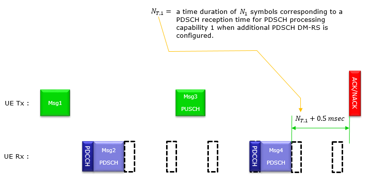
RACH Procedure for LTE-Interworking (ENDC)
This is the process that happens when a LTE cell add NR Cell as a process of Dual Connectivity. Before you go into the details of this process, I would suggest you to read LTE-Interworking page and get some big picture first.
There are two difference options (cases) of the RACH process for ENDC(EUTRA-NR Dual Connectivity) - CBRA(Contention Based RACH) and CFRA(Contention Free RACH) as described below.
< Case 1 > CBRA (Contention Based RACH)
Since this is CBRA, the basic sequence is very similar to the RACH procedure for the initial attach that is described in previous section. Some minor differences comparing to the initial Attach case are as follows.
- UE recieves all the information about Sync and RACH configuration from LTE RRC Connection Reconfiguration instead of MIB/SIB in NR.
- No PDSCH (carrying Contention Resolution MAC CE) is needed for Msg4. A UL Grant(DCI/PDCCH) for PUSCH functions as a kind of CR(Contention Resolution). At first, I felt strange with this step and was wondering where this modification comes from in 3GPP. After some investigation, I think this modification is based on following statements.
- 38-213 "8.4 PDSCH with UE contention resolution identity" states "In response to an Msg3 PUSCH transmission
when a UE has not been provided with a C-RNTI , the UE attempts to detect a PDCCH with a corresponding TC-RNTI scheduling a PDSCH that includes a UE contention resolution identity." => it imply that CBRA for ENDC do not require PDSCH carrying CR MAC CE because C-RNTI has already beed provided to UE via newUE-Identity in SpCellConfig.ReconfigurationWithSync. - 38.321-"5.1.5 Contention Resolution" states
- 38.331-"5.3.5.5.2 Reconfiguration with sync" states
Once Msg3 is transmitted, the MAC entity shall:
...
1> if notification of a reception of a PDCCH transmission is received from lower layers:
2> if the C-RNTI MAC CE was included in Msg3:
3>
...
4> consider this Contention Resolution successful;
The UE shall perform the following actions to execute a reconfiguration with sync.
...
1> apply the value of

< Case 2 > CFRA (Contention Free RACH)
The contention free case removes the ambiguity that Case 1 has to resolve, and it does so by giving the UE its preamble in advance. The sequence below shows where that preamble comes from, and the RRC path on the right is the part to follow first.

RACH Occasion
RACH Occasion is an area specified in time and frequency domain that are available for the reception of RACH preamble. In LTE, there is only one RACH occasion specified by RRC message(SIB2) for all the possible RACH preambles, but in NR story gets more complicated. In NR, the sync signal (SSB) is associated with different beam and UE select a certain beam and send PRACH using that beam. In order for NW to figure out which beam UE has selected, 3GPP defines a specific mapping between SSB and RACH Occasion (RO). By detecing which RO UE send PRACH to, NW can figure out which SSB Beam that UE has selected.
The mapping between SSB and RACH Occasion is defined by the following two RRC parameters.
- msg1-FDM
- ssb-perRACH-OccasionAndCB-PreamblesPerSSB
msg-FDM specifies how many RO are allocated in frequency domain (at the same location in time domain). ssb-perRACH-OccasionAndCB-PreamblesPerSSB specifies how many SSB can be mapped to one RO and how many premable index can be mapped to single SSB.
The overall mapping logic is descried in 38.213 - 8.1 as below.
- First, in increasing order of preamble indexes within a single PRACH occasion
- Second, in increasing order of frequency resource indexes for frequency multiplexed PRACH occasions
- Third, in increasing order of time resource indexes for time multiplexed PRACH occasions within a PRACH slot
- Fourth, in increasing order of indexes for PRACH slots
I don't think we can easily get a big picture of the mapping logic just from this written description. You may get some visualized form of the mapping logic in R1-1801040.
Based on these two documents, I tried to make some examples based on my interpretation (please send me an email if you don't agree with my interpretation).
All four drawings also assume the cell transmits 64 SS/PBCH blocks, which is the FR2 maximum. That assumption is what makes the last occasion RO#63 in the first two examples and RO#127 in the last one. A cell transmitting 8 SSBs would produce the same patterns with the occasion count divided by eight.
Example 01 >
- msg1-FDM = one
- ssb-perRACH-OccasionAndCB-PreamblesPerSSB = one
This is the simplest of the four, and it is the baseline the other three are read against. With msg1-FDM set to one there is nothing to stack in frequency, so the occasions run left to right in time alone. One SSB per occasion then makes the two indices advance together.

The layout is one row : a single RO sits at each point in time, because msg1-FDM = one gives one frequency multiplexed occasion.SSB index tracks RO index : RO#0 carries SSB 0, RO#1 carries SSB 1, and the pattern continues to RO#63 carrying SSB 63.Sixty four occasions are needed : one SSB per occasion means the cell has to provide as many ROs as it has SSBs.The dots are an elision : the drawing skips the middle of the run and picks up again at RO#63.
Example 02 >
- msg1-FDM = two
- ssb-perRACH-OccasionAndCB-PreamblesPerSSB = one
This is the same one SSB per occasion rule with msg1-FDM raised to two, and it is where the ordering rules listed above become visible. Two occasions now sit at the same instant, one above the other in frequency, so the numbering has to choose which of the two comes first.
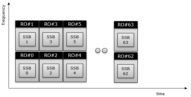
Frequency is exhausted before time : RO#0 is the lower box and RO#1 is the one directly above it, so the index climbs in frequency before it advances in time.That is the second ordering rule : the list above puts frequency resource index ahead of time resource index, and this drawing is what that sentence looks like.The columns advance in pairs : the next time instant carries RO#2 below and RO#3 above, then RO#4 and RO#5.The run still ends at 63 : the last column holds RO#62 with SSB 62 below and RO#63 with SSB 63 above, so sixty four occasions are still needed.
Example 03 >
- msg1-FDM = two
- ssb-perRACH-OccasionAndCB-PreamblesPerSSB = eight
Raising ssb-perRACH-Occasion to eight changes how many occasions the cell needs rather than how they are ordered. Each box now carries a block of eight SSBs, so sixty four SSBs fit into eight occasions instead of sixty four.
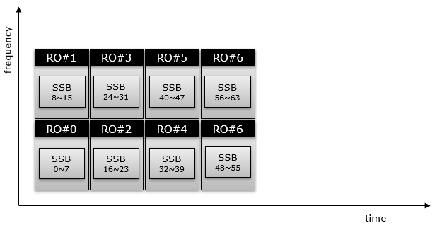
Eight SSBs share one occasion : RO#0 carries SSB 0~7, RO#1 carries SSB 8~15, and the blocks continue in the same frequency first order.Eight occasions cover the whole burst : four time instants, each two deep in frequency, is enough, which is why this drawing has no elision dots.The ordering is unchanged : the lower box of each pair still takes the lower index, exactly as in the drawing above.One label is wrong : the top right box reads RO#6, the same as the box beneath it. Sixty four SSBs at eight per occasion give eight occasions numbered 0 to 7, and SSB 56~63 belongs to RO#7.
Example 04 >
- msg1-FDM = two
- ssb-perRACH-OccasionAndCB-PreamblesPerSSB = oneHalf
A value below one inverts the relationship. Where the drawing above packed several SSBs into one occasion, oneHalf spreads a single SSB across two of them, so the occasion count grows rather than shrinks.
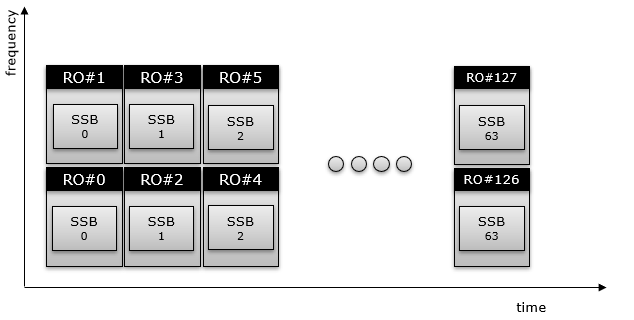
One SSB spans two occasions : RO#0 and RO#1 both carry SSB 0, RO#2 and RO#3 both carry SSB 1, and so on.The occasion count doubles : sixty four SSBs at half an SSB per occasion need 128 occasions, and the drawing ends at RO#126 and RO#127.Both of the last two carry SSB 63 : that is the same pairing seen at the start of the row, applied to the final SSB.More occasions means more preambles for one beam : spreading one SSB over two occasions is how a cell gives a single beam more random access capacity.
RACH Sequence Example 01 > ENDC - CBRA(Contention Based RACH)
The captures below come from one live contention based attempt on an ENDC setup. Read them for the ordering rather than for the values, because a second run of the same procedure produces different identities and different timing.
This is an example of ENDC CBRA captured and shared by Amarisoft. Following is the RACH configuration for this example sequence.
Decoded RRC,
rach-ConfigCommon setup: {
  rach-ConfigGeneric {
    prach-ConfigurationIndex 160, ==> Preamble Format B4
    msg1-FDM one,
    msg1-FrequencyStart 0,
    zeroCorrelationZoneConfig 15,
    preambleReceivedTargetPower -110,
    preambleTransMax n7,
    powerRampingStep dB4,
    ra-ResponseWindow sl20
  },
  ssb-perRACH-OccasionAndCB-PreamblesPerSSB one: n8,
  ra-ContentionResolutionTimer sf64,
  prach-RootSequenceIndex l139: 1,
  msg1-SubcarrierSpacing kHz30,
  restrictedSetConfig unrestrictedSet
},
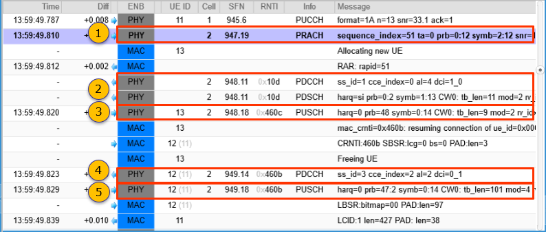
PRACH => Message: sequence_index=51 ta=0 prb=0:12 symb=2:12 snr=15.5
MAC => Message: RAR: rapid=51
PDCCH => Message: ss_id=1 cce_index=0 al=4 dci=1_0
PDSCH => Message: harq=si prb=0:2 symb=1:13 CW0: tb_len=11 mod=2 rv_idx=0 cr=0.19
PUSCH =>
Message: harq=0 prb=48 symb=0:14 CW0: tb_len=9 mod=2 rv_idx=0 cr=0.30 retx=0 crc=OK snr=23.3 epre=-57.4
PDCCH => Message: ss_id=3 cce_index=2 al=2 dci=0_1
PUSCH =>
Message: harq=0 prb=47:2 symb=0:14 CW0: tb_len=101 mod=4 rv_idx=0 cr=0.64 retx=0 crc=OK snr=20.7 epre=-57.3
MAC => Message: LBSR:bitmap=00 PAD:len=97
RACH Sequence Example 02 > ENDC - CBRA(Contention Based RACH)
Following is an example from Amari Callbox from Amarisoft and a commercial UE. You may need a full RrcConnectionReconfiguration message to interpret the detailed contents of the physical channels. Check this for the full RrcConnectionReconfig message.
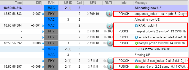
Time: 18:50:56.383
Message: sequence_index=1 ta=4 prb=3:12 symb=2:12 snr=14.4
Log capture. Field values are from a live capture, not from the specification.
Time: 18:50:56.384
Message: RAR: rapid=1

Data:
    rapid=1
    ta=4
    ul_grant:
    hopping_flag=0
    riv=0x2
    time_domain_rsc=2
    mcs=4
    tpc_command=3
    csi_request=0
    tc-rnti=0x4602
Time: 18:50:56.384
Message: harq=si prb=49:2 symb=1:13 CW0: tb_len=11 mod=2 rv_idx=0 cr=0.19
Log capture. Field values are from a live capture, not from the specification.
Time: 18:50:56.384
Message: ss_id=1 cce_index=0 al=4 dci=1_0

Data:
    rb_alloc=0x64
    time_domain_rsc=0
    vrb_to_prb_map=0
    mcs=2
    tb_scaling=0
Time: 18:50:56.392
Message: harq=0 prb=2 symb=0:14 CW0: tb_len=9 mod=2 rv_idx=0 cr=0.30 retx=0
crc=OK snr=7.5 epre=-122.4 ta=-1.0
Log capture. Field values are from a live capture, not from the specification.
Time: 18:50:56.392
Message: ss_id=2 cce_index=0 al=2 dci=0_1 k2=4

Data:
    rb_alloc=0x4c5
    time_domain_rsc=1
    mcs=0
    ndi=1
    rv_idx=0
    harq_process=0
    dai=3
    tpc_command=1
    antenna_ports=0
    srs_request=0
    dmrs_seq_init=0
    ul_sch_indicator=1
Time: 18:50:56.397
Message: harq=0 prb=2:29 symb=0:14 CW0: tb_len=133 mod=2 rv_idx=0 cr=0.12 retx=0
crc=OK snr=21.8 epre=-100.8 ta=-0.5
RACH Sequence Example 03 > SA - CBRA(Contention Based RACH)
Following is an example from Amari Callbox from Amarisoft and a commercial UE. You may need a full SIB1 message to interpret the detailed contents of the physical channels. Check this for the full SIB1 message.

Time: 09:19:50.560
Message: sequence_index=0 ta=6 prb=3:12 symb=2:12 snr=18.5
Log capture. Field values are from a live capture, not from the specification.
Time: 09:19:50.562
Message: RAR: rapid=0

Data:
    rapid=0
    ta=6
    ul_grant:
    hopping_flag=0
    riv=0x2
    time_domain_rsc=2
    mcs=4
    tpc_command=3
    csi_request=0
    tc-rnti=0x4601
Time: 09:19:50.562
Message: harq=si prb=46:2 symb=1:13 CW0: tb_len=11 mod=2 rv_idx=0 cr=0.19
Log capture. Field values are from a live capture, not from the specification.
Time: 09:19:50.562
Message: ss_id=1 cce_index=0 al=4 dci=1_0

Data:
    rb_alloc=0x5e
    time_domain_rsc=0
    vrb_to_prb_map=0
    mcs=2
    tb_scaling=0
Time: 09:19:50.569
Message: harq=0 prb=2 symb=0:14 CW0: tb_len=9 mod=2 rv_idx=0 cr=0.30 retx=0
crc=OK snr=17.3 epre=-110.1 ta=-0.5
Time: 09:19:50.569
Message: RRC setup request
Log capture. Field values are from a live capture, not from the specification.
Data:
0000:  10 59 26 8e 90 e6                                 .Y&...
{
  message c1: rrcSetupRequest: {
    rrcSetupRequest {
      ue-Identity randomValue: '000001011001001001101000111010010000111'B,
      establishmentCause mo-Signalling,
      spare '0'B
    }
  }
}
Decoded RRC,
{
  message c1: rrcSetup: {
    rrc-TransactionIdentifier 0,
    criticalExtensions rrcSetup: {
      radioBearerConfig {
        srb-ToAddModList {
          {
            srb-Identity 1
          }
        }
      },
      masterCellGroup {
        cellGroupId 0,
     ......
}
Time: 09:19:50.569
Message: UECRI:1059268e90e6 LCID:0 len=323 PAD: len=7
Log capture. Field values are from a live capture, not from the specification.
Time: 09:19:50.569
Message: ss_id=1 cce_index=0 al=4 dci=1_0

Data:
    rb_alloc=0x469
    time_domain_rsc=0
    vrb_to_prb_map=0
    mcs=6
    ndi=1
    rv_idx=0
    harq_process=0
    dai=0
    tpc_command=1
    pucch_rsc=0
    harq_feedback_timing=3
Time: 09:19:50.569
Message: harq=0 prb=22:26 symb=1:13 k1=4 CW0: tb_len=341 mod=2 rv_idx=0 cr=0.44 retx=0
Reference - 3GPP
[1] 3GPP R1-166107. 3GPP TSG RAN WG1 Meeting #86 - Synchronization and initial access mechanism in NR
[2] 3GPP R1-166222. 3GPP TSG RAN WG1 Meeting #86 - Evaluation and analysis on coverage issue of initial access for NR above 6 GHz
[3] 3GPP R1-166384. 3GPP TSG RAN WG1 Meeting #86 - Initial Access Consideration for Millimeter Wave Systems
[4]3GPP R1-166385. 3GPP TSG RAN WG1 Meeting #86 - Initial access and mobility consideration for NR sub6GHz
[5] 3GPP R1-166417. 3GPP TSG RAN WG1 Meeting #86 - Overview of NR Initial Access
[6] 3GPP R1-166483. 3GPP TSG RAN WG1 Meeting #86 - NR Initial Access and Mobility Management
[7] 3GPP R1-166586 . 3GPP TSG RAN WG1 Meeting #86 -Considerations on Initial Access Design
[8] 3GPP R1-166639. 3GPP TSG RAN WG1 Meeting #86 - Discussion on initial access and mobility for NR standalone cell
[9] 3GPP R1-166678 3GPP TSG RAN WG1 Meeting #86 - Discussion on initial access in NR
[10] 3GPP R1-166798 3GPP TSG RAN WG1 Meeting #86 - PHY initial access procedure for multi-/single-beam based approaches
[11] 3GPP R1-166944 3GPP TSG RAN WG1 Meeting #86 - Band-agnostic initial access for NR
[12] 3GPP R1-167055 3GPP TSG RAN WG1 Meeting #86 - Overview of initial access and mobility
[13] 3GPP R1-167056 3GPP TSG RAN WG1 Meeting #86 - Idle mode operation and initial access
[14] 3GPP R1-167113 3GPP TSG RAN WG1 Meeting #86 - Link level evaluation for single-beam based and multi-beam based initial access
[15] 3GPP R1-167114 3GPP TSG RAN WG1 Meeting #86 - Gradual UE-Specific (GUS) initial access and multi-beam-based mobility management
[16] 3GPP R1-167115 3GPP TSG RAN WG1 Meeting #86 - Discussion on Beam Sweeping for Initial Access
[17] 3GPP R1-167258 3GPP TSG RAN WG1 Meeting #86 - On System Design for Multiple Numerologies - Initial Access
[18] 3GPP R1-167294 3GPP TSG RAN WG1 Meeting #86 - Basic Principles for Initial Access and Mobility
[19] 3GPP R1-167333 3GPP TSG RAN WG1 Meeting #86 - Random access aspects for beam-based NR initial access
[20] 3GPP R1-167379 3GPP TSG RAN WG1 Meeting #86 - Discussion on initial access and mobility for NR
[21] 3GPP R1-167526 3GPP TSG RAN WG1 Meeting #86 - Considerations for Synchronization Signals Design in NR Beamformed Initial Access
[22] 3GPP R1-167542 3GPP TSG RAN WG1 Meeting #86 - Discussion on initial access for NR
[23] 3GPP R1-167574 3GPP TSG RAN WG1 Meeting #86 - On Beam-based Initial Access for NR
[24] 3GPP R1-167673 3GPP TSG RAN WG1 Meeting #86 - Impact of multiplexing multiple numerologies on initial access
[25] 3GPP R1-167704 3GPP TSG RAN WG1 Meeting #86 - On NR Initial Access and Mobility
[26] 3GPP R1-167706 3GPP TSG RAN WG1 Meeting #86 - Simulation assumptions and scenarios for NR initial access
[27] 3GPP R1-167840 3GPP TSG RAN WG1 Meeting #86 - Discussion on Beamforming Initial Access Operations
[28] 3GPP R1-167912 3GPP TSG RAN WG1 Meeting #86 - Discussion on initial access and mobility for NR
[29] 3GPP R1-168214 3GPP TSG RAN WG1 Meeting #86 - LS on initial accesss and mobility
[30] 3GPP R1-1611272 3GPP TSG RAN WG1 Meeting #87 (RAN1-NR#1) - Overview of NR initial access
[31] 3GPP TR 38.802 V2.0.0 (2017-03) - Study on New Radio (NR) Access Technology; Physical Layer Aspects (Release 14)
[32] 3GPP TR 38.804 V1.0.0 (2017-03) - Study on New Radio Access Technology; Radio Interface Protocol Aspects (Release 14)
[33] 3GPP TR 38.801 V2.0.0 (2017-3) - Study on New Radio Access Technology;Radio Access Architecture and Interfaces (Release 14)
[34] 3GPP TR 38.803 V2.0.0 (2017-03) - Study on New Radio Access Technology; RF and co-existence aspects (Release 14)
[35] 3GPP R1-1801040 3GPP TSG-RAN WG1#NR - Summary of Remaining Details on RACH Procedure
[36] Understanding the 5G NR Physical Layer (Keysight)
[37] 3GPP R1-1805701 TSG-RAN WG1 92bis3GPP TSG-RAN WG1 92bis - Summary of Remaining Details on RACH Procedure
[38] 3GPP R1-1801040 TSG-RAN WG1#NR1801 - Summary of Remaining Details on RACH Procedure
Reference- General Readings
- RACH and BEAM Management 5G NR
- 5GNR 2-Step RACH
- 5G New Radio: Unveiling the Essentials of the Next Generation Wireless Access Technology
|
|
|