According to R1-1700771, QCL is defined as follows :
Two antenna ports are said to be quasi co-located if properties of the channel over which a symbol on one antenna port is conveyed can be inferred from the channel over which a symbol on the other antenna port is conveyed
Don't get disappointed if this does not sound clear to you. It is same to me as well. I may not understand the detailed physics and mathematics behind this forever, but I think I need to know at least some high level parameters about this.
It will take long time to get real / practical meaning of this statement. If you are familiar with the definition of Antenna port in LTE, you would noticed that the definition shown here is very similar to Antenna Port in LTE except a couple of words.
Simply put you may think that Antenna port defines the correlation between symbols within a same antenna port and QCL defines the correlation between symbols from different antenna ports.
- QCL Types
- What does it really mean ?
- What is TCI ?
- Triggering TCI
- Mapping between QCL-Type configurations and TCI-RS-Set / DMRS
- How UE figure out TCI-State for PDCCH for each specific moment ?
- How UE figure out TCI-State for downlink data PDSCH for each specific moment ?
- Case 1 : When tci-PresentInDCI = omit or PDSCH is scheduled by DCI 1_0.
- Case 2 : When tci-PresentInDCI = enabled.
- Examples of TCI configuration in RRC
- Example 1 > PDCCH QCLed with SSB
- Example 2 > PDCCH QCLed with CSI-RS
- Example 3 > PDCCH QCLed with SSB and CSI-RS
- Example 4 > CSI-RS beam QCLed with SSB beam
- RRC Messages on QCI
- Get the Test Procedure and Log / Amarisoft TechAcademy
QCL Types
QCL types in 5G NR define how one signal can serve as a reference for another in terms of their physical layer behavior. NR uses many beams and reference signals, so the UE must know which parameters can be safely inherited when decoding a target channel. QCL types describe this inheritance. Each type specifies which characteristics—such as Doppler shift, Doppler spread, average delay, delay spread, or spatial receive parameters—are assumed to be similar between two signals. By defining these relations, the network can let the UE reuse channel estimation and spatial filtering from a known reference signal, which reduces processing load and enables fast beam switching for both control and data channels.
38.214 - 5.1.5 Antenna ports quasi co-location" defines four difference types of QCL as listed below.
|
QCL Type |
Description |
|
QCL-TypeA |
Doppler shift, Doppler spread, average delay, delay spread |
|
QCL-TypeB |
Doppler shift, Doppler spread' |
|
QCL-TypeC |
Average delay, Doppler shift |
|
QCL-TypeD |
Spatial Rx parameter |
What does it really mean ?
I wrote about the formal definition of QCL and the types of QCL. What does it really mean ? When somebody says 'A signal (A) is QCLed (Quasi Colacated) with another signal (B)', do you really understand what this mean ?
I would say in my own words as follows.
i) The two signal (A) and (B) has gone through very similar channel condition.
ii) In order for (A) and (B) to go through the similar channel, it is highly likely that they are from the same location(i.e, same place and same antenna). ==> More specifically, it implies that the signal (A) and (B) are transmitted from the same TRP(Antenna Array) that applies the same Spatial Filter.
iii) Since the two signal reaches the reciever through similar channel, if the reciever can detect one of the signal (e.g, Signal A) and figure out the channel properties of the signal, it will greatly help to detect the other signal (e.g, Signal B).
Let me give you more concrete example using NR terminology. What would it mean if I say 'the PDCCH from a gNB is QCLed with SSB'. What would this mean ?
I would mean that the PDCCH went through the similar channel condition as SSB. The channel information estimated to detect SSB can help detect PDCCH as well.
Now let's get into just a little bit deeper. When you say 'channel condition', what does it exactly mean ? There can be a lot of factors that defines the channel condition, but current 3GPP defines several parameters to define the channel condition as listed below.
- Doppler Shift
- Doppler Spread
- Average Delay
- Delay Spread
- Spatial Rx Parameter
One or more of these factors would form a property of the channel that two signal shares and the predefined group of these factors are labeled as QCL type that is mentioned in previous section.
Putting all these togother, we can define the relationship of two related signal like ... 'The PDCCH signal from the gNB is QCLed with SSB via Type C'. This mean that the PDCCH and the SSB went through the similar radio channel sharing the similar properties in terms of Average Delay and Doppler Shift.
What is TCI ?
In 5G NR, TCI in 5G NR is an index that tells the UE which downlink transmission beam the gNB will use. TCI works as a mechanism that lets the UE know which beam it should use when receiving downlink control or data. NR relies on highly directional beams, especially in mmWave, so the UE cannot monitor every direction at once. It must know the exact spatial relation between the beam used for reference measurements and the beam used for actual transmission. TCI provides this link. A TCI state points to a known signal such as an SSB or CSI-RS. The UE has already measured these signals, so it can align its receiver based on that reference.
The technical foundation of TCI is the QCL relation. A TCI state defines how a target channel, like PDCCH or PDSCH, relates to the reference signal. When the network activates a TCI state, it is telling the UE that the physical characteristics of the target channel are similar to those of the reference. These characteristics include Doppler components, timing parameters, delay spread, and spatial direction. The UE can reuse the estimation it made for the reference signal and apply it to the actual data, which greatly reduces overhead and allows the gNB to switch beams quickly.
Among the QCL relations, QCL-TypeD plays a major role for beamforming. This type tells the UE that the spatial receive parameters of the actual data channel are the same as those of the reference. In simple terms, the UE should use the same receive beam or receive filter for the PDSCH/PDCCH as it used for the CSI-RS or SSB that the TCI state points to. Without this indication, the UE would not know which direction to steer its antenna array. For lower-frequency bands, other QCL types like TypeA help the UE match timing and frequency parameters by inheriting delay and Doppler information from the reference.
TCI signaling follows a multi-step structure to keep the system flexible without creating huge overhead. The gNB first configures a large set of potential TCI states through RRC. This set can be very large because the UE may support many beams. Using all of these directly in DCI would be too costly, so the next step uses a MAC-CE to select a small active subset. Then the DCI references only the small active subset using a few bits. This design lets the gNB change beams quickly for a mobile UE without sending heavy RRC signaling every time.
In Release 17, NR introduced the Unified TCI concept. Earlier versions required separate TCI states for each channel or direction. Unified TCI allows a single TCI indication to apply to multiple downlink channels, multiple serving cells, and even uplink transmission beams. This creates a common beam relation between uplink and downlink. It also reduces the amount of signaling needed for beam pair management and keeps the transmit and receive beams aligned with the network’s intended spatial strategy.
Basic Purpose of TCI - 5G NR is beam-centric, especially in mmWave.
- UE cannot listen in all directions at once.
- UE must know the exact beam used for downlink control or data.
- TCI provides this information by giving an index for the downlink beam.
TCI State and Reference Signals - A TCI state points to a known reference signal such as SSB or CSI-RS.
- UE has already measured these signals.
- UE aligns its receiver by inheriting spatial properties from the reference.
- TCI connects the reference beam with the actual transmission beam.
QCL as the Technical Foundation - TCI works through QCL relations.
- A TCI state defines how the target channel relates to the reference signal.
- When activated, the UE assumes the target channel shares physical properties with the reference.
- Timing
- Doppler
- Delay spread
- Spatial direction
- UE reuses the channel estimation from the reference for PDCCH/PDSCH decoding.
- This reduces overhead and enables fast beam switching.
Role of QCL Types (Especially TypeD) - QCL-TypeD is the main type for beamforming.
- Tells the UE to use the same spatial receive filter as the reference.
- Ensures correct beam steering for PDCCH/PDSCH.
- Other types like QCL-TypeA are used at lower frequencies.
- Help UE inherit timing and Doppler characteristics.
Multi-Step TCI Signaling Structure - RRC configures a large pool of possible TCI states.
- The UE may support many beams, so the pool can be large.
- MAC-CE selects a small active subset from the configured pool.
- DCI references only this small active subset using a few bits.
- This structure minimizes overhead and supports rapid beam switching under mobility.
Unified TCI in Release 17 - Earlier releases required separate TCI states for different channels and directions.
- Unified TCI allows one TCI indication to apply to:
- Multiple downlink channels
- Multiple serving cells
- Uplink transmission beams
- This creates a unified beam relation for UL and DL.
- It reduces signaling for beam pair management.
- It keeps UE transmit and receive beams aligned with the gNB’s spatial plan.
Triggering TCI
Triggering TCI in 5G NR is a step-by-step process that links higher-layer beam configuration with real downlink transmission. The gNB first provides the UE with all possible TCI states through RRC so the UE knows the beam candidates and their QCL relations. Later, the network activates one of these states dynamically using a MAC-CE, which is carried on a PDSCH scheduling. After receiving this activation command, the UE completes the normal HARQ process for that PDSCH. Once the HARQ timing boundary is passed, the TCI indicated by DCI becomes effective. This sequence allows the network to switch beams quickly without sending heavy reconfiguration messages each time, keeping mobility and beam tracking efficient even under fast channel variation.
This process is summarized in a table shown below. I wrote this table based on the descriptions in "38.214 - 5.1.5 Antenna ports quasi co-location"
|
Steps |
Direction |
Description |
|
1 |
UE <-- NW |
RRC Configures TCI related parameters |
|
2 |
UE <-- NW |
NW Send MAC CE Activation Commnd |
|
3 |
UE |
UE recieves the PDSCH carrying the MAC CE |
|
4 |
UE --> NW |
UE sends HARQ ACK at slot n |
|
5 |
UE/NW |
TCI configured in Transmission Configuration Indication of DCI 1_1 is applied from the slot (n + 3 subrames + 1). |
Mapping between QCL-Type configurations and TCI-RS-Set / DMRS
Which QCL-Type is applied is determined by TCI-RS-Set and DMRS. "38.214 - 5.1.5 Antenna ports quasi co-location" states about the mapping between QCL-Type and TCI-RS-Set as follows. The statement in this specification is not so clear (actually confusing) to me. I am not 100% confident on whether I interpreted correctly or not. Feel free to let me know if you have any different interpretation.
< QCL for CSI Resource >
This section shows how QCL is applied to CSI resources through the TCI-RS-Set configuration. In NR, a TCI state can point either to SSB or to an NZP-CSI-RS resource, and the actual QCL type depends on how the CSI resource set is configured, such as periodic vs aperiodic, trs-Info on/off, and repetition settings. The table summarizes, for each CSI-RS configuration, which QCL type (A, C, or D) the TCI state is allowed to indicate and which signal becomes the QCL reference (SS/PBCH block or NZP-CSI-RS resource). The examples in each row illustrate the concrete RRC structure with tci-StateId, referenceSignal and qcl-Type fields, so you can map a specific configuration in the spec to the actual QCL relation used for beam and timing inheritance.
When configuring the Quasi-Co-Location (QCL) relationships for CSI-RS resources, the valid QCL types and reference signals are strictly dictated by the specific setup of the NZP-CSI-RS-ResourceSet, particularly depending on whether the resource is designated as a Tracking Reference Signal via trs-Info or configured for beam sweeping via the repetition parameter. For example, when a periodic resource set is configured with trs-Info set to true, implying it is used for fine time/frequency tracking, the TCI state typically maps to an SS/PBCH block using QCL-TypeC for synchronization properties, often combined with QCL-TypeD for spatial reception if applicable. Conversely, for aperiodic resources or standard configurations where trs-Info and repetition are absent, the structure is more flexible, allowing the TCI state to reference either a parent CSI-RS or an SSB using QCL-TypeA or QCL-TypeB, ensuring the User Equipment correctly inherits Doppler, delay, and spatial parameters from the appropriate source signal in the hierarchy.
The following table summarizes severl use cases of TCI configuration described as below :
Periodic TRS (Tracking Reference Signal) - This configuration (CSI Resource Type = periodic, trs-Info = true, repetition = off) represents the standard "fine tuning" signal for 5G.
- The network sends this periodically to help the UE maintain precise synchronization in time and frequency (Doppler/Delay) after the initial access. Because its primary job is synchronization, it is typically QCLed with the SS/PBCH Block (SSB) using QCL-TypeC.
Periodic TRS with Repetition - This configuration (CSI Resource Type = periodic, trs-Info = true, repetition = on) is a specialized setup where the tracking signal is repeated.
- While still serving synchronization purposes (TRS), the enabled repetition flag implies the network is transmitting the same reference signal across different transmit beams. This allows the UE to perform tracking while simultaneously validating the best receive beam, often inheriting synchronization properties from the SSB.
Aperiodic TRS - This configuration (CSI Resource Type = aperiodic, trs-Info = true) acts as an "on-demand" synchronization signal.
- Unlike the periodic version which runs in the background, this is triggered specifically when the network needs the UE to rapidly re-acquire synchronization—for example, immediately after waking up from a sleep state or after a fast handover. Uniquely, this configuration often references another CSI-RS (rather than an SSB) using QCL-TypeA to quickly inherit broad channel parameters.
Standard CSI Acquisition - This configuration (trs-Info not configured, repetition not configured) represents the default CSI-RS used for link adaptation.
- The UE measures this signal to calculate Channel Quality Indicators (CQI), Precoding Matrix Indicators (PMI), and Rank Indicators (RI). It does not provide synchronization (no trs-Info) and does not sweep beams (no repetition). It relies on a source TRS to define the channel environment (QCL-TypeA) so it can focus purely on measuring channel quality.
Beam Management (Repetition ON) - This configuration (repetition = on) is explicitly designed for Transmit Beam Sweeping.
- The network sets the repetition parameter to "on" to indicate that the exact same signal payload is being sent across multiple different spatial filters (beams) in different symbols. This disables the UE's attempt to calculate CSI (like CQI/RI) and instead forces the UE to measure RSRP (Reference Signal Received Power) for each instance to determine which network beam is the strongest.
|
TCI-RS-Set Configuration |
QCL Type that TCI-State indicates |
|
|
QCL Type |
QCLed Reference Signal |
|
|
CSI Resource Type = periodic NZP-CSI-RS-ResourceSet.trs-Info = true NZP-CSI-RS-ResourceSet.repetition = off |
QCL-TypeC and ,if applicable, TypeD
Ex 1> { tci-StateId n, qcl-Type1 { bwp-Id b, } }
Ex 2> { tci-StateId n, qcl-Type1 { bwp-Id b, } qcl-Type2 { bwp-Id b, } }
|
SS/PBCH Block |
|
CSI Resource Type = periodic NZP-CSI-RS-ResourceSet.trs-Info = true NZP-CSI-RS-ResourceSet.repetition = on |
QCL-TypeC and ,if applicable, QCL-TypeD
Ex 1> { tci-StateId n, qcl-Type1 { bwp-Id b, } }
Ex 2> { tci-StateId n, qcl-Type1 { bwp-Id b, } qcl-Type2 { bwp-Id b, } } |
SS/PBCH Block
NZP-CSI-RS-ResourceSet |
|
CSI Resource Type = aperiodic NZP-CSI-RS-ResourceSet.trs-Info = true |
QCL-TypeA and ,if applicable, TypeD
Ex 1> { tci-StateId n, qcl-Type1 { bwp-Id b, } }
Ex 1> { tci-StateId n, qcl-Type1 { bwp-Id b, } qcl-Type2 { bwp-Id b, } } |
a periodic CSI-RS resource in a NZP-CSI-RS-ResourceSet |
|
NZP-CSI-RS-ResourceSet.trs-Info not confgured NZP-CSI-RS-ResourceSet.repetition not configured |
QCL-TypeA and ,if applicable, TypeD
Ex 1> { tci-StateId n, qcl-Type1 { bwp-Id b, } }
Ex 2> { tci-StateId n, qcl-Type1 { bwp-Id b, } qcl-Type2 { bwp-Id b, } } |
CSI-RS resource in a NZP-CSI-RS-ResourceSet |
|
QCL-TypeA and ,if applicable, TypeD
Ex 1 > { tci-StateId n, qcl-Type1 { bwp-Id b, } }
Ex 2 > { tci-StateId n, qcl-Type1 { bwp-Id b, } qcl-Type2 { bwp-Id b, } } |
CSI-RS resource in a NZP-CSI-RS-ResourceSet
SS/PBCH block |
|
|
QCL-TypeA and ,if applicable, TypeD
Ex 1> { tci-StateId n, qcl-Type1 { bwp-Id b, } }
Ex 2> { tci-StateId n, qcl-Type1 { bwp-Id b, } qcl-Type2 { bwp-Id b, } } |
CSI-RS resource in a NZP-CSI-RS-ResourceSet |
|
|
QCL-TypeB and TypeD not applicable
Ex > { tci-StateId n, qcl-Type1 { bwp-Id b, } } |
CSI-RS resource in a NZP-CSI-RS-ResourceSet |
|
|
NZP-CSI-RS-ResourceSet.repetition = on |
QCL-TypeA and ,if applicable, TypeD
Ex 1> { tci-StateId n, qcl-Type1 { bwp-Id b, } }
Ex 2> { tci-StateId n, qcl-Type1 { bwp-Id b, } qcl-Type2 { bwp-Id b, } } |
CSI-RS resource in a NZP-CSI-RS-ResourceSet configured with higher layer parameter trs- Info |
|
QCL-TypeA and ,if applicable, TypeD
Ex 1> { tci-StateId n, qcl-Type1 { bwp-Id b, } }
Ex 2> { tci-StateId n, qcl-Type1 { bwp-Id b, } qcl-Type2 { bwp-Id b, } } |
CSI-RS resource in a NZP-CSI-RS-ResourceSet configured with higher layer parameter trs-Info |
|
|
QCL-TypeC and ,if applicable, TypeD
Ex 1 > { tci-StateId n, qcl-Type1 { bwp-Id b, } }
Ex 2 > { tci-StateId n, qcl-Type1 { bwp-Id b, } qcl-Type2 { bwp-Id b, } } |
SS/PBCH block |
|
< QCL for CSI DMRS >
QCL for CSI DMRS defines how the UE should interpret the downlink DMRS for PDCCH and PDSCH when the gNB indicates a TCI state. Since DMRS decoding depends heavily on correct timing, Doppler, and spatial alignment, the TCI state must point to a CSI-RS resource whose physical properties can be inherited by the DMRS. The mapping depends on how the CSI-RS resource set is configured—specifically whether it has trs-Info, whether it is part of an NZP-CSI-RS-ResourceSet with repetition, and whether QCL-TypeD can be applied. The table summarizes the allowed QCL-TypeA and TypeD combinations for both PDCCH DMRS and PDSCH DMRS, showing which CSI-RS resources can serve as the QCL reference for DMRS estimation under each configuration. This allows the UE to reuse CSI-RS-based channel estimation to correctly demodulate downlink signals with minimal overhead.
- The network must define how DMRS ports relate to known reference signals for correct PDCCH and PDSCH demodulation.
- This relation is expressed through QCL parameters tied to the TCI state.
- The TCI state usually applies QCL-TypeA with an NZP-CSI-RS resource configured as trs-Info, so the UE can inherit stable Doppler and delay-spread properties.
- In high-frequency bands, the configuration may also include QCL-TypeD to specify the Spatial Rx parameter.
- QCL-TypeD lets the UE steer its receive beam toward the same direction as the referenced TRS or repeated CSI-RS resource.
- This structure ensures that bursty DMRS transmissions borrow reliable timing and spatial characteristics from the periodic tracking signals that the UE already measures.
|
DMRS Type |
QCL Type that TCI-State indicates |
|
PDCCH DMRS |
|
|
PDSCH DMRS |
|
How UE figure out TCI-State for PDCCH for each specific moment ?
Figuring out which TCI-State the UE should use for PDCCH at any specific moment is a multi-stage filtering process. The network first defines a large pool of possible TCI-States in the tci-StatesToAddModList inside PDSCH-Config. From this pool, the gNB selects a smaller, PDCCH-specific subset and places it into the tci-StatesPDCCH-ToAddList of the ControlResourceSet. Only these selected states are candidates for actual PDCCH operation. Finally, at runtime, the gNB activates one of these states through a UE-specific PDCCH MAC CE, telling the UE exactly which beam and QCL relationship to use for decoding the control channel at that moment. This staged approach lets the network preconfigure many beam options while switching dynamically with minimal signaling.
The process of applying TCI for this case is summarized as follows.
Step 1 : A TCI State table called 'tci-StatesToAddModList' is defined in PDSCH-Config. The max size of the table is 128.
Step 2 : Select a subset of the tables from tci-StatesToAddModList and put them into ControlResourceSet.tci-StatesPDCCH-ToAddList. The max size of this table is 64.
Step 3 : Apply a specific tci-States defined in Step 2 via TCI State Indication for UE-specific PDCCH MAC CE.
How UE figure out TCI-State for downlink data PDSCH for each specific moment ?
Understanding how the UE figures out the correct TCI-State for PDSCH is tricky because the specification spreads the logic across several conditions and signaling paths. The core idea is that the UE must map a small runtime indicator—either inherited from the PDCCH configuration or explicitly sent in DCI—into a fully defined TCI-State that tells the UE which beam and QCL relation to use for decoding downlink data. When DCI does not explicitly carry a TCI field, the UE simply reuses the TCI-State that was already applied for the CORESET/PDCCH. When DCI does include a TCI field, the UE must interpret a small codepoint value and map it back to one of the preconfigured TCI-States. This mapping requires a two-stage setup: first building a large list of all possible TCI-States defined in PDSCH-Config, and then selecting a much smaller active subset using a MAC CE. At scheduling time, the value in DCI 1_1 points to one entry in this reduced table. This layered process allows the network to predefine many beam options while signaling only a few bits per transmission, but it also explains why the procedure feels complicated when first reading the specification.
There are roughly two cases we can think of configuring TCI-State on UE side. This process is described in very complicated way (at least to me) in 38.214 and it was hard for me to get some big picture. Followings are what I interpret the specification.
In this case, UE used TCI state for CORESET/PDCCH as the TCI state for PDSCH. it means
TCI state for PDSCH = TCI state for CORESET/PDCCH
In this case, UE used TCI specified in DCI 1_1. Sound simple ? It may look simple, but the problem is that TCI field in DCI 1_1 is just a number ranging 0 through 7. It does not have any details in it. This is where the complication /confusion comes in. Following is what I understand (but some possibility of errors. please let me know if you don't agree with my understanding). It goes in a few steps as follows.
Step 1 : A TCI State table called 'tci-StatesToAddModList' is defined in PDSCH-Config. The max size of the table is 128.
Step 2 : Select a subset of the tables from tci-StatesToAddModList and put them into a smaller table 'codepoint'. This is done by the 'TCI States Activation/Deactivation for UE-specific PDSCH MAC CE'. The max size of this table is 8.
Step 3 : For each PDSCH scheduling, the TCI field(Transmission Configuration Indication) field in DCI 1_1 indicate a specific index of the table defined in Step 2.
Examples of TCI configuration in RRC
One of the realities behind QCL is that it is extremely difficult to grasp the actual meaning of the relationships it defines. Even harder than understanding the concept itself is understanding how those relationships are encoded inside the RRC signaling messages. The specification distributes these definitions across several sections, so it becomes challenging to visualize how a TCI configuration in RRC eventually connects to the physical-layer behavior you see on the air. The purpose of the example shown here is to give a broader picture of how these pieces fit together, especially for the PDSCH case where TCI interacts directly with CSI measurement configurations.
In PDSCH configuration, the TCI index is tied to the CSI measurement setup, so the reference signal used in a TCI-State must correspond to a CSI-RS resource that is already defined under csi-MeasConfig. This linkage ensures that the UE can rely on measured CSI-RS resources when interpreting the QCL parameters included in each TCI-State. Conceptually, the flow looks like this: the tci-StatesToAddModList inside PDSCH-Config creates a pool of TCI-States, each containing a QCL-Info structure pointing to a specific reference signal. That reference signal, in turn, must correspond to an entry within nzp-CSI-RS-ResourceToAddModList under csi-MeasConfig, because only those CSI-RS resources have meaningful channel measurements for the UE to reuse. By connecting the TCI-State’s referenceSignal field to the CSI-RS resource index, RRC ensures that every beam configuration indicated by TCI has a valid measurement anchor. This linkage is what eventually enables the UE to apply QCL rules and interpret the beam direction, timing, or spatial characteristics correctly during PDSCH reception.
TCI index in PDSCH is associated with csi-MeasureConfig as below.
PDSCH-Config.
--> CSI-MeasConfig.
Example 1 > PDCCH QCLed with SSB
In this example, the PDCCH beam is directly tied to specific SSBs through QCL, and each TCI-state in the ControlResourceSet is mapped to one of the TCI-states defined in the PDSCH configuration. Each of these TCI-states carries QCL-Info that points to a particular SSB index, meaning the UE interprets the PDCCH beam as being quasi-co-located with that SSB. This creates a simple and intuitive structure: the TCI-state IDs used by the PDCCH are effectively aliases for TCI-states in the PDSCH-Config, and those states, in turn, inherit their spatial and timing characteristics from the corresponding SSB. As a result, the UE can receive PDCCH with the same beam direction and QCL properties that were already established through SSB measurements, keeping the control-channel decoding aligned with the broadcast synchronization beams.
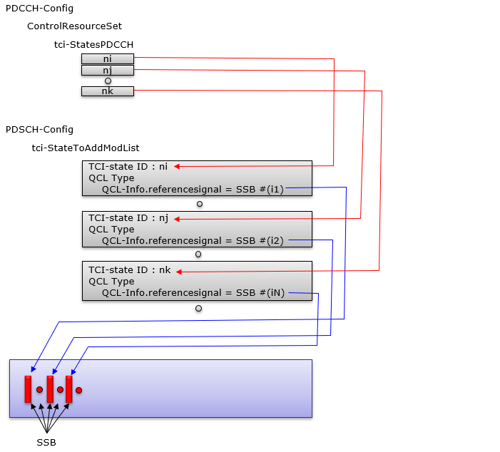
Following is the bulletized description of the illustration
-
The PDCCH beam is defined through TCI-states listed in the tci-StatesPDCCH field of the ControlResourceSet.
-
Each TCI-state used by PDCCH must correspond to a TCI-state defined in tci-StateToAddModList under PDSCH-Config.
-
Every TCI-state in PDSCH-Config contains QCL-Info pointing to a specific SSB index.
-
This means each PDCCH TCI-state inherits its spatial and timing relation from the SSB that the corresponding PDSCH TCI-state references.
-
The TCI-state IDs for PDCCH (e.g., ni, nj, nk) act as links to the matching TCI-states in PDSCH-Config.
-
Those matching TCI-states define the QCL type and the SSB used as the reference signal.
-
Because SSBs are the first signals the UE detects, the UE already knows their beam directions and timing.
-
By tying PDCCH to SSB-based QCL, the UE can decode PDCCH using the same beam direction it learned from SSB measurements.
-
This alignment ensures that the control channel beam is consistent with the broadcast synchronization beams.
-
As a result, PDCCH decoding becomes more reliable because the UE does not need a separate reference for beam direction; it simply reuses the known SSB beam structure through QCL.
Example 2 > PDCCH QCLed with CSI-RS
In this example, the PDCCH beam is tied not to SSBs but to specific NZP-CSI-RS resources, and the mapping is performed through TCI states defined in PDSCH-Config. Each TCI-state used by the PDCCH points to a TCI-state in the tci-StateToAddModList, and that TCI-state contains QCL-Info referencing a CSI-RS resource ID. The CSI-RS resources themselves are defined in nzp-CSI-RS-ResourceAddModList under MeasureConfig, so the UE has already measured these CSI-RS beams. As a result, the PDCCH beam is considered quasi-co-located with the selected CSI-RS resource, allowing the UE to decode PDCCH using the spatial and timing properties associated with that CSI-RS. This creates a clean linkage: PDCCH → TCI-state → QCL-Info → CSI-RS, ensuring that control-channel beamforming follows the same structure the UE has already learned from CSI measurements.
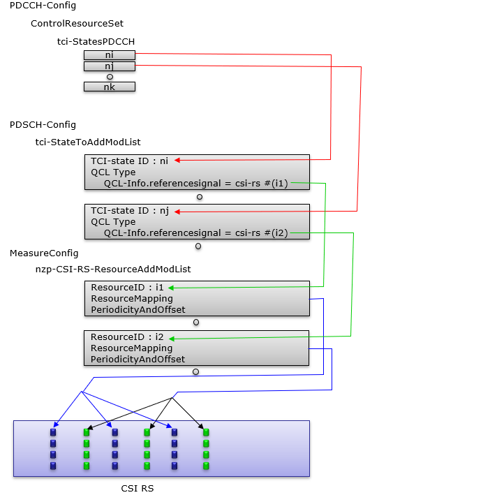
Following is the bulletized description of the illustration
-
In this example, PDCCH does not rely on SSB for QCL; it uses CSI-RS instead.
-
The PDCCH TCI-state list (tci-StatesPDCCH) contains TCI-state IDs such as ni and nj.
-
Each of these TCI-state IDs must correspond to a TCI-state inside tci-StateToAddModList under PDSCH-Config.
-
In PDSCH-Config, each TCI-state includes QCL-Info with referenceSignal = csi-rs #(i1) or csi-rs #(i2).
-
These csi-rs indices refer to NZP-CSI-RS resources defined in nzp-CSI-RS-ResourceAddModList within MeasureConfig.
-
Because the UE already measures these CSI-RS resources, it knows their beam direction, timing, and frequency characteristics.
-
The PDCCH inherits these characteristics through QCL-Type information included in each TCI-state.
-
This creates a chain: PDCCH → TCI-state → QCL-Info → CSI-RS resource.
-
As a result, PDCCH decoding becomes aligned with the CSI-RS beams instead of SSB beams.
-
This mechanism is especially useful when the network wants control-channel beamforming to follow the same CSI-RS structure used for downlink data and CSI acquisition.
Example 3 > PDCCH QCLed with SSB and CSI-RS
In this example, the PDCCH beam is allowed to reference both SSB-based and CSI-RS-based QCL sources, giving the network greater flexibility in how it aligns the control-channel beam with the UE’s measurement framework. Each PDCCH TCI-state maps to a corresponding entry in the PDSCH TCI-StateToAddModList, but those entries do not all point to the same type of reference signal. One TCI-state may use an SSB as its QCL reference while another uses an NZP-CSI-RS resource defined in the measurement configuration. Because the UE already measures both SSBs and CSI-RS resources, it can apply the correct timing and spatial parameters based on whichever reference is selected. As a result, PDCCH can switch between SSB-anchored beams and CSI-RS-anchored beams depending on coverage, mobility, or beam-management strategy, while still maintaining consistent QCL behavior for decoding.
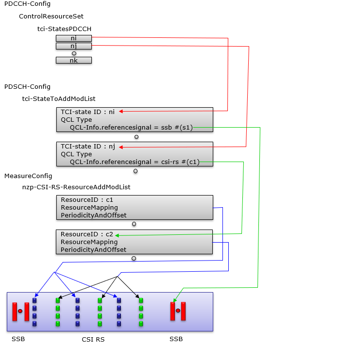
Following is the bulletized description of the illustration
PDCCH-config provides multiple TCI-state candidates - The ControlResourceSet contains several TCI-state IDs (ni, nj, nk).
- These TCI-states represent possible spatial/temporal configurations that PDCCH may use.
- The UE selects among these states based on MAC-CE activation or higher-layer signaling.
Each PDCCH TCI-state maps to a PDSCH tci-StateToAddModList entry - TCI-state ni maps to a PDSCH TCI entry referencing an SSB (e.g., s1).
- TCI-state nj maps to a PDSCH TCI entry referencing a CSI-RS resource (e.g., c1).
- This mapping ensures control and data beams inherit consistent QCL characteristics.
QCL-Type defines which properties are inherited - SSB-based QCL provides timing-related properties: Doppler shift, delay spread, and potentially spatial Rx if TypeD is included.
- CSI-RS-based QCL inherits parameters from NZP-CSI-RS resources configured for measurement or TRS.
- This allows the UE to maintain coherent demodulation regardless of the reference signal used.
MeasureConfig defines available CSI-RS resources - NZP-CSI-RS-ResourceAddModList includes CSI-RS resources such as c1 and c2.
- Each resource defines PeriodicityAndOffset and ResourceMapping.
- These CSI-RS resources are eligible QCL anchors for PDSCH TCI-states.
SSB and CSI-RS coexist as QCL anchors - SSBs are transmitted periodically and CSI-RS resources in between SSBs
- This illustrates that beams may originate from multiple reference signal families.
- The UE switches between them depending on which TCI-state is active for PDCCH.
Overall effect: flexible PDCCH beam alignment - Network can use SSB-based alignment for coverage or synchronization.
- Network can switch to CSI-RS-based alignment for precise beam tracking and mobility.
- The UE inherits correct timing and spatial behavior from the selected reference, ensuring stable demodulation performance.
Example 4 > CSI-RS beam QCLed with SSB beam
In this example, the network aligns a large set of narrow CSI-RS beams with a smaller set of wide SSB beams, creating a structured beam-pairing relationship through TCI and QCL signaling. Each CSI-RS resource in the measurement configuration is assigned a periodicity index that ties it to a specific SSB, and the TCI-StatesToAddModList reflects this mapping by giving each CSI-RS resource a corresponding TCI-state whose referenceSignal points back to the associated SSB. As a result, even though the network transmits many finely focused CSI-RS beams for accurate beam refinement, the UE can still interpret them using the broader SSB beams as spatial anchors. This allows the UE to move smoothly from wide-beam discovery (SSB) to narrow-beam tracking (CSI-RS), while maintaining consistent QCL behavior in timing and spatial domains.
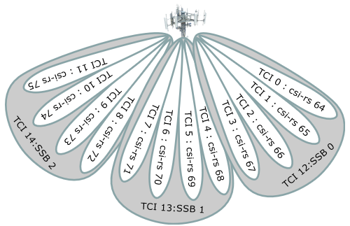
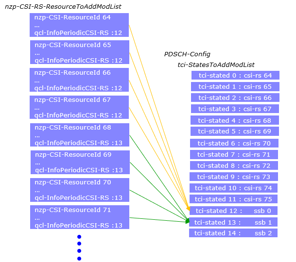
Following is an example showing the colocating a narrow beam(beam 64) with a widebeam(ssb 0). Follow the color coding for the connection as shown above.
nzp-CSI-RS-ResourceToAddModList
{
nzp-CSI-RS-ResourceId
reourceMapping
{
frequencyDomainAllocation row1 = '0010'
nrofPorts = p1,
firstOFDMSymbolInTimeDomain = 4,
cdm-Type = noCDM,
density = three,
freqBand
{
startingRB = 0,
nrofRBs = 68
}
},
powerControlOffset = 0,
powerControlOffsetSS = db0,
scramblingID = 0,
periodicityAndOffset = slots160:40,
qcl-InfoPeriodicCSI-RS =
}
}
tci-StatesToAddModList
{
....
{
tci-StateId = 12,
qcl-Type1
{
bwp-Id = 0,
referenceSignal ssb :
qcl-Type = TypeC
}
qcl-Type2
{
bwp-Id = 0,
referenceSignal ssb :
qcl-Type = TypeD
}
}
.....
}
ssb-PositionInBurst longBitmap =
Following is the bulletized description of the illustration
The network defines many CSI-RS beams but only a few SSB beams. - CSI-RS beams are narrow and high-resolution, while SSB beams are wide.
- SSBs act as spatial anchors and CSI-RS beams provide fine-grained beam refinement.
Each CSI-RS resource in nzp-CSI-RS-ResourceToAddModList is linked to an SSB via QCL. - The field
qcl-InfoPeriodicCSI-RS = Xmaps a CSI-RS resource to a specific SSB index. - This creates a fixed relation: a CSI-RS beam behaves as if it shares physical properties with its mapped SSB.
- The field
PDSCH configuration maps each CSI-RS resource to a TCI-state. tci-StatesToAddModListcontains TCI entries (tci-stateId 0, 1, 2, ...).- Each TCI entry references the same SSB that its corresponding CSI-RS is QCLed with.
Each TCI-state defines both QCL-TypeC and QCL-TypeD. - TypeC lets the UE inherit timing-related parameters such as delay, average delay, and Doppler.
- TypeD lets the UE inherit spatial receive parameters, i.e., the beam direction.
- This enables the UE to reuse SSB-based estimation when receiving CSI-RS-based PDSCH.
The end result is a “beam hierarchy.” - A narrow CSI-RS beam (e.g., beam 64) is logically tied to a wide SSB (e.g., SSB 0).
- The UE treats the CSI-RS beam as a refined version of the SSB beam.
- The UE tracks mobility with broad SSB beams and decodes data with narrow CSI-RS beams.
The illustrated RRC example shows the explicit connection. - CSI-RS
resourceId 64includesqcl-InfoPeriodicCSI-RS = 12. - TCI-stateId 12 references
referenceSignal ssb : 0. - This confirms that CSI-RS beam 64 is quasi-co-located with SSB 0.
- CSI-RS
This configuration supports advanced beamforming with low signaling overhead. - The UE does not need to treat every narrow CSI-RS beam as a completely independent reference.
- It uses SSB as the baseline and refines beam direction with CSI-RS, guided by QCL relations in TCI-states.
RRC Messages on QCI
TCI configuration in NR is built across several RRC structures, each defining a different part of the beam-selection and QCL signaling chain. ControlResourceSet configures how PDCCH is transmitted, including the list of TCI states that the UE may use when receiving control channels. PDSCH-Config extends this concept by defining a larger pool of TCI states, each carrying QCL information that links the downlink data channel to a specific reference signal such as an SSB or CSI-RS resource. The TCI-State and QCL-Info structures provide the fundamental mapping between the target channel and its QCL source, specifying timing, frequency, or spatial equivalence through typeA, typeB, typeC, or typeD relations. NZP-CSI-RS-ResourceSet and CSI-MeasConfig define how CSI-RS resources are grouped, repeated, and tied to the UE’s measurement configuration, including the ability to associate each periodic CSI-RS with a TCI-State. These RRC elements work together to form a hierarchical signaling mechanism that allows the gNB to control beam association for PDCCH, PDSCH, and CSI-RS with minimal overhead while ensuring that the UE always knows which spatial filter and timing estimation to apply for each transmission opportunity.
ControlResourceSet defines TCI usage for PDCCH reception. - Specifies which TCI-StateIds are valid for control channel decoding.
- Defines mapping structure, REG bundling, and precoder granularity that interact with beam selection.
- Provides the first layer of TCI constraints that the UE must apply for PDCCH monitoring.
PDSCH-Config provides the main pool of TCI states for data channels. - tci-StatesToAddModList defines up to 128 TCI-State entries containing QCL relationships.
- Each TCI-State can include one or two QCL-Info blocks (qcl-Type1, qcl-Type2).
- Defines how PDSCH inherits timing, Doppler, or spatial parameters from SSB or CSI-RS.
- Serves as the primary source for DCI-based TCI selection when tci-PresentInDCI is enabled.
TCI-State and QCL-Info define the actual QCL relationship. - TCI-State specifies the stateId and associated qcl-Type1 and qcl-Type2 relations.
- QCL-Info identifies the QCL source: SSB or NZP-CSI-RS.
- qcl-Type (A/B/C/D) determines what properties the UE inherits:
- typeA → timing and Doppler alignment
- typeB → frequency-related parameters
- typeC → average delay & Doppler spread
- typeD → spatial receive filter (beam direction)
NZP-CSI-RS-ResourceSet defines CSI-RS groups and TRS behavior. - Groups multiple CSI-RS resources under one resource set.
- trs-Info indicates whether all CSI-RS ports share the same antenna configuration.
- Repetition and triggering parameters influence QCL applicability and reference-signal consistency.
CSI-MeasConfig links measurement CSI-RS resources into the configuration chain. - Defines the NZP-CSI-RS-ResourceToAddModList for measurement-related CSI-RS.
- Periodic CSI-RS resources may include qcl-InfoPeriodicCSI-RS for mapping to a TCI-State.
- Allows the UE to treat periodic CSI-RS beams as QCL sources for PDSCH or other channels.
NZP-CSI-RS-Resource describes the detailed structure of each CSI-RS resource. - Contains resourceMapping, power offsets, scrambling ID, periodicity, and QCL information.
- qcl-InfoPeriodicCSI-RS points to a TCI-State controlling how the UE interprets the CSI-RS beam.
- Enables hierarchical QCL linking: CSI-RS → TCI-State → PDSCH/PDCCH beam selection.
Overall, these RRC structures form a hierarchical TCI/QCL framework. - ControlResourceSet manages PDCCH beam selection.
- PDSCH-Config provides the master list of TCI states for data channels.
- TCI-State and QCL-Info define the physical equivalence between channels and reference signals.
- CSI-RS resource sets and resources provide measurement beams and QCL anchors.
- The UE resolves beam direction, timing, and Doppler using these layers with minimal overhead.
ControlResourceSet ::= SEQUENCE {
controlResourceSetId ControlResourceSetId,
frequencyDomainResources BIT STRING (SIZE (45)),
duration INTEGER (1..maxCoReSetDuration),
//maxCoReSetDuration = 3
cce-REG-MappingType CHOICE {
interleaved SEQUENCE {
reg-BundleSize ENUMERATED {n2, n3, n6},
interleaverSize ENUMERATED {n2, n3, n6},
shiftIndex INTEGER(0..maxNrofPhysicalResourceBlocks-1)
},
nonInterleaved NULL
},,
precoderGranularity ENUMERATED {sameAsREG-bundle, allContiguousRBs},
pdcch-DMRS-ScramblingID BIT STRING (SIZE (16)) OPTIONAL
}
PDSCH-Config ::= SEQUENCE {
dataScramblingIdentityPDSCH INTEGER (0..1007) OPTIONAL,
dmrs-DownlinkForPDSCH-MappingTypeA SetupRelease { DMRS-DownlinkConfig } OPTIONAL,
dmrs-DownlinkForPDSCH-MappingTypeB SetupRelease { DMRS-DownlinkConfig } OPTIONAL,
tci-StatesToAddModList SEQUENCE (SIZE(1..maxNrofTCI-States))
OF TCI-State OPTIONAL, -- Need N
tci-StatesToReleaseList SEQUENCE (SIZE(1..maxNrofTCI-States))
OF TCI-StateId OPTIONAL, -- Need N
vrb-ToPRB-Interleaver ENUMERATED {n2, n4},
resourceAllocation ENUMERATED { resourceAllocationType0,
resourceAllocationType1,
dynamicSwitch},
pdsch-AllocationList SEQUENCE (SIZE(1..maxNrofDL-Allocations))
OF PDSCH-TimeDomainResourceAllocation ,
pdsch-AggregationFactor ENUMERATED { n2, n4, n8 } OPTIONAL,
rateMatchPatternToAddModList SEQUENCE (SIZE (1..maxNrofRateMatchPatterns))
OF RateMatchPattern OPTIONAL, -- Need N
rateMatchPatternToReleaseList SEQUENCE (SIZE (1..maxNrofRateMatchPatterns))
OF RateMatchPatternId OPTIONAL, -- Need N
rateMatchPatternGroup1 SEQUENCE (SIZE (1..maxNrofRateMatchPatterns))
OF RateMatchPatternId OPTIONAL, -- Need R
rateMatchPatternGroup2 SEQUENCE (SIZE (1..maxNrofRateMatchPatterns))
OF RateMatchPatternId OPTIONAL, -- Need R
rbg-Size ENUMERATED {config1, config2},
mcs-Table ENUMERATED {qam64, qam256},
maxNrofCodeWordsScheduledByDCI ENUMERATED {n1, n2} OPTIONAL, -- Need R
prb-BundlingType CHOICE {
static SEQUENCE {
bundleSize ENUMERATED { n4, wideband } OPTIONAL
},
dynamic SEQUENCE {
bundleSizeSet1 ENUMERATED { n4,
wideband,
n2-wideband,
n4-wideband
} OPTIONAL, -- Need S
bundleSizeSet2 ENUMERATED { n4,
wideband
} OPTIONAL -- Need S
}
},
zp-CSI-RS-ResourceToAddModList SEQUENCE (SIZE (1..maxNrofZP-CSI-RS-Resources))
OF ZP-CSI-RS-Resource OPTIONAL, -- Need N
zp-CSI-RS-ResourceToReleaseList SEQUENCE (SIZE (1..maxNrofZP-CSI-RS-Resources))
OF ZP-CSI-RS-ResourceId OPTIONAL, -- Need M
aperiodic-ZP-CSI-RS-ResourceSetsToAddModList SEQUENCE (SIZE (1..maxNrofZP-CSI-RS-Sets))
OF ZP-CSI-RS-ResourceSet OPTIONAL, -- Need N
aperiodic-ZP-CSI-RS-ResourceSetsToReleaseList SEQUENCE (SIZE (1..maxNrofZP-CSI-RS-Sets))
OF ZP-CSI-RS-ResourceSetId OPTIONAL, -- Need N
sp-ZP-CSI-RS-ResourceSetsToAddModList SEQUENCE (SIZE (1..maxNrofZP-CSI-RS-Sets))
OF ZP-CSI-RS-ResourceSet OPTIONAL, -- Need N
sp-ZP-CSI-RS-ResourceSetsToReleaseList SEQUENCE (SIZE (1..maxNrofZP-CSI-RS-Sets))
OF ZP-CSI-RS-ResourceSetId OPTIONAL, -- Need N
...
}
TCI-State ::= SEQUENCE {
tci-StateId TCI-StateId,
...
}
QCL-Info ::= SEQUENCE {
cell ServCellIndex OPTIONAL, -- Need R
bwp-Id BWPId OPTIONAL, -- Cond CSI-RS-Indicated
...
}
NZP-CSI-RS-ResourceSet ::= SEQUENCE {
nzp-CSI-ResourceSetId NZP-CSI-RS-ResourceSetId,
nzp-CSI-RS-Resources SEQUENCE (SIZE (1..maxNrofNZP-CSI-RS-ResourcesPerSet))
OF NZP-CSI-RS-ResourceId,
aperiodicTriggeringOffset INTEGER(0..4) OPTIONAL, -- Need S
...
}
CSI-MeasConfig ::= SEQUENCE {
nzp-CSI-RS-ResourceToAddModList SEQUENCE (SIZE (1..maxNrofNZP-CSI-RS-Resources))
OF NZP-CSI-RS-Resource OPTIONAL,
..
}
NZP-CSI-RS-Resource ::= SEQUENCE {
nzp-CSI-RS-ResourceId NZP-CSI-RS-ResourceId,
resourceMapping CSI-RS-ResourceMapping,
powerControlOffset INTEGER (-8..15),
powerControlOffsetSS ENUMERATED{db-3, db0, db3, db6} OPTIONAL, -- Need R
scramblingID ScramblingId,
periodicityAndOffset CSI-ResourcePeriodicityAndOffset OPTIONAL,-
qcl-InfoPeriodicCSI-RS TCI-StateId OPTIONAL, -- Cond Periodic
...
}
CSI-RS-ResourceMapping ::= SEQUENCE {
frequencyDomainAllocation CHOICE {
row1 BIT STRING (SIZE (4)),
row2 BIT STRING (SIZE (12)),
row4 BIT STRING (SIZE (3)),
other BIT STRING (SIZE (6))
},
nrofPorts ENUMERATED {p1,p2,p4,p8,p12,p16,p24,p32},
firstOFDMSymbolInTimeDomain INTEGER (0..13),
firstOFDMSymbolInTimeDomain2 INTEGER (2..12) OPTIONAL, -- Need R
cdm-Type ENUMERATED {noCDM, fd-CDM2, cdm4-FD2-TD2, cdm8-FD2-TD4},
density CHOICE {
dot5 ENUMERATED {evenPRBs, oddPRBs},
one NULL,
three NULL,
spare NULL
},
freqBand CSI-FrequencyOccupation,
...
}
CSI-ResourcePeriodicityAndOffset ::= CHOICE {
slots4 INTEGER (0..3),
slots5 INTEGER (0..4),
slots8 INTEGER (0..7),
slots10 INTEGER (0..9),
slots16 INTEGER (0..15),
slots20 INTEGER (0..19),
slots32 INTEGER (0..31),
slots40 INTEGER (0..39),
slots64 INTEGER (0..63),
slots80 INTEGER (0..79),
slots160 INTEGER (0..159),
slots320 INTEGER (0..319),
slots640 INTEGER (0..639)
}
Reference
- 3GPP TSG-RAN WG1 #87ah-NR - R1-1700771 : On spatial QCL definition
- QuasiCo-locationType-Drelation betweenhierarchicalbeamsina GridofBeamssetup. - Mohamad MESTOUKIRDI (Thesis paper)