According to R1-1700771, QCL is defined as follows :
Two antenna ports are said to be quasi co-located if properties of the channel over which a symbol on one antenna port is conveyed can be inferred from the channel over which a symbol on the other antenna port is conveyed
Don't get disappointed if this does not sound clear to you. It is same to me as well. I may not understand the detailed physics and mathematics behind this forever, but I think I need to know at least some high level parameters about this.
It will take long time to get real / practical meaning of this statement. If you are familiar with the definition of Antenna port in LTE, you would noticed that the definition shown here is very similar to Antenna Port in LTE except a couple of words.
Simply put you may think that Antenna port defines the correlation between symbols within a same antenna port and QCL defines the correlation between symbols from different antenna ports.
- QCL Types
- What does it really mean ?
- Triggering TCI
- Mapping between QCL-Type configurations and TCI-RS-Set / DMRS
- How UE figure out TCI-State for PDCCH for each specific moment ?
- How UE figure out TCI-State for downlink data PDSCH for each specific moment ?
- Case 1 : When tci-PresentInDCI = omit or PDSCH is scheduled by DCI 1_0.
- Case 2 : When tci-PresentInDCI = enabled.
- Examples of TCI configuration in RRC
- Example 1 > PDCCH QCLed with SSB
- Example 2 > PDCCH QCLed with CSI-RS
- Example 3 > PDCCH QCLed with SSB and CSI-RS
- Example 4 > CSI-RS beam QCLed with SSB beam
QCL Types
"38.214 - 5.1.5 Antenna ports quasi co-location" defines four difference types of QCL as listed below.
|
QCL Type |
Description |
|
QCL-TypeA |
Doppler shift, Doppler spread, average delay, delay spread |
|
QCL-TypeB |
Doppler shift, Doppler spread' |
|
QCL-TypeC |
Average delay, Doppler shift |
|
QCL-TypeD |
Spatial Rx parameter |
What does it really mean ?
I wrote about the formal definition of QCL and the types of QCL. What does it really mean ? When somebody says 'A signal (A) is QCLed (Quasi Colacated) with another signal (B)', do you really understand what this mean ?
I would say in my own words as follows.
i) The two signal (A) and (B) has gone through very similar channel condition.
ii) In order for (A) and (B) to go through the similar channel, it is highly likely that they are from the same location(i.e, same place and same antenna). ==> More specifically, it implies that the signal (A) and (B) are transmitted from the same TRP(Antenna Array) that applies the same Spatial Filter.
iii) Since the two signal reaches the reciever through similar channel, if the reciever can detect one of the signal (e.g, Signal A) and figure out the channel properties of the signal, it will greatly help to detect the other signal (e.g, Signal B).
Let me give you more concrete example using NR terminology. What would it mean if I say 'the PDCCH from a gNB is QCLed with SSB'. What would this mean ?
I would mean that the PDCCH went through the similar channel condition as SSB. The channel information estimated to detect SSB can help detect PDCCH as well.
Now let's get into just a little bit deeper. When you say 'channel condition', what does it exactly mean ? There can be a lot of factors that defines the channel condition, but current 3GPP defines several parameters to define the channel condition as listed below.
- Doppler Shift
- Doppler Spread
- Average Delay
- Delay Spread
- Spatial Rx Parameter
One or more of these factors would form a property of the channel that two signal shares and the predefined group of these factors are labeled as QCL type that is mentioned in previous section.
Putting all these togother, we can define the relationship of two related signal like ... 'The PDCCH signal from the gNB is QCLed with SSB via Type C'. This mean that the PDCCH and the SSB went through the similar radio channel sharing the similar properties in terms of Average Delay and Doppler Shift.
Triggering TCI
I wrote this table based on the descriptions in "38.214 - 5.1.5 Antenna ports quasi co-location"
|
Steps |
Direction |
Description |
|
1 |
UE <-- NW |
RRC Configures TCI related parameters |
|
2 |
UE <-- NW |
NW Send MAC CE Activation Commnd |
|
3 |
UE |
UE recieves the PDSCH carrying the MAC CE |
|
4 |
UE --> NW |
UE sends HARQ ACK at slot n |
|
5 |
UE/NW |
TCI configured in Transmission Configuration Indication of DCI 1_1 is applied from the slot (n + 3 subrames + 1). |
Mapping between QCL-Type configurations and TCI-RS-Set / DMRS
Which QCL-Type is applied is determined by TCI-RS-Set and DMRS. "38.214 - 5.1.5 Antenna ports quasi co-location" states about the mapping between QCL-Type and TCI-RS-Set as follows. The statement in this specification is not so clear (actually confusing) to me. I am not 100% confident on whether I interpreted correctly or not. Feel free to let me know if you have any different interpretation.
< QCL for CSI Resource >
|
TCI-RS-Set Configuration |
QCL Type that TCI-State indicates |
|
|
QCL Type |
QCLed Reference Signal |
|
|
CSI Resource Type = periodic NZP-CSI-RS-ResourceSet.trs-Info = true NZP-CSI-RS-ResourceSet.repetition = off |
QCL-TypeC and ,if applicable, TypeD
Ex 1> { tci-StateId n, qcl-Type1 { bwp-Id b, } }
Ex 2> { tci-StateId n, qcl-Type1 { bwp-Id b, } qcl-Type2 { bwp-Id b, } }
|
SS/PBCH Block |
|
CSI Resource Type = periodic NZP-CSI-RS-ResourceSet.trs-Info = true NZP-CSI-RS-ResourceSet.repetition = on |
QCL-TypeC and ,if applicable, QCL-TypeD
Ex 1> { tci-StateId n, qcl-Type1 { bwp-Id b, } }
Ex 2> { tci-StateId n, qcl-Type1 { bwp-Id b, } qcl-Type2 { bwp-Id b, } } |
SS/PBCH Block
NZP-CSI-RS-ResourceSet |
|
CSI Resource Type = aperiodic NZP-CSI-RS-ResourceSet.trs-Info = true |
QCL-TypeA and ,if applicable, TypeD
Ex 1> { tci-StateId n, qcl-Type1 { bwp-Id b, } }
Ex 1> { tci-StateId n, qcl-Type1 { bwp-Id b, } qcl-Type2 { bwp-Id b, } } |
a periodic CSI-RS resource in a NZP-CSI-RS-ResourceSet |
|
NZP-CSI-RS-ResourceSet.trs-Info not confgured NZP-CSI-RS-ResourceSet.repetition not configured |
QCL-TypeA and ,if applicable, TypeD
Ex 1> { tci-StateId n, qcl-Type1 { bwp-Id b, } }
Ex 2> { tci-StateId n, qcl-Type1 { bwp-Id b, } qcl-Type2 { bwp-Id b, } } |
CSI-RS resource in a NZP-CSI-RS-ResourceSet |
|
QCL-TypeA and ,if applicable, TypeD
Ex 1 > { tci-StateId n, qcl-Type1 { bwp-Id b, } }
Ex 2 > { tci-StateId n, qcl-Type1 { bwp-Id b, } qcl-Type2 { bwp-Id b, } } |
CSI-RS resource in a NZP-CSI-RS-ResourceSet
SS/PBCH block |
|
|
QCL-TypeA and ,if applicable, TypeD
Ex 1> { tci-StateId n, qcl-Type1 { bwp-Id b, } }
Ex 2> { tci-StateId n, qcl-Type1 { bwp-Id b, } qcl-Type2 { bwp-Id b, } } |
CSI-RS resource in a NZP-CSI-RS-ResourceSet |
|
|
QCL-TypeB and TypeD not applicable
Ex > { tci-StateId n, qcl-Type1 { bwp-Id b, } } |
CSI-RS resource in a NZP-CSI-RS-ResourceSet |
|
|
NZP-CSI-RS-ResourceSet.repetition = on |
QCL-TypeA and ,if applicable, TypeD
Ex 1> { tci-StateId n, qcl-Type1 { bwp-Id b, } }
Ex 2> { tci-StateId n, qcl-Type1 { bwp-Id b, } qcl-Type2 { bwp-Id b, } } |
CSI-RS resource in a NZP-CSI-RS-ResourceSet configured with higher layer parameter trs- Info |
|
QCL-TypeA and ,if applicable, TypeD
Ex 1> { tci-StateId n, qcl-Type1 { bwp-Id b, } }
Ex 2> { tci-StateId n, qcl-Type1 { bwp-Id b, } qcl-Type2 { bwp-Id b, } } |
CSI-RS resource in a NZP-CSI-RS-ResourceSet configured with higher layer parameter trs-Info |
|
|
QCL-TypeC and ,if applicable, TypeD
Ex 1 > { tci-StateId n, qcl-Type1 { bwp-Id b, } }
Ex 2 > { tci-StateId n, qcl-Type1 { bwp-Id b, } qcl-Type2 { bwp-Id b, } } |
SS/PBCH block |
|
< QCL for CSI DMRS >
|
DMRS Type |
QCL Type that TCI-State indicates |
|
PDCCH DMRS |
|
|
PDSCH DMRS |
|
How UE figure out TCI-State for PDCCH for each specific moment ?
The overall process of applying TCI for this case is as follows.
Step 1 : A TCI State table called 'tci-StatesToAddModList' is defined in PDSCH-Config. The max size of the table is 128.
Step 2 : Select a subset of the tables from tci-StatesToAddModList and put them into ControlResourceSet.tci-StatesPDCCH-ToAddList. The max size of this table is 64.
Step 3 : Apply a specific tci-States defined in Step 2 via TCI State Indication for UE-specific PDCCH MAC CE.
How UE figure out TCI-State for downlink data PDSCH for each specific moment ?
There are roughly two cases we can think of configuring TCI-State on UE side. This process is described in very complicated way (at least to me) in 38.214 and it was hard for me to get some big picture. Followings are what I interpret the specification.
In this case, UE used TCI state for CORESET/PDCCH as the TCI state for PDSCH. it means
TCI state for PDSCH = TCI state for CORESET/PDCCH
In this case, UE used TCI specified in DCI 1_1. Sound simple ? It may look simple, but the problem is that TCI field in DCI 1_1 is just a number ranging 0 through 7. It does not have any details in it. This is where the complication /confusion comes in. Following is what I understand (but some possibility of errors. please let me know if you don't agree with my understanding). It goes in a few steps as follows.
Step 1 : A TCI State table called 'tci-StatesToAddModList' is defined in PDSCH-Config. The max size of the table is 128.
Step 2 : Select a subset of the tables from tci-StatesToAddModList and put them into a smaller table 'codepoint'. This is done by the 'TCI States Activation/Deactivation for UE-specific PDSCH MAC CE'. The max size of this table is 8.
Step 3 : For each PDSCH scheduling, the TCI field(Transmission Configuration Indication) field in DCI 1_1 indicate a specific index of the table defined in Step 2.
Examples of TCI configuration in RRC
One of the reality behind QCL is that it is extremly difficult to grasp the real meaning of it, but even harder reality is that it is even more difficult to configure those things in signaling message. I hope a few example illustration shown here would help you to get some big picture of the configuration.
TCI index in PDSCH is associated with csi-MeasureConfig as below.
PDSCH-Config.
--> CSI-MeasConfig.
Example 1 > PDCCH QCLed with SSB
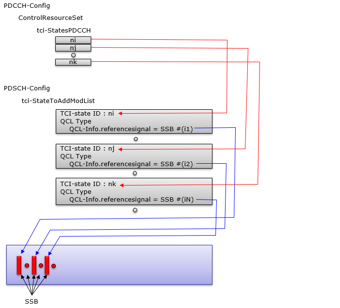
Example 2 > PDCCH QCLed with CSI-RS
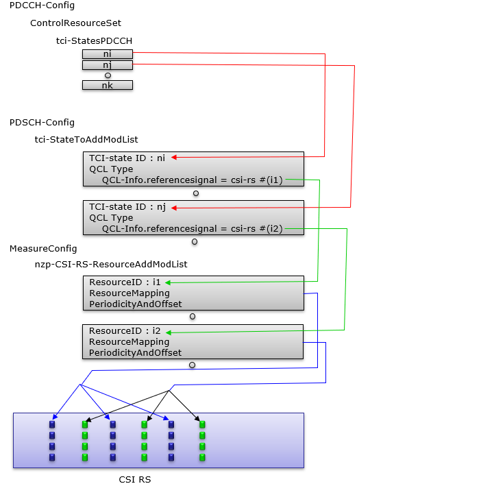
Example 3 > PDCCH QCLed with SSB and CSI-RS
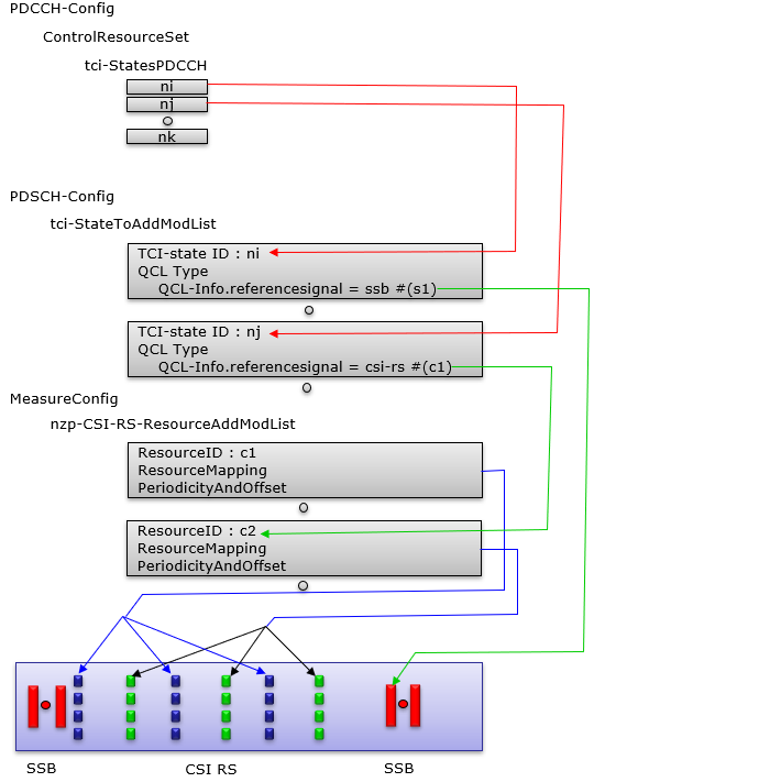
Example 4 > CSI-RS beam QCLed with SSB beam
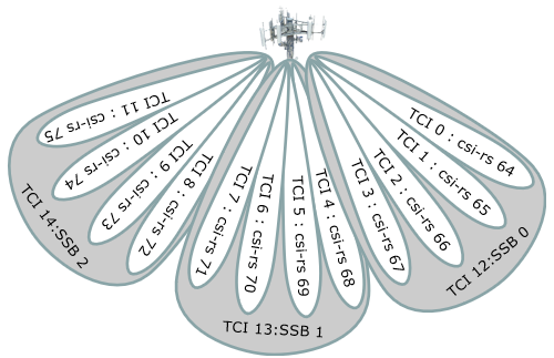
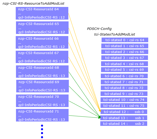
Following is an example showing the colocating a narrow beam(beam 64) with a widebeam(ssb 0). Follow the color coding for the connection as shown above.
nzp-CSI-RS-ResourceToAddModList
{
nzp-CSI-RS-ResourceId
reourceMapping
{
frequencyDomainAllocation row1 = '0010'
nrofPorts = p1,
firstOFDMSymbolInTimeDomain = 4,
cdm-Type = noCDM,
density = three,
freqBand
{
startingRB = 0,
nrofRBs = 68
}
},
powerControlOffset = 0,
powerControlOffsetSS = db0,
scramblingID = 0,
periodicityAndOffset = slots160:40,
qcl-InfoPeriodicCSI-RS =
}
}
tci-StatesToAddModList
{
....
{
tci-StateId = 12,
qcl-Type1
{
bwp-Id = 0,
referenceSignal ssb :
qcl-Type = TypeC
}
qcl-Type2
{
bwp-Id = 0,
referenceSignal ssb :
qcl-Type = TypeD
}
}
.....
}
ssb-PositionInBurst longBitmap =
RRC Messages on QCI
ControlResourceSet ::= SEQUENCE {
controlResourceSetId ControlResourceSetId,
frequencyDomainResources BIT STRING (SIZE (45)),
duration INTEGER (1..maxCoReSetDuration),
//maxCoReSetDuration = 3
cce-REG-MappingType CHOICE {
interleaved SEQUENCE {
reg-BundleSize ENUMERATED {n2, n3, n6},
interleaverSize ENUMERATED {n2, n3, n6},
shiftIndex INTEGER(0..maxNrofPhysicalResourceBlocks-1)
},
nonInterleaved NULL
},,
precoderGranularity ENUMERATED {sameAsREG-bundle, allContiguousRBs},
pdcch-DMRS-ScramblingID BIT STRING (SIZE (16)) OPTIONAL
}
PDSCH-Config ::= SEQUENCE {
dataScramblingIdentityPDSCH INTEGER (0..1007) OPTIONAL,
dmrs-DownlinkForPDSCH-MappingTypeA SetupRelease { DMRS-DownlinkConfig } OPTIONAL,
dmrs-DownlinkForPDSCH-MappingTypeB SetupRelease { DMRS-DownlinkConfig } OPTIONAL,
tci-StatesToAddModList SEQUENCE (SIZE(1..maxNrofTCI-States))
OF TCI-State OPTIONAL, -- Need N
tci-StatesToReleaseList SEQUENCE (SIZE(1..maxNrofTCI-States))
OF TCI-StateId OPTIONAL, -- Need N
vrb-ToPRB-Interleaver ENUMERATED {n2, n4},
resourceAllocation ENUMERATED { resourceAllocationType0,
resourceAllocationType1,
dynamicSwitch},
pdsch-AllocationList SEQUENCE (SIZE(1..maxNrofDL-Allocations))
OF PDSCH-TimeDomainResourceAllocation ,
pdsch-AggregationFactor ENUMERATED { n2, n4, n8 } OPTIONAL,
rateMatchPatternToAddModList SEQUENCE (SIZE (1..maxNrofRateMatchPatterns))
OF RateMatchPattern OPTIONAL, -- Need N
rateMatchPatternToReleaseList SEQUENCE (SIZE (1..maxNrofRateMatchPatterns))
OF RateMatchPatternId OPTIONAL, -- Need N
rateMatchPatternGroup1 SEQUENCE (SIZE (1..maxNrofRateMatchPatterns))
OF RateMatchPatternId OPTIONAL, -- Need R
rateMatchPatternGroup2 SEQUENCE (SIZE (1..maxNrofRateMatchPatterns))
OF RateMatchPatternId OPTIONAL, -- Need R
rbg-Size ENUMERATED {config1, config2},
mcs-Table ENUMERATED {qam64, qam256},
maxNrofCodeWordsScheduledByDCI ENUMERATED {n1, n2} OPTIONAL, -- Need R
prb-BundlingType CHOICE {
static SEQUENCE {
bundleSize ENUMERATED { n4, wideband } OPTIONAL
},
dynamic SEQUENCE {
bundleSizeSet1 ENUMERATED { n4,
wideband,
n2-wideband,
n4-wideband
} OPTIONAL, -- Need S
bundleSizeSet2 ENUMERATED { n4,
wideband
} OPTIONAL -- Need S
}
},
zp-CSI-RS-ResourceToAddModList SEQUENCE (SIZE (1..maxNrofZP-CSI-RS-Resources))
OF ZP-CSI-RS-Resource OPTIONAL, -- Need N
zp-CSI-RS-ResourceToReleaseList SEQUENCE (SIZE (1..maxNrofZP-CSI-RS-Resources))
OF ZP-CSI-RS-ResourceId OPTIONAL, -- Need M
aperiodic-ZP-CSI-RS-ResourceSetsToAddModList SEQUENCE (SIZE (1..maxNrofZP-CSI-RS-Sets))
OF ZP-CSI-RS-ResourceSet OPTIONAL, -- Need N
aperiodic-ZP-CSI-RS-ResourceSetsToReleaseList SEQUENCE (SIZE (1..maxNrofZP-CSI-RS-Sets))
OF ZP-CSI-RS-ResourceSetId OPTIONAL, -- Need N
sp-ZP-CSI-RS-ResourceSetsToAddModList SEQUENCE (SIZE (1..maxNrofZP-CSI-RS-Sets))
OF ZP-CSI-RS-ResourceSet OPTIONAL, -- Need N
sp-ZP-CSI-RS-ResourceSetsToReleaseList SEQUENCE (SIZE (1..maxNrofZP-CSI-RS-Sets))
OF ZP-CSI-RS-ResourceSetId OPTIONAL, -- Need N
...
}
TCI-State ::= SEQUENCE {
tci-StateId TCI-StateId,
...
}
QCL-Info ::= SEQUENCE {
cell ServCellIndex OPTIONAL, -- Need R
bwp-Id BWPId OPTIONAL, -- Cond CSI-RS-Indicated
...
}
NZP-CSI-RS-ResourceSet ::= SEQUENCE {
nzp-CSI-ResourceSetId NZP-CSI-RS-ResourceSetId,
nzp-CSI-RS-Resources SEQUENCE (SIZE (1..maxNrofNZP-CSI-RS-ResourcesPerSet))
OF NZP-CSI-RS-ResourceId,
aperiodicTriggeringOffset INTEGER(0..4) OPTIONAL, -- Need S
...
}
CSI-MeasConfig ::= SEQUENCE {
nzp-CSI-RS-ResourceToAddModList SEQUENCE (SIZE (1..maxNrofNZP-CSI-RS-Resources))
OF NZP-CSI-RS-Resource OPTIONAL,
..
}
NZP-CSI-RS-Resource ::= SEQUENCE {
nzp-CSI-RS-ResourceId NZP-CSI-RS-ResourceId,
resourceMapping CSI-RS-ResourceMapping,
powerControlOffset INTEGER (-8..15),
powerControlOffsetSS ENUMERATED{db-3, db0, db3, db6} OPTIONAL, -- Need R
scramblingID ScramblingId,
periodicityAndOffset CSI-ResourcePeriodicityAndOffset OPTIONAL,-
qcl-InfoPeriodicCSI-RS TCI-StateId OPTIONAL, -- Cond Periodic
...
}
CSI-RS-ResourceMapping ::= SEQUENCE {
frequencyDomainAllocation CHOICE {
row1 BIT STRING (SIZE (4)),
row2 BIT STRING (SIZE (12)),
row4 BIT STRING (SIZE (3)),
other BIT STRING (SIZE (6))
},
nrofPorts ENUMERATED {p1,p2,p4,p8,p12,p16,p24,p32},
firstOFDMSymbolInTimeDomain INTEGER (0..13),
firstOFDMSymbolInTimeDomain2 INTEGER (2..12) OPTIONAL, -- Need R
cdm-Type ENUMERATED {noCDM, fd-CDM2, cdm4-FD2-TD2, cdm8-FD2-TD4},
density CHOICE {
dot5 ENUMERATED {evenPRBs, oddPRBs},
one NULL,
three NULL,
spare NULL
},
freqBand CSI-FrequencyOccupation,
...
}
CSI-ResourcePeriodicityAndOffset ::= CHOICE {
slots4 INTEGER (0..3),
slots5 INTEGER (0..4),
slots8 INTEGER (0..7),
slots10 INTEGER (0..9),
slots16 INTEGER (0..15),
slots20 INTEGER (0..19),
slots32 INTEGER (0..31),
slots40 INTEGER (0..39),
slots64 INTEGER (0..63),
slots80 INTEGER (0..79),
slots160 INTEGER (0..159),
slots320 INTEGER (0..319),
slots640 INTEGER (0..639)
}
Reference
- 3GPP TSG-RAN WG1 #87ah-NR - R1-1700771 : On spatial QCL definition
- QuasiCo-locationType-Drelation betweenhierarchicalbeamsina GridofBeamssetup. - Mohamad MESTOUKIRDI (Thesis paper)