Following is the list of the main characteristics of 802.11ac. Most of these main characteristics would lead to some addition / modification of PLCP and MAC frame structure. These detailed changes will be summarized in each corresponding sections. If you are not familiar with WLAN frame structure and basic operations I would recommend you to go through WLAN Frame structure and WLAN protocol page first.
- Motivation and Strategy
- Overall Specification / Requirement
- Detecting 802.11ac Access Point
- Detecting 802.11ac Station - Device
- VHT - Very High Throughput
- Dynamic Bandwidth Allocation
- Additional MAC Frame Types
- Beamforming Report Poll Frame
- VHT NDP Announcement
- VHT Compressed Beamforming Frame
- VHT preamble format for sounding PPDUs
- Channel measurement - sounding - procedures
- MU-MIMO BeamForming
- Compatibility
- Reference
Motivation and Strategy
As in almost every evolution of every communication technology (except IoT), the major motivation of 802.11ac is to achieve much higher throughput than the previous highest throughput technology (802.11n in this case). I am pretty sure that you will see another technology targeted for even higher throughput than 802.11ac (We are already hearing of 802.11ad).
Then what is the technical strategy to achieve this high throughput ? Overall strategy is also same as other technology (If you have seen the evolution process of celluar technology (e.g, WCDMA -> HSPA -> DC HSPA or LTE -> LTE MIMO -> Carrier Aggregation etc), you will easily understand the strategy. Some of the technologies for this evolution can be listed as follows
- More Antenna
- More Data Stream
- Wider Channel (Wider RF Bandwidth)
- Higher Modulation Depth
- Larger MAC (or higher) Layer Frame
With the list in mind, if you try to correlate each of these technologies to each items of specification of 802.11ac, it will be much easier to get the big picture or motivation of those specification.
Just to give you more practical insight on this motivation, I would compare 802.11n (the most advanced technology before 802.11ac) and 802.11ac with the respect t the features/technologies listed above. (NOTE : I got most of these information from Ref [13]. I would recommend you to read through this document at least once if you have time)
|
Features/Technologies |
802.11n |
802.11ac |
Comments |
Max Number of Data Stream |
4 |
8 |
802.11ac can achieve max 100% gain from this |
Max Modulation Depth |
64 QAM |
256 QAM |
802.11ac can achieve around 33% gain from this |
Max Bandwidth |
40 Mhz |
80 or 160 Mhz |
802.11ac can achieve 117 or 333% gain from this |
MU MIMO |
Not Supported |
Supported |
In 802.11ac, multiple UEs can communicate with Access Point at the same time. |
PHY Guardband Length |
Longer |
Shorter |
802.11ac Physical frame length generally shorter than 11n. This would give user the experience of quicker response time. |
|
|
|
Overall Specification / Requirement
Let's put the whole feature list in one place before we look at how devices detect 802.11ac. The list mixes one fixed rule, the band, with features that arrived in two steps called Waves. So when you read a data sheet, check the Wave, because a Wave 1 device supports only part of the list.
The first key word (fundamental characteristics) of 802.11 ac is
No new technology can be invented overnight. We all understand this. However, we don't want to wait forever until everything is ready all at once. A common practice in this case is to split those requirement/wishlist into multiple chunks and attack them chunk by chunk. In some technology, they call these chunk as 'Stage' (like Stage 1, Stage 2 etc) and in some technology they call them as 'Phase' (e.g, Phase 1, Phase 2 etc). In 802.11ac, they call them as Wave (e.g, Wave 1, Wave 2 etc). 802.11ac has been evolved as two Waves (at least as of now, Aug 2016) as listed below.
< Wave 1 >
- 3 x 3 : 3 Data Streams Max
- Max 80 Mhz <== Twice the max bandwidth of 802.11 n
- 400ns GI (Guard Interval)
- 256 QAM
- 5/6 Coding Rate
- 1300 Mbps under all of the max condition
< Wave 2 >
- 4 x 4 : 4 Data Streams or 8 x 8 : 8 Data Streams Max
- Transmission BeamForming (based on Explicit CSI)
- AP support MU-MIMO
- Max 160 Mhz
- 400ns GI (Guard Interval)
- 256 QAM
- 5/6 Coding Rate
- 3466.7 Mbps with 4 x 4
- 6933.3 Mbps with 8 x 8
Let's check where the peak numbers come from, because every number in the two lists is used in them. The PHY rate is the number of data subcarriers x bits per subcarrier x coding rate x number of streams, divided by the OFDM symbol time. An 80 MHz channel has 234 data subcarriers and a 160 MHz channel has 468. 256 QAM carries 8 bits, and the symbol time is 3.6 microseconds with the 400 ns GI. So Wave 1 gives 234 x 8 x 5/6 x 3 / 3.6 = 1300 Mbps. Wave 2 with 4 streams at 160 MHz gives 468 x 8 x 5/6 x 4 / 3.6 = 3466.7 Mbps, and 8 streams give 6933.3 Mbps. With the 800 ns GI, the symbol time is 4.0 microseconds and the 4 stream rate drops to 3120 Mbps.
Peak rates assume the short GI : 3466.7 and 6933.3 Mbps both need the 400 ns GI. So the Wave 2 list above names the 400 ns GI too.Bandwidth and streams do most of the work : doubling either one doubles the rate, while 256 QAM adds a third over 64 QAM.
Detecting 802.11ac Access Point
If you have a 802.11ac WLAN Card (device), the first thing you have to do is to figure out the Access Point (AP) around the device support 802.11ac. (Actually you don't need to figure out this, your WLAN device will figure out :).
Then how your WLAN device will figure out whether the AP support 802.11ac or not ? It is by decoding the special information signal from the AP called Beacon. If your AP support 802.11ac, it will broadcast Beancon signal containing following information.
Following Beacon Signal is the one from a WLAN Test equipment, Anritsu MT8862. Anritsu kindly provided me a full sample log starting from Beacon through user data and it will be a great resource for my study. I will sharing more as I learn more from the log. You can see the test setup on how this log is captured.
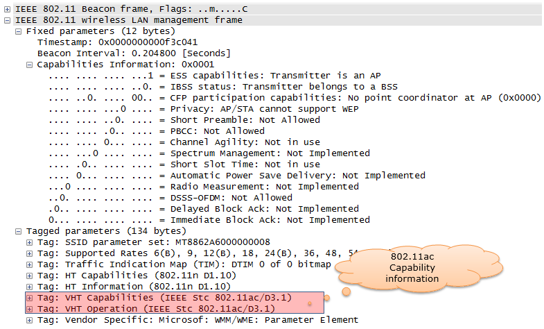
It may look simple two lines of information, but it will contain a lot of details of the 802.11ac capability that the AP supports. Following is the full decoded information.
Decoded Beacon tags,
Tag: VHT Capabilities (IEEE Stc 802.11ac/D3.1)
    Tag Number: VHT Capabilities (IEEE Stc 802.11ac/D3.1) (191)
    Tag length: 12
    VHT Capabilities Info: 0x03800022
        .... .... .... .... .... .... .... ..10 = Maximum MPDU Length: 11 454 (0x00000002)
        .... .... .... .... .... .... .... 00.. = Supported Channel Width Set: Neither 160MHz
                                                  nor 80+80 supported (0x00000000)
        .... .... .... .... .... .... ...0 .... = Rx LDPC: Not supported
        .... .... .... .... .... .... ..1. .... = Short GI for 80MHz: Supported
        .... .... .... .... .... .... .0.. .... = Short GI for 160MHz and 80+80MHz: Not supported
        .... .... .... .... .... .... 0... .... = Tx STBC: Not supported
        .... .... .... .... .... .000 .... .... = Rx STBC: None (0x00000000)
        .... .... .... .... .... 0... .... .... = SU Beam-former Capable: Not supported
        .... .... .... .... ...0 .... .... .... = SU Beam-formee Capable: Not supported
        .... .... .... .... 000. .... .... .... = Compressed Steering Number of Beamformer Antennas
                                                  Supported: 1 (0x00000000)
        .... .... .... .000 .... .... .... .... = Number of Sounding Dimensions: 1 (0x00000000)
        .... .... .... 0... .... .... .... .... = MU Beam-former Capable: Not supported
        .... .... ...0 .... .... .... .... .... = MU Beam-formee Capable: Not supported
        .... .... ..0. .... .... .... .... .... = VHT TXOP PS: Not supported
        .... .... .0.. .... .... .... .... .... = +HTC-VHT Capable (VHT variant HT Control field):
                                                  Not supported
        .... ..11 1... .... .... .... .... .... = Max A-MPDU Length: 1 048 575 (0x00000007)
        .... 00.. .... .... .... .... .... .... = VHT Link Adaptation: No Feedback (0x00000000)
        ...0 .... .... .... .... .... .... .... = Rx Antenna Pattern Consistency: Not supported
        ..0. .... .... .... .... .... .... .... = Tx Antenna Pattern Consistency: Not supported
        00.. .... .... .... .... .... .... .... = Reserved: False
    VHT Supported MCS Set
        Rx MCS Map: 0xfffe
            .... .... .... ..10 = Rx 1 SS: MCS 0-9 (0x0002)
            .... .... .... 11.. = Rx 2 SS: Not Supported (0x0003)
            .... .... ..11 .... = Rx 3 SS: Not Supported (0x0003)
            .... .... 11.. .... = Rx 4 SS: Not Supported (0x0003)
            .... ..11 .... .... = Rx 5 SS: Not Supported (0x0003)
            .... 11.. .... .... = Rx 6 SS: Not Supported (0x0003)
            ..11 .... .... .... = Rx 7 SS: Not Supported (0x0003)
            11.. .... .... .... = Rx 8 SS: Not Supported (0x0003)
        ...0 0000 0000 0000 = Rx Highest Long GI Data Rate (in Mb/s, 0 = subfield not in use):
           0x0000
        Tx MCS Map: 0xfffe
            .... .... .... ..10 = Tx 1 SS: MCS 0-9 (0x0002)
            .... .... .... 11.. = Tx 2 SS: Not Supported (0x0003)
            .... .... ..11 .... = Tx 3 SS: Not Supported (0x0003)
            .... .... 11.. .... = Tx 4 SS: Not Supported (0x0003)
            .... ..11 .... .... = Tx 5 SS: Not Supported (0x0003)
            .... 11.. .... .... = Tx 6 SS: Not Supported (0x0003)
            ..11 .... .... .... = Tx 7 SS: Not Supported (0x0003)
            11.. .... .... .... = Tx 8 SS: Not Supported (0x0003)
        ...0 0000 0000 0000 = Tx Highest Long GI Data Rate  (in Mb/s, 0 = subfield not in use):
           0x0000
Tag: VHT Operation (IEEE Stc 802.11ac/D3.1)
    Tag Number: VHT Operation (IEEE Stc 802.11ac/D3.1) (192)
    Tag length: 5
    VHT Operation Info
        Channel Width: 80 MHz (0x01)
        Channel Center Segment 0: 42
        Channel Center Segment 1: 0
    Basic MCS Map: 0xfffc
        .... .... .... ..00 = Basic 1 SS: MCS 0-7 (0x0000)
        .... .... .... 11.. = Basic 2 SS: Not Supported (0x0003)
        .... .... ..11 .... = Basic 3 SS: Not Supported (0x0003)
        .... .... 11.. .... = Basic 4 SS: Not Supported (0x0003)
        .... ..11 .... .... = Basic 5 SS: Not Supported (0x0003)
        .... 11.. .... .... = Basic 6 SS: Not Supported (0x0003)
        ..11 .... .... .... = Basic 7 SS: Not Supported (0x0003)
        11.. .... .... .... = Basic 8 SS: Not Supported (0x0003)
Let's read the key values in this capture. VHT Operation says Channel Width 80 MHz, and Channel Center Segment 0 is 42. Channel 42 is at 5000 + 5 x 42 = 5210 MHz, which is the center of the 80 MHz block made of channels 36, 40, 44 and 48. The Rx and Tx MCS Maps are 0xfffe, so the AP supports MCS 0-9 on one spatial stream only. The Basic MCS Map 0xfffc says that every station in this BSS must support at least MCS 0-7 on one stream. The screenshot above also shows a Beacon Interval of 0.2048 seconds, which is 200 TU of 1.024 ms each.
Two tags announce 802.11ac : VHT Capabilities, tag 191, says what the AP can do, and VHT Operation, tag 192, says how the BSS runs now.The MCS Map uses 2 bits per stream : 0 means MCS 0-7, 1 means MCS 0-8, 2 means MCS 0-9 and 3 means not supported, so 0xfffe is one stream with MCS 0-9.
Detecting 802.11ac Station - Device
Communication is the exchange of information between two or more parties. The previous section showed how the device can figure out the 802.11ac capability of AP. Then you would ask how the AP can figure out 802.11ac capability of the device. The AP can figure out the device capability from [Probe Request] message from the device as shown below.
Decoded Probe Request,
IEEE 802.11 Probe Request, Flags: ........C
    Type/Subtype: Probe Request (0x04)
    Frame Control Field: 0x4000
        .... ..00 = Version: 0
        .... 00.. = Type: Management frame (0)
        0100 .... = Subtype: 4
        Flags: 0x00
            .... ..00 = DS status: Not leaving DS or network is operating in AD-HOC mode
                        (To DS: 0 From DS: 0) (0x00)
            .... .0.. = More Fragments: This is the last fragment
            .... 0... = Retry: Frame is not being retransmitted
            ...0 .... = PWR MGT: STA will stay up
            ..0. .... = More Data: No data buffered
            .0.. .... = Protected flag: Data is not protected
            0... .... = Order flag: Not strictly ordered
    .000 0000 0011 1100 = Duration: 60 microseconds
    Receiver address: Anritsu_07:91:0e (00:00:91:07:91:0e)
    Destination address: Anritsu_07:91:0e (00:00:91:07:91:0e)
    Transmitter address: e0:cb:ee:f9:4a:de (e0:cb:ee:f9:4a:de)
    Source address: e0:cb:ee:f9:4a:de (e0:cb:ee:f9:4a:de)
    BSS Id: Anritsu_07:91:0e (00:00:91:07:91:0e)
    Fragment number: 0
    Sequence number: 2048
    Frame check sequence: 0xfe06c6aa [correct]
        [Good: True]
        [Bad: False]
IEEE 802.11 wireless LAN management frame
    Tagged parameters (83 bytes)
        Tag: SSID parameter set: MT8862A6000000008
            Tag Number: SSID parameter set (0)
            Tag length: 17
            SSID: MT8862A6000000008
        Tag: Supported Rates 6, 9, 12, 18, 24, 36, 48, 54, [Mbit/sec]
            Tag Number: Supported Rates (1)
            Tag length: 8
            Supported Rates: 6 (0x0c)
            Supported Rates: 9 (0x12)
            Supported Rates: 12 (0x18)
            Supported Rates: 18 (0x24)
            Supported Rates: 24 (0x30)
            Supported Rates: 36 (0x48)
            Supported Rates: 48 (0x60)
            Supported Rates: 54 (0x6c)
        Tag: DS Parameter set: Current Channel: 36
            Tag Number: DS Parameter set (3)
            Tag length: 1
            Current Channel: 36
        Tag: HT Capabilities (802.11n D1.10)
            Tag Number: HT Capabilities (802.11n D1.10) (45)
            Tag length: 26
            HT Capabilities Info: 0x01ef
                .... .... .... ...1 = HT LDPC coding capability:
                                      Transmitter supports receiving LDPC coded packets
                .... .... .... ..1. = HT Support channel width: Transmitter supports 20MHz and
                                      40MHz operation
                .... .... .... 11.. = HT SM Power Save: SM Power Save disabled (0x0003)
                .... .... ...0 .... = HT Green Field: Transmitter is not able to receive PPDUs
                                      with Green Field (GF) preamble
                .... .... ..1. .... = HT Short GI for 20MHz: Supported
                .... .... .1.. .... = HT Short GI for 40MHz: Supported
                .... .... 1... .... = HT Tx STBC: Supported
                .... ..01 .... .... = HT Rx STBC: Rx support of one spatial stream (0x0001)
                .... .0.. .... .... = HT Delayed Block ACK: Transmitter does not support
                                      HT-Delayed BlockAck
                .... 0... .... .... = HT Max A-MSDU length: 3839 bytes
                ...0 .... .... .... = HT DSSS/CCK mode in 40MHz: Won't/Can't use of DSSS/CCK
                                      in 40 MHz
                ..0. .... .... .... = HT PSMP Support: Won't/Can't support PSMP operation
                .0.. .... .... .... = HT Forty MHz Intolerant: Use of 40 MHz transmissions
                                      unrestricted/allowed
                0... .... .... .... = HT L-SIG TXOP Protection support: Not supported
            A-MPDU Parameters: 0x03
                .... ..11 = Maximum Rx A-MPDU Length: 0x03 (65535[Bytes])
                ...0 00.. = MPDU Density: no restriction (0x00)
                000. .... = Reserved: 0x00
            Rx Supported Modulation and Coding Scheme Set: MCS Set
                Rx Modulation and Coding Scheme (One bit per modulation): 2 spatial streams
                    .... .... .... .... .... .... 1111 1111 = Rx Bitmask Bits 0-7: 0x000000ff
                    .... .... .... .... 1111 1111 .... .... = Rx Bitmask Bits 8-15: 0x000000ff
                    .... .... 0000 0000 .... .... .... .... = Rx Bitmask Bits 16-23: 0x00000000
                    0000 0000 .... .... .... .... .... .... = Rx Bitmask Bits 24-31: 0x00000000
                    .... .... .... .... .... .... .... ...0 = Rx Bitmask Bit 32: 0x00000000
                    .... .... .... .... .... .... .000 000. = Rx Bitmask Bits 33-38: 0x00000000
                    .... .... ...0 0000 0000 0000 0... .... = Rx Bitmask Bits 39-52: 0x00000000
                    ...0 0000 0000 0000 0000 0000 000. .... = Rx Bitmask Bits 53-76: 0x00000000
                .... ..00 0000 0000 = Highest Supported Data Rate: 0x0000
                .... .... .... ...0 = Tx Supported MCS Set: Not Defined
                .... .... .... ..0. = Tx and Rx MCS Set: Equal
                .... .... .... 00.. = Maximum Number of Tx Spatial Streams Supported: 0x0000,
                                      TX MCS Set Not Defined
                .... .... ...0 .... = Unequal Modulation: Not supported
            HT Extended Capabilities: 0x0000
                .... .... .... ...0 = Transmitter supports PCO: Not supported
                .... .... .... .00. = Time needed to transition between 20MHz and 40MHz:
                                      No Transition (0x0000)
                .... ..00 .... .... = MCS Feedback capability: STA does not provide MCS feedback
                                      (0x0000)
                .... .0.. .... .... = High Throughput: Not supported
                .... 0... .... .... = Reverse Direction Responder: Not supported
            Transmit Beam Forming (TxBF) Capabilities: 0x0000
                .... .... .... .... .... .... .... ...0 = Transmit Beamforming: Not supported
                .... .... .... .... .... .... .... ..0. = Receive Staggered Sounding: Not supported
                .... .... .... .... .... .... .... .0.. = Transmit Staggered Sounding:
                                                          Not supported
                .... .... .... .... .... .... .... 0... = Receive Null Data packet (NDP):
                                                          Not supported
                .... .... .... .... .... .... ...0 .... = Transmit Null Data packet (NDP):
                                                          Not supported
                .... .... .... .... .... .... ..0. .... = Implicit TxBF capable: Not supported
                .... .... .... .... .... .... 00.. .... = Calibration: incapable (0x00000000)
                .... .... .... .... .... ...0 .... .... = STA can apply TxBF using CSI explicit
                                                          feedback: Not supported
                .... .... .... .... .... ..0. .... .... = STA can apply TxBF using uncompressed
                                                     beamforming feedback matrix: Not supported
                .... .... .... .... .... .0.. .... .... = STA can apply TxBF using compressed
                                                     beamforming feedback matrix: Not supported
                .... .... .... .... ...0 0... .... .... = Receiver can return explicit CSI
                                                     feedback: not supported (0x00000000)
                .... .... .... .... .00. .... .... .... = Receiver can return explicit uncompressed
                                           Beamforming Feedback Matrix: not supported (0x00000000)
                .... .... .... ...0 0... .... .... .... = STA can compress and use compressed
                                           Beamforming Feedback Matrix: not supported (0x00000000)
                .... .... .... .00. .... .... .... .... = Minimal grouping used for explicit
                                           feedback reports: No grouping supported (0x00000000)
                .... .... ...0 0... .... .... .... .... = Max antennae STA can support when CSI
                                            feedback required: 1 TX antenna sounding (0x00000000)
                .... .... .00. .... .... .... .... .... = Max antennae STA can support
                                            when uncompressed Beamforming feedback required:
                                            1 TX antenna sounding (0x00000000)
                .... ...0 0... .... .... .... .... .... = Max antennae STA can support
                                            when compressed Beamforming feedback required:
                                            1 TX antenna sounding (0x00000000)
                .... .00. .... .... .... .... .... .... = Maximum number of rows of CSI explicit
                                            feedback: 1 row of CSI (0x00000000)
                ...0 0... .... .... .... .... .... .... = Maximum number of space time streams for
                                            which channel dimensions can be simultaneously
                                            estimated: 1 space time stream (0x00000000)
                000. .... .... .... .... .... .... .... = Reserved: 0x00000000
            Antenna Selection (ASEL) Capabilities: 0x00
                .... ...0 = Antenna Selection Capable: Not supported
                .... ..0. = Explicit CSI Feedback Based Tx ASEL: Not supported
                .... .0.. = Antenna Indices Feedback Based Tx ASEL: Not supported
                .... 0... = Explicit CSI Feedback: Not supported
                ...0 .... = Antenna Indices Feedback: Not supported
                ..0. .... = Rx ASEL: Not supported
                .0.. .... = Tx Sounding PPDUs: Not supported
                0... .... = Reserved: 0x00
        Tag: Vendor Specific: Microsof: Unknown 8
            Tag Number: Vendor Specific (221)
            Tag length: 7
            OUI: 00-50-f2 (Microsof)
            Vendor Specific OUI Type: 8
            Type: Unknown (0x08)
        Tag: VHT Capabilities (IEEE Stc 802.11ac/D3.1)
            Tag Number: VHT Capabilities (IEEE Stc 802.11ac/D3.1) (191)
            Tag length: 12
            VHT Capabilities Info: 0x338051b2
                .... .... .... .... .... .... .... ..10 = Maximum MPDU Length: 11 454 (0x00000002)
                .... .... .... .... .... .... .... 00.. = Supported Channel Width Set:
                                                   Neither 160MHz nor 80+80 supported (0x00000000)
                .... .... .... .... .... .... ...1 .... = Rx LDPC: Supported
                .... .... .... .... .... .... ..1. .... = Short GI for 80MHz: Supported
                .... .... .... .... .... .... .0.. .... = Short GI for 160MHz and 80+80MHz:
                                                          Not supported
                .... .... .... .... .... .... 1... .... = Tx STBC: Supported
                .... .... .... .... .... .001 .... .... = Rx STBC: 1 Spatial Stream Supported
                                                          (0x00000001)
                .... .... .... .... .... 0... .... .... = SU Beam-former Capable: Not supported
                .... .... .... .... ...1 .... .... .... = SU Beam-formee Capable: Supported
                .... .... .... .... 010. .... .... .... = Compressed Steering Number of Beamformer
                                                          Antennas Supported: 3 (0x00000002)
                .... .... .... .000 .... .... .... .... = Number of Sounding Dimensions: 1
                                                          (0x00000000)
                .... .... .... 0... .... .... .... .... = MU Beam-former Capable: Not supported
                .... .... ...0 .... .... .... .... .... = MU Beam-formee Capable: Not supported
                .... .... ..0. .... .... .... .... .... = VHT TXOP PS: Not supported
                .... .... .0.. .... .... .... .... .... = +HTC-VHT Capable (VHT variant HT Control
                                                          field): Not supported
                .... ..11 1... .... .... .... .... .... = Max A-MPDU Length:1 048 575 (0x00000007)
                .... 00.. .... .... .... .... .... .... = VHT Link Adaptation: No Feedback
                                                          (0x00000000)
                ...1 .... .... .... .... .... .... .... = Rx Antenna Pattern Consistency:Supported
                ..1. .... .... .... .... .... .... .... = Tx Antenna Pattern Consistency:Supported
                00.. .... .... .... .... .... .... .... = Reserved: False
            VHT Supported MCS Set
                Rx MCS Map: 0xfffa
                    .... .... .... ..10 = Rx 1 SS: MCS 0-9 (0x0002)
                    .... .... .... 10.. = Rx 2 SS: MCS 0-9 (0x0002)
                    .... .... ..11 .... = Rx 3 SS: Not Supported (0x0003)
                    .... .... 11.. .... = Rx 4 SS: Not Supported (0x0003)
                    .... ..11 .... .... = Rx 5 SS: Not Supported (0x0003)
                    .... 11.. .... .... = Rx 6 SS: Not Supported (0x0003)
                    ..11 .... .... .... = Rx 7 SS: Not Supported (0x0003)
                    11.. .... .... .... = Rx 8 SS: Not Supported (0x0003)
                ...0 0011 0000 1100 = Rx Highest Long GI Data Rate
                                     (in Mb/s, 0 = subfield not in use): 0x030c
                Tx MCS Map: 0xfffa
                    .... .... .... ..10 = Tx 1 SS: MCS 0-9 (0x0002)
                    .... .... .... 10.. = Tx 2 SS: MCS 0-9 (0x0002)
                    .... .... ..11 .... = Tx 3 SS: Not Supported (0x0003)
                    .... .... 11.. .... = Tx 4 SS: Not Supported (0x0003)
                    .... ..11 .... .... = Tx 5 SS: Not Supported (0x0003)
                    .... 11.. .... .... = Tx 6 SS: Not Supported (0x0003)
                    ..11 .... .... .... = Tx 7 SS: Not Supported (0x0003)
                    11.. .... .... .... = Tx 8 SS: Not Supported (0x0003)
                ...0 0011 0000 1100 = Tx Highest Long GI Data Rate
                                      (in Mb/s, 0 = subfield not in use): 0x030c
Compare this Probe Request with the Beacon above. The device supports MCS 0-9 on two spatial streams, because its MCS Maps are 0xfffa. Its Rx Highest Long GI Data Rate is 0x030c, which is 780 Mb/s. That is exactly 2 x 234 x 8 x 5/6 / 4.0 microseconds, the rate of two streams of MCS 9 at 80 MHz with the long GI. The device is an SU Beam-formee, but not an MU Beam-formee, so an AP can steer beams to it only in SU mode. It also supports Rx LDPC, which the AP in the Beacon above does not.
The AP learns the device from the Probe Request : the same VHT Capabilities tag appears in both directions.The link uses what both sides support : here the AP limits the link to one stream, although the device supports two.
VHT - Very High Throughput
One of the most important keywords in 802.11ac would VHT. VHT stands for Very High Throughput. You would not need any additional explanation on what this means. The meaning is obvious and self-explanatory.
The question is how to achieve VHT and what kind of new frames and protocols are introduced to implement this.
The VHT is a Physical layer frame concept which is defined as shown below.
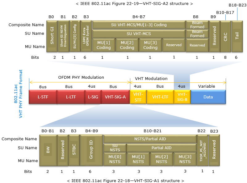
Legacy part : L-STF, L-LTF and L-SIG take 8 + 8 + 4 = 20 microseconds and use the OFDM PHY modulation of 802.11a. Every 5 GHz station can decode them.VHT-SIG-A : two 24-bit symbols, 8 microseconds in total. VHT-SIG-A1 carries BW, STBC, Group ID and NSTS/Partial AID. VHT-SIG-A2 carries Short GI, the coding bits, SU VHT-MCS and Beamformed, protected by an 8-bit CRC.VHT part : VHT-STF, VHT-LTF and VHT-SIG-B use VHT modulation. The length of VHT-LTF grows with the number of space-time streams, so 8 microseconds in the picture is one case.Data : variable length, and the only part that runs at the VHT-MCS in VHT-SIG-A2.
One detail in the upper drawing is inconsistent. The bit positions B0, B1, B2 and B3 are one bit each, and B0 to B23 add up to 24 bits. But the Bits row gives 2 for Short GI and 6 for LDPC Extra OFDM Symbol, and the row then adds up to 30. Read these two fields as 1 bit each. The VHT-SIG-A1 row below is consistent and adds up to 24 bits.
In wireshark log, you may see this framing information from Radiotap Header as shown below.
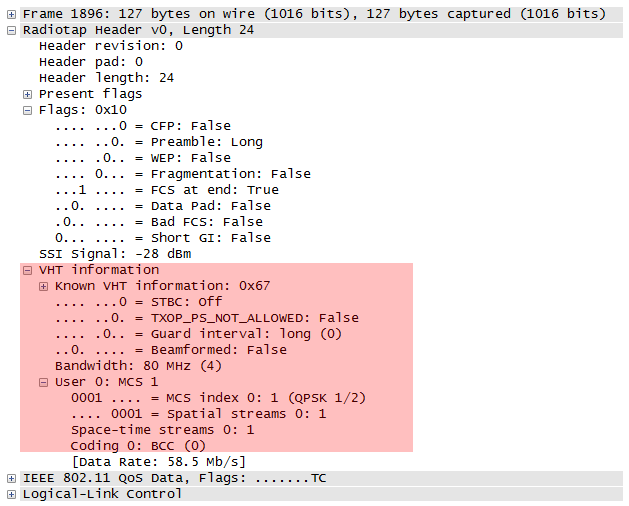
You can check the Data Rate that Wireshark prints from the other fields. The frame uses 80 MHz, so it has 234 data subcarriers. MCS 1 is QPSK with rate 1/2, so each subcarrier carries 2 x 1/2 = 1 data bit per symbol. There is one spatial stream, and the long guard interval gives a 4.0 microsecond symbol. So the rate is 234 x 1 / 4.0 = 58.5 Mb/s, the value in the capture. The table below applies the same formula to MCS 9, which is 256 QAM with rate 5/6, for one stream.
Bandwidth |
Data subcarriers |
MCS 9, 1 stream, 800 ns GI |
MCS 9, 1 stream, 400 ns GI |
40 MHz | 108 | 180.0 Mbps | 200.0 Mbps |
80 MHz | 234 | 390.0 Mbps | 433.3 Mbps |
160 MHz | 468 | 780.0 Mbps | 866.7 Mbps |
The 20 MHz row is missing for a reason. A 20 MHz channel has 52 data subcarriers, so one stream of MCS 9 would carry 52 x 8 x 5/6 = 346.67 data bits per symbol. That is not a whole number of bits, so MCS 9 is not used at 20 MHz with one stream. With three streams the count is 1040 bits, and the combination becomes usable.
The preamble starts in legacy format : an 802.11a or 802.11n station decodes L-SIG and learns how long the PPDU lasts.VHT-SIG-A tells the receiver how to decode the rest : bandwidth, streams, MCS, coding and guard interval all come from it.The rate follows from four numbers : data subcarriers, bits per subcarrier after coding, streams and symbol time.
Dynamic Bandwidth Allocation
802.11ac support various types of bandwidth combination like 20 Mhz, 80 Mhz, 160 Mhz. Then the question would 'how do they allocate the bandwidth ?'. Statically or Dynamically ?
Static allocation means that Transmitter (Initiator) and Reciever(Responder) negotiate and determines the bandwidth during early stage of connection setup and keep it same until the end of communication (a session).
Dynamic allocation means that Transmitter and Reciever SOMEHOW negotiate/determine the bandwidth in very short interval even during a single session.
802.11ac picked up the dynamic allocation approach. It allows the change of the bandwidth at every transmission.
Then the question is 'HOW ?'. What kind of negotiation they use to determine/agree upon the bandwidth between Transmitter and Reciever ?
Basic Idea is simple. As you see in Data Transmission in Detail section, basic channel acquisition process for all 802.11 is based on RTS/CTS mechanism. 802.11ac use the same mechanism to determine the avaiable bandwidth dynamically. The idea is to split the whole possible 802.11ac band into multiple blocks of basic segments (e.g, 20 Mhz, 40 Mhz, 80 Mhz etc) and perform the multiple RTS/CTS simulateneously across the multiple frequency block. (It is very similary for Carrier Aggregation in LTE). First, the initiator sends multiple RTS accross the multiple frequency block and wait for CTS. If the initiator recieves CTS accross the all the blocks, it can use all the frequency blocks (very wide aggregated bandwidth). If the initiator recieves only a few CTS for the all transmitted RTS, it uses the smaller bandwidth for which CTS is recieved. (Refer to Ref [9] for the details).
Let me give you a couple of examples with illustration on how Dynamic Bandwidth goes. Here goes only two cases but there can be much more variations on this.
This is the case where there is no interference between Node A(initiator) and Node B(recipient) and the full bandwith is avaiable for both nodes. Of course, these nodes does not know anything about the bandwidth availability before it completes step 3.
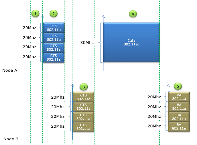
- Step 0 : Right before Step 1, it is assumed that Node A split the whole 80 Mhz section into 4 contiguous 20 Mhz block and performed carrier sensing for each of these 20 Mhz block. And it is assumed that all of these 20 Mhz block turned out to be available.
- Step 1 : Node A wait for a certain time period called DIFS(DCF Inter Frame Space), assuming that the scheduling is done in DCF.
- Step 2 : Node A transmit RTS for each of 20 Mhz block to Node B using 802.11a frame and it is assumed that all of these RTS reached Node B successfully.
- Step 3 : (Assuming that Node B detected RTS for all of 20 Mhz blocks) Node B transmit CTS using 802.11a frame for every 20 Mhz subblocks.
- Step 4 : (Assuming that Node A detected CTS for all of 20 Mhz blocks) Node A assumes that all 80Mhz BW is clear/no-interference and transmit the data in 802.11ac mode utilizing the full 80 Mhz.
- Step 5 : (Assuming that Node B received and decoded the whole data) Node B sends Ack for every 20 Mhz blocks (80 Mhz in total).
This is the case where there is some interference in some spectrum blocks within the 80 Mhz block on Node B(recipient). Of course, these nodes does not know anything about the bandwidth availability before it completes step 3.
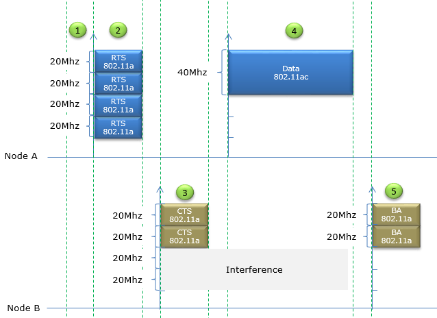
- Step 0 : Right before Step 1, it is assumed that Node A split the whole 80 Mhz section into 4 contiguous 20 Mhz block and performed carrier sensing for each of these 20 Mhz block. And it is assumed that all of these 20 Mhz block turned out to be available.
- Step 1 : Node A wait for a certain time period called DIFS(DCF Inter Frame Space), assuming that the scheduling is done in DCF.
- Step 2 : Node A transmit RTS for each of 20 Mhz block to Node B using 802.11a frame.
- Step 3 : (In various reason, e.g, Node B failed to receive RTS due to interference or Medium is busy based on carrier sensing ) Node B transmit CTS using 802.11a frame for only two consecutive 20 Mhz blocks.
- Step 4 : (Assuming that Node A detected CTS for the two 20 Mhz blocks) Node A assumes that only 40Mhz BW is clear/no-interference and transmit the data in 802.11ac mode utilizing the 40 Mhz.
- Step 5 : (Assuming that Node B received and decoded the whole data) Node B sends Ack for the two 20 Mhz blocks (40 Mhz in total).
Additional MAC Frame Types
In 802.11ac, Following new Frame Types are added to the existing type. Most of New Frametype is for impelementing Channel Measurement and Report to perform MU-MIMO Beamforming.
The table below lists only control frames, with Type 01. The Subtype values are 4-bit binary numbers, so 0100 is Subtype 4 and 0101 is Subtype 5. Both new frames are short, because a control frame has no frame body beyond a few fixed fields. The third frame of the sounding sequence is different. The VHT Compressed Beamforming frame carries a large feedback report, so it is not a control frame. It is a management Action frame with Category VHT, which is category code 21, and VHT Action 0.
The Reserved row is true for 802.11ac, but later amendments have used two of these values. Wireshark decodes Subtype 0010 as the Trigger frame of 802.11ax and Subtype 0011 as the S1G TWT Ack of 802.11ah. So a newer capture can show control Subtypes that this table calls Reserved.
|
Type |
Type Description |
Sub Type |
Sub Type Description |
|
01 |
Control |
0000-0011 |
Reserved (This is changed from existing field) |
|
01 |
Control |
0100 |
|
|
01 |
Control |
0101 |
Two new control frames : Beamforming Report Poll is Subtype 0100 and VHT NDP Announcement is Subtype 0101.The report itself is an Action frame : VHT Compressed Beamforming is Category 21, VHT Action 0.
Beamforming Report Poll Frame
The AP can collect feedback from only one beamformee at a time. So after the first beamformee has answered the sounding, the AP polls each of the other beamformees in turn, and this frame is the poll. It also solves a second problem, which is a lost part of a long report.
The diagram below shows a short control frame. It has the usual MAC header with Frame Control, Duration, RA and TA, then one octet of Feedback Segment Retransmission Bitmap, then the FCS.
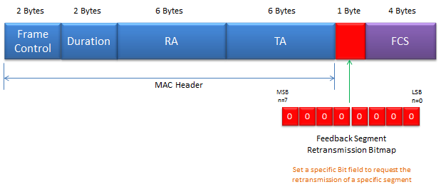
MAC header : 2 + 2 + 6 + 6 = 16 octets. RA is the beamformee being polled and TA is the beamformer.Feedback Segment Retransmission Bitmap : bit n asks for feedback segment n, from n = 0 at the LSB to n = 7 at the MSB, as the note in the picture says.Frame length : 16 + 1 + 4 = 21 octets in total.
Why would a report need segments at all? Let's size a large one. With 8 transmit antennas and 8 columns, the feedback matrix has 56 angles per subcarrier. With the MU codebook of 9 bits for each phi angle and 7 bits for each psi angle, that is 448 bits per subcarrier. At 160 MHz without grouping, the beamformee reports 468 subcarriers, so the matrix alone is 448 x 468 = 209,664 bits, or 26,208 octets. The captures above show a Maximum MPDU Length of 11,454 octets. So the report does not fit in one MPDU, and the beamformee splits it into segments.
The VHT MIMO Control field counts the segments in its 3-bit Remaining Feedback Segments subfield, so a report has at most 8 segments. That matches the 8 bits of the bitmap. If some segments are lost, the AP sets only their bits in the next poll, and the beamformee sends only those segments again.
The poll gives each beamformee its turn : the first beamformee answers the NDP directly, and the others wait for a Beamforming Report Poll.A large report travels in up to 8 segments : the bitmap asks for a repeat of only the segments that were lost.
VHT NDP Announcement
This frame is used for BeamFormer (AP) to initiate Channel Measurement Process. (Refer to 802.11ac 8.3.1.20 VHT NDP Announcement frame format for the details) It tells the stations which of them must measure the NDP that follows, and what kind of feedback each one must return.
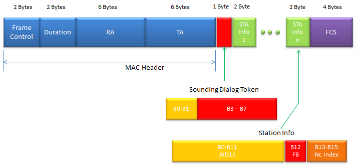
MAC header : 16 octets. With one STA Info field, RA is the address of that station. With more than one, RA is the broadcast address.Sounding Dialog Token : 1 octet. The beamformee copies the token number into its report, so the AP can match each report to its sounding.STA Info : 2 octets per station, with AID12, the Feedback Type bit FB and Nc Index, as the table below describes.
The picture labels the token octet as B0-B1 and B3-B7, so bit B2 is missing. The Wireshark dissector decodes B0-B1 as the NDP Announcement Variant and B2-B7 as the 6-bit Sounding Dialog Token. The value 0 of the variant means VHT, while later amendments use other values for HE, EHT and ranging. The frame size follows from the fields. For example, an announcement for three stations is 16 + 1 + 3 x 2 + 4 = 27 octets.
< Field Description of Station Info >
|
Field |
Description |
|
AID12 (B0-B11) |
The 12 least significant bits of the AID of a STA expected to process the following VHT NDP and prepare the sounding feedback. Set to be 0 if the STA is an AP, mesh STA, or STA that is a member of an IBSS |
|
Feedback Type (B12) |
The type of feedback requested. Set to 0 for SU. Set to 1 for MU. |
|
Nc Index (B13-B15) |
This applies only when Feedback type is 1(MU) It indicates the number of columns, Nc, in the Compressed Beamforming Feedback Matrix Set to 0 to request Nc = 1 Set to 1 to request Nc = 2
Set to 7 to request Nc = 8 |
VHT Compressed Beamforming Frame
This frame is used for BeamFormee (user) to report channel measurement result (Refer to 802.11ac 8.5.23.2 VHT Compressed Beamforming frame format for the details) It is the answer to the sounding, and it is by far the largest frame in the sequence.
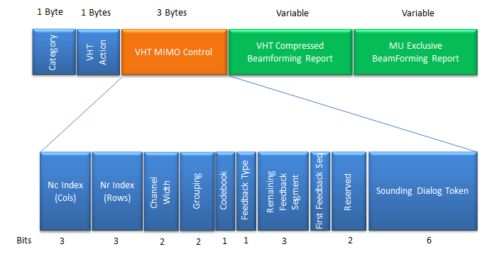
Category and VHT Action : 1 octet each, with Category 21 for VHT and Action 0 for VHT Compressed Beamforming.VHT MIMO Control : 3 octets that describe the report. Nc Index and Nr Index give the columns and rows minus one. Channel Width is 0 to 3 for 20, 40, 80 and 160 MHz. Grouping is 0, 1 or 2 for Ng = 1, 2 or 4. Feedback Type is 0 for SU and 1 for MU. The 6-bit Sounding Dialog Token repeats the token of the NDP Announcement.VHT Compressed Beamforming Report : one average SNR octet per column, then the angles of the feedback matrix for every reported subcarrier.MU Exclusive Beamforming Report : present only for MU feedback. It adds a Delta SNR for each column on a subset of subcarriers.
The word compressed refers to the angles. The beamformee does not send the matrix V as complex numbers. It sends Givens rotation angles, called phi and psi, from which the beamformer rebuilds V. The bits per angle depend on the Feedback Type and on the Codebook bit. For SU feedback they are 2 bits for psi and 4 for phi, or 4 and 6. For MU feedback they are 5 and 7, or 7 and 9. MU needs finer angles, because the AP uses them to cancel the interference between users.
Let's size a typical report. A 4-antenna AP sounds a 2-stream device at 80 MHz. So Nr = 4 and Nc = 2, and the matrix has 5 phi and 5 psi angles per subcarrier. With the SU codebook of 6 and 4 bits, that is 50 bits per subcarrier. Without grouping, the device reports 234 subcarriers, so the matrix takes 11,700 bits, about 1,463 octets. With Ng = 4, it reports only 62 subcarriers, and the matrix shrinks to 3,100 bits, about 388 octets. Grouping therefore cuts the airtime of the feedback almost four times, at the cost of coarser steering.
VHT MIMO Control tells the AP how to parse the report : dimensions, bandwidth, grouping, codebook and feedback type are all in its 3 octets.Angles instead of matrices : phi and psi angles keep the report small enough to send after every sounding.Grouping and codebook trade feedback size against accuracy : MU feedback uses the finer codebook.
VHT preamble format for sounding PPDUs
Refer to 802.11ac Table 22-4Fields of the VHT PPDU for each field label. The NDP that the beamformer sends in the sounding sequence is a VHT PPDU with a preamble and no Data field, and the beamformee measures the channel from its training fields.
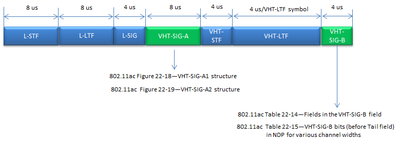
Same fields as a data PPDU : L-STF, L-LTF, L-SIG, VHT-SIG-A, VHT-STF, VHT-LTF and VHT-SIG-B, as in the VHT PPDU of the VHT section above.No Data field : the NDP ends after VHT-SIG-B, which is why it is called a Null Data Packet.VHT-LTF at 4 microseconds per symbol : these are the training symbols. The beamformee estimates the channel from every sounded transmit chain with them.
Let's add up the length of an NDP with 4 VHT-LTF symbols. The fixed fields take 8 + 8 + 4 + 8 + 4 = 32 microseconds, the VHT-LTF part takes 4 x 4 = 16 and VHT-SIG-B takes 4. So the NDP lasts 52 microseconds. It carries no user data, so this time is part of the sounding overhead that the NOTE in the next section talks about.
The NDP is only a preamble : all its value is in the VHT-LTF symbols.More antennas mean a longer NDP : each extra VHT-LTF symbol adds 4 microseconds.
Channel measurement - sounding - procedures
To perform proper beamforming for specific devices, it is crucial to figure out accurate channel condition between BeamFormer and BeanFormee. To figure out the channel condition, BeamFormer and BeamFormee performs a specific sequence of calibration process and this process is called Channel Measurement or Sounding process. It goes as follows.
Refer to 802.11ac 9.31.5.2 Rules for VHT sounding protocol sequences, Figure 9-41a and Figure 9-41a for the details.
- Step 1 : BeamFormer (usually AP) transmit NDP(Null Data Packet) Announcement frame
- Step 2 : BeamFormee (usually WLAN user device) receives NDP announcement and waits for the NDP without responding (Other device that are not sepecified in NDP defer channel access until the channel measurement process is complete)
- Step 3 : Beamformer transmit Null Data Packet carrying Training Sequence (NDP Frame, VHT preamble format)
- Step 4 : BeamFormee analyze the training sequence and send feedback Matrix (Refer to 802.11ac 8.4.1.48 VHT Compressed Beamforming Report field for the details of the feedback matrix)
- Step 5 : BeamFormer calculate the steering matrix based on the feedback matrix
- Step 1 : BeamFormer (usually AP) transmit NDP(Null Data Packet) Announcement frame
- Step 2 : BeamFormee (usually WLAN user device) receives NDP announcement and waits for the NDP without responding (Other device that are not sepecified in NDP defer channel access until the channel measurement process is complete)
- Step 3 : Beamformer transmit Null Data Packet carrying Training Sequence (NDP Frame, VHT preamble format)
- Step 4 : BeamFormees analyze the training sequence
- Step 5 : BeamFormee1 send send feedback Matrix (Refer to 802.11ac 8.4.1.48 VHT Compressed Beamforming Report field for the details of the feedback matrix)
- Step 6 : BeamFormer send BeamForming Report Poll for next BeamFormee
- Step 7 : The next BeamFormee send send feedback Matrix
- Step 8 : Repeat Step 6,7 until BeamFormer get all the information for all BeamFormees.
- Step 9 : BeamFormer calculate the steering matrix based on the feedback matrix
MU-MIMO BeamForming
MU-MIMO stands for Multi User MIMO and this is adopted only in 802.11ac (not in 802.11n and lower). When we say MIMO(Multi Input Multi Output), it normally mean SU-MIMO(Single User MIMO), which is a MIMO targeted to only one device(user). On the contrary, MU-MIMO is the MIMO targeted to multiple user simulateneously. It mean that in MU-MIMO the transmitter (Access Point) can transmite the multiple stream of data targeted to multiple user.
It sounds fancy, right ? However, the implementation of this technology would not be as easy as it sound and real performance would not be as good as expected. Probably it would need to go through a long way of evolution. Let's think of some of the challenges and possible issues related to MU-MIMO
- In order to the best optimized beam to each of users, it needs very accurately estimated radio channel information for each users.
- Usually to have the proper channel estimation for each users, the AP would require some channel quality information from each users(devices), this process would some overhead in terms of signaling or data communication.
- Since the multiple beams for multiple users are being transmitted simultaneously, there is always chances for one beam to interfere other beams. So it would be difficult to apply the very high order modulation schedule (e.g, 64 QAM or 256 QAM).
- To make a better pointed beam for a device, it require many antenna for the beam forming. Considering the fact that we would have 8 antenna maximum, I am not so confident on how well formed beam we can generate for multiple users (especially the number of user increases).
Putting aside the practical feasibility of this MU-MIMO, the specification is done. In most case of technology (even though it is not all the case), once the specification is issued the technology continues to evolve and get better and better.
802.11ac MU-MIMO Beamforming is expressed in a mathematical expression as follows (this is based on 802.11ac 22.3.11 SU-MIMO and DL-MU-MIMO Beamforming)
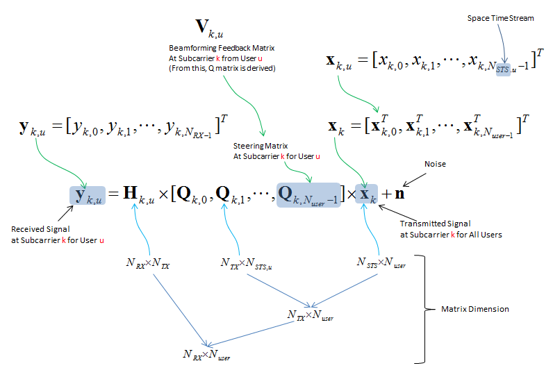
yk,u : the signal that user u receives on subcarrier k, one entry per receive antenna.Qk,u : the steering matrix for user u. The AP derives it from Vk,u, the feedback matrix that user u sends in the VHT Compressed Beamforming frame.xk : the space-time streams of all users stacked together, so the other users' streams reach user u only through Hk,u Qk,v. That product is the interference that good steering keeps small.
Compatibility
Whenever a new version of any technology comes out, one of the most concerning thing is compatibility. Can this new stuff work with all of those old stuffs out there already ? You would have the same questions about 802.11ac. Is 802.11ac compatitle with the existing (previous) techology (e.g, 802.11a and 802.11n) ? The answer is Yes. 802.11ac is designed from beginning to be compatible with 802.11a / n both for Access point and devices.
Let's see how the design keeps that promise, because several pieces on this page exist for this reason. First, every VHT PPDU starts with L-STF, L-LTF and L-SIG in the 802.11a format. An 802.11a or 802.11n station cannot decode the VHT part, but it decodes L-SIG, computes how long the PPDU lasts and stays silent until it ends. Second, RTS and CTS in the Dynamic Bandwidth cases are sent as 802.11a frames on every 20 MHz block. So a legacy station on any of those blocks sets its NAV. Third, the VHT Capabilities and VHT Operation tags are new elements in Beacons and Probe frames. A legacy station ignores elements it does not know, and an 802.11n station simply associates with an 802.11ac AP as an 802.11n station.
The limit is the band. 802.11ac works only in 5 GHz, so a 2.4 GHz device still needs 802.11n or older. For this reason, most 802.11ac APs are dual-band, with an 802.11n radio for 2.4 GHz.
The legacy preamble protects old stations : they read L-SIG and defer for the whole VHT PPDU.Duplicate RTS/CTS protects every 20 MHz block : legacy stations on the secondary channels also set their NAV.Mixed networks run at mixed rates : each station uses the highest mode that both it and the AP support.
Reference
[3] Understanding IEEE 802.11ac VHT Wireless
[4] 802.11ac Testing with the Vector Signal Transceiver
[5] Gigabit Wi-Fi 802.11ac In Depth (YouTube)
[6] 802.11ac Gigabit WiFi: Fact vs. Fiction (YouTube)
[7] Demonstrating the Performance of the Aruba Networks 802.11ac (YouTube)
[8] Aruba Controller-based and Controllerless Wi-Fi (YouTube)
[9] 802.11ac : A Survival Guide - Chapter 3. The MAC
[10] 802.11ac Wireless Packet Captures
[11] Deploying, Testing, and Tuning 802.11ac
[12] How to validate the WI-FI Information within Wireshark Part I: Determining the WLAN capabilities
[13] 802.11ac: The Fifth Generation of Wi-Fi Technical White Paper
[14] packet-ieee80211.c : Wireshark 802.11 dissector - VHT MIMO Control, NDP Announcement, Beamforming Report Poll and control subtype definitions