5G/NR System Architecture is almost same as LTE System Architecture. If you are already familiar with LTE protocol stack or general concept of radio protocol stack, you would not need to spend too much time in reading this page. Just take a brief look at the various figures / diagrams shown in this page would be enough. If you are new to the concept of LTE/NR radio protocol stack, I would suggest you to go through this page whenever you have chance and try to form your own big picture.
I would not describe much details on each component of the protocol stack in this page. It is too much to describe everything in a single page. The purpose of this page is to provide you with some big picture or intuitive understanding of the radio protocol stack. Most of the fundamental idea in this page comes from 3GPP 38.300 (Radio Access) and 23.501(NAS/Core Network).
- High Level Overview
- Message Flow across the System
- System Component and Specification Mapping
- L2 Radio Stack Overview
- PHY Layer Topics
High Level Overview
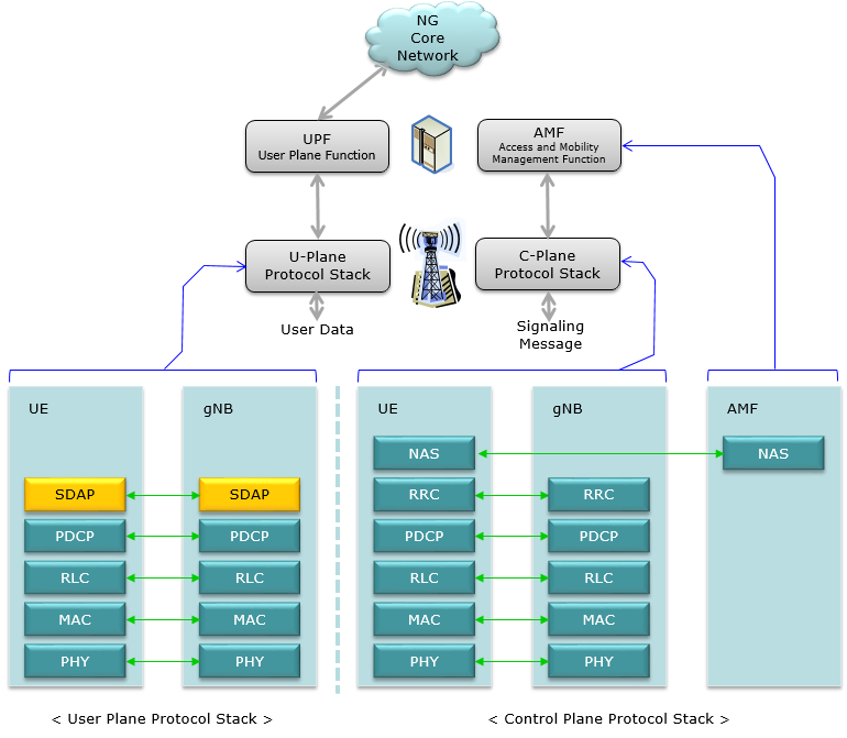
As in LTE / WCDMA, NR radio protocol stack has two different stack depending on the type of data that is processed by the stack. If the data is Signaling message, it goes through the C-plane stack and if it is user data, it goes through U-Plane stack. Both U-Plane and C-Plane is made up of a common structure : PHY <-> MAC <-> RLC <-> PDCP, but the components sitting on top of PHY/MAC/RLC/PDCP gets different between C-Plane and U-Plane. In case of U-Plane, a layer called SDAP is sitting at the top of the radio stack and the SDP is connected to UPF (User Plane Function). In case of C-Plane, the two layers RRC and NAS are sitting at the top of the stack. NAS layer gets connected to AMF (Access and Mobility Management Function).
What I've mentioned can be described in a block diagram as shown below.
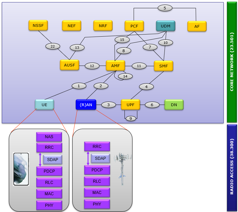
Exploding the architecture into more detailed level, it can be illustrated as follows. The entire system is made up of roughly two part : Radio Accesss component and Core Network component. The main component of Radio Access parts are UE (e.g, mobile phone) and RAN (e.g, gNB, eNB etc) and the core network components are the remaining parts outside of UE and RAN.
Message Flow across the System
This is to show overall signal flow through the entire system with focus on radio access network. This image illustrates the high-level process of message flow in a 5G network, starting from the user's mobile device and moving through various network components until it reaches the data server. The arrows indicate the direction of the data flow, illustrating a complete cycle of communication from the user's device to the network and back.
Click on the image or here and you can get the animated slideshow for this flow and descriptions of each steps.
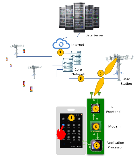
High level description of the signal flow depicted on this illustration is :
-
The user interacts with an application on their smartphone, which generates data to be transmitted.
-
The smartphone's modem and application processor work together to prepare and encode this data for transmission.
-
The data is then transmitted as a radio signal via the device's RF (Radio Frequency) frontend.
-
This radio signal is received by a base station (part of the 5G Radio Access Network).
-
The base station forwards the data to the core network, which is responsible for overall network management and internet connectivity.
-
The core network connects to the broader internet, routing the data to the appropriate data server.
-
The data server receives the request, processes it, and generates a response.
-
The response follows the reverse path: from the data server back to the internet, through the core network and base station, and finally to the user's smartphone, where it's processed by the modem and application processor for the user to view or use
System Component and Specification Mapping
If you are working in cellular communication industry or studying seriously in this area, you know you have to live with a huge set of specification documents called 3GPP TS(Test Specification). However you would often have difficulties in finding the appropriate documents for a specific topics you want to look into.
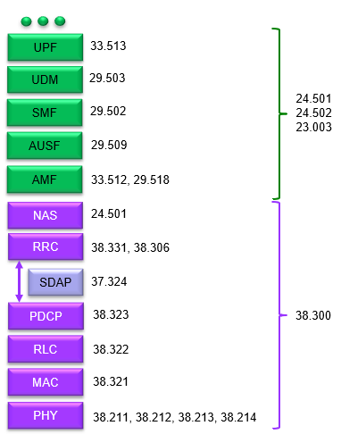
I want to give you some high level mapping to each of the area of 5G system as summarized below. I think this would cover the fundamental parts of each components, but this is not the entire list. You may look into many of additional documents especially for core network components, but the specification listed here can definitely be a good starting point.
This table outlines system components and their corresponding 3GPP specification numbers for 5G networks. I want you to use this table as a cheatsheet to map each network function with its technical specification, which is essential for developers, engineers, and researchers working with 5G technology to ensure compliance with international standards. The notes and references indicated by numbers in brackets ([1], [2], [3], etc.) are likely to provide additional context or details relevant to each component or specification. If you click on the numbers, it will take you to the note on sharetechnote with the detailed technical information.
|
Notes on Sharetechnote |
System Architecture |
|
|
 |
|
|
|
|
|
|
Followings are the text version of this table with direct link to 3GPP document site
- System Level Specification for Core Network : TS 24.501, 24.502, 23.003
- UPF (User Plane Function): Specified by 3GPP TS 33.513.
- UDM (Unified Data Management): Specified by 3GPP TS 29.503.
- SMF (Session Management Function): Specified by 3GPP TS 29.502.
- AUSF (Authentication Server Function): Specified by 3GPP TS 29.509.
- AMF (Access and Mobility Management Function): Specified by 3GPP TS 33.512 and TS 29.518.
- System Level Specification for Access Network : TS 38.300
- NAS (Non-Access Stratum): Specified by 3GPP TS 24.501.
- RRC (Radio Resource Control): Specified by 3GPP TS 38.331 and TS 38.306.
- SDAP (Service Data Adaptation Protocol): Specified by 3GPP TS 37.324.
- PDCP (Packet Data Convergence Protocol): Specified by 3GPP TS 38.323.
- RLC (Radio Link Control): Specified by 3GPP TS 38.322.
- MAC (Medium Access Control): Specified by 3GPP TS 38.321.
- PHY (Physical Layer): Specified by multiple documents including 3GPP TS 38.211, 38.212, 38.213, and 38.214.
L2 Radio Stack Overview
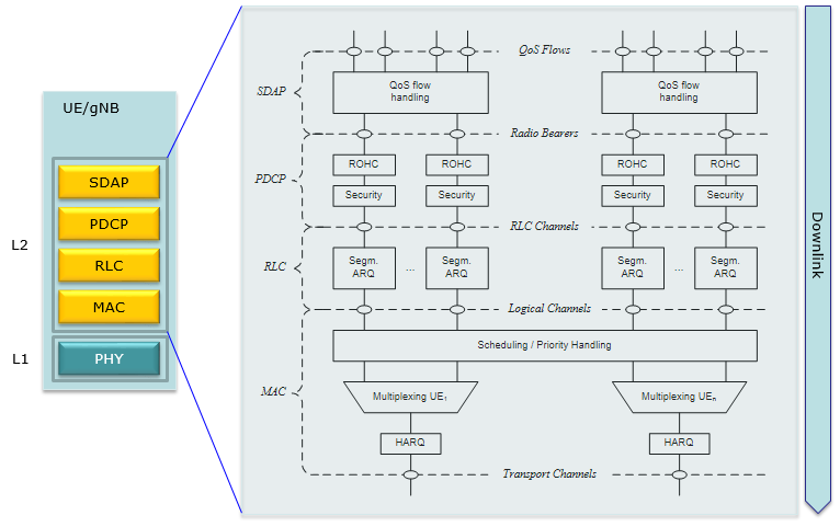
Now let's look just one step further into the protocol stack. Take a look at the L2 (layer 2) structure of the NR U-Plane radio protocol. The structure of L2 downlink stack can be illustrated as shown below. Except the new layer called SDAP, you would notice that the overall structure is almost identical to LTE L2 structure. NR support carrier aggregation from the beginning, data for each carrier is processed separately for each carrier in SDAP, PDCP, RLC and multiplexed/scheduled in the common MAC layer. This is also same as LTE Rel 10 or higher.
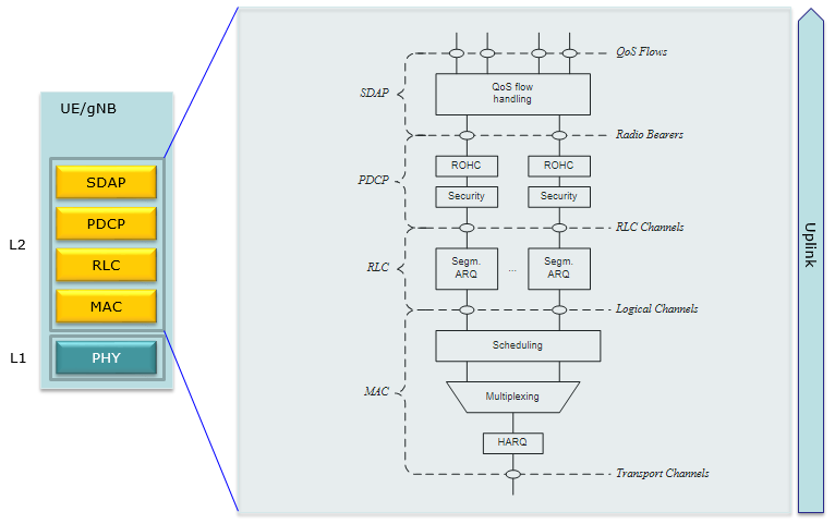
Following is L2 structure of NR U-Plane Uplink radio protocol. Basic structure is same as downlink structure except that Uplink does not support carrier aggregation.
PHY Layer Topics
Regardless of the generations from 2G through 5G, there are some common features/functionalities even though the detailed mechanism and implementation are different. There are alsom some features/functionalities that are specific to a specific radio technology.
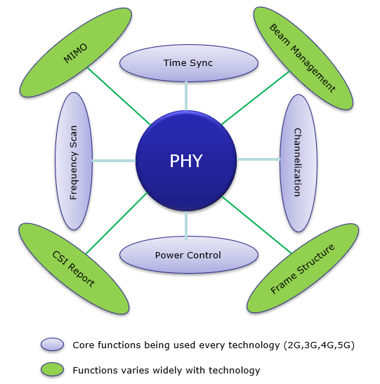
Each of these items are a huge topics and there are even more items not mentioned here. A very brief description of these items are :
Frequency Scan : Scanning different frequencies to identify the best ones for use in communication.Time Synchronization : Ensuring that the transmission and reception of signals are precisely timed across the network.Channelization : The process of definining multiple different physical resource properties and transmitting the data (e.g, user traffic, control data, sync signal etc) via different profile called 'channel'.Power Control : Managing the power levels used for signal transmission to optimize performance and reduce interference.Beam Management : In the context of 5G, this would involve the management of beamforming processes for directional signal transmission and reception.Frame Structure : Defining the format of data frames for efficient communication and data delivery.CSI Report : Channel State Information reporting, which involves the mobile device reporting back to the network on the quality of the received signal.MIMO : Stands for Multiple Input Multiple Output, a method for multiplying the capacity of a radio link using multiple transmission and receiving antennas to exploit multipath propagation.
Reference
[1]